Interfacing the Serial/RS-232 Port
Interfacing the Serial/RS-232 Port
Interfacing the Serial/RS-232 Port

Create successful ePaper yourself
Turn your PDF publications into a flip-book with our unique Google optimized e-Paper software.
<strong>Interfacing</strong> <strong>the</strong> <strong>Serial</strong> / <strong>RS</strong><strong>232</strong> <strong>Port</strong> V5.0<br />
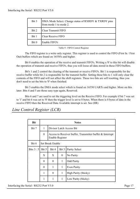
Bit 3<br />
Bit 2<br />
Bit 1<br />
Bit 0<br />
DMA Mode Select. Change status of RXRDY & TXRDY pins<br />
from mode 1 to mode 2.<br />
Clear Transmit FIFO<br />
Clear Receive FIFO<br />
Enable FIFO's<br />
Table 9 : FIFO Control Register<br />
The FIFO register is a write only register. This register is used to control <strong>the</strong> FIFO (First In / First<br />
Out) buffers which are found on 16550's and higher.<br />
Bit 0 enables <strong>the</strong> operation of <strong>the</strong> receive and transmit FIFO's. Writing a '0' to this bit will disable<br />
<strong>the</strong> operation of transmit and receive FIFO's, thus you will loose all data stored in <strong>the</strong>se FIFO buffers.<br />
Bit's 1 and 2 control <strong>the</strong> clearing of <strong>the</strong> transmit or receive FIFO's. Bit 1 is responsible for <strong>the</strong><br />
receive buffer while bit 2 is responsible for <strong>the</strong> transmit buffer. Setting <strong>the</strong>se bits to 1 will only clear <strong>the</strong><br />
contents of <strong>the</strong> FIFO and will not affect <strong>the</strong> shift registers. These two bits are self resetting, thus you<br />
don't need to set <strong>the</strong> bits to '0' when finished.<br />
Bit 3 enables <strong>the</strong> DMA mode select which is found on 16550 UARTs and higher. More on this<br />
later. Bits 4 and 5 are those easy type again, Reserved.<br />
Bits 6 and 7 are used to set <strong>the</strong> triggering level on <strong>the</strong> Receive FIFO. For example if bit 7 was set<br />
to '1' and bit 6 was set to '0' <strong>the</strong>n <strong>the</strong> trigger level is set to 8 bytes. When <strong>the</strong>re is 8 bytes of data in <strong>the</strong><br />
receive FIFO <strong>the</strong>n <strong>the</strong> Received Data Available interrupt is set. See (IIR)<br />
Line Control Register (LCR)<br />
Bit<br />
Notes<br />
Bit 7 1 Divisor Latch Access Bit<br />
0 Access to Receiver buffer, Transmitter buffer & Interrupt<br />
Enable Register<br />
Bit 6<br />
Set Break Enable<br />
Bits 3 : 5 Bit 5 Bit 4 Bit 3 Parity Select<br />
X X 0 No Parity<br />
0 0 1 Odd Parity<br />
0 1 1 Even Parity<br />
1 0 1 High Parity (Sticky)<br />
1 1 1 Low Parity (Sticky)<br />
<strong>Interfacing</strong> <strong>the</strong> <strong>Serial</strong> / <strong>RS</strong><strong>232</strong> <strong>Port</strong> V5.0 Page 17