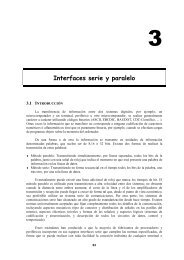
Interfacing the Serial/RS-232 Port
Interfacing the Serial/RS-232 Port
Interfacing the Serial/RS-232 Port

Create successful ePaper yourself
Turn your PDF publications into a flip-book with our unique Google optimized e-Paper software.
<strong>Interfacing</strong> <strong>the</strong> <strong>Serial</strong> / <strong>RS</strong><strong>232</strong> <strong>Port</strong> V5.0<br />
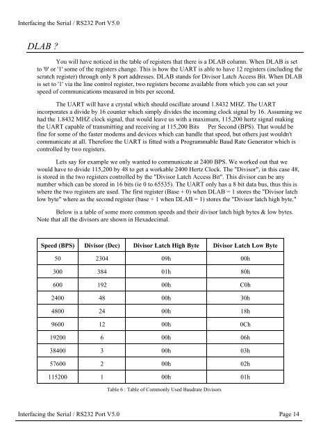
DLAB <br />
You will have noticed in <strong>the</strong> table of registers that <strong>the</strong>re is a DLAB column. When DLAB is set<br />
to '0' or '1' some of <strong>the</strong> registers change. This is how <strong>the</strong> UART is able to have 12 registers (including <strong>the</strong><br />
scratch register) through only 8 port addresses. DLAB stands for Divisor Latch Access Bit. When DLAB<br />
is set to '1' via <strong>the</strong> line control register, two registers become available from which you can set your<br />
speed of communications measured in bits per second.<br />
The UART will have a crystal which should oscillate around 1.8432 MHZ. The UART<br />
incorporates a divide by 16 counter which simply divides <strong>the</strong> incoming clock signal by 16. Assuming we<br />
had <strong>the</strong> 1.8432 MHZ clock signal, that would leave us with a maximum, 115,200 hertz signal making<br />
<strong>the</strong> UART capable of transmitting and receiving at 115,200 Bits Per Second (BPS). That would be<br />
fine for some of <strong>the</strong> faster modems and devices which can handle that speed, but o<strong>the</strong>rs just wouldn't<br />
communicate at all. Therefore <strong>the</strong> UART is fitted with a Programmable Baud Rate Generator which is<br />
controlled by two registers.<br />
Lets say for example we only wanted to communicate at 2400 BPS. We worked out that we<br />
would have to divide 115,200 by 48 to get a workable 2400 Hertz Clock. The "Divisor", in this case 48,<br />
is stored in <strong>the</strong> two registers controlled by <strong>the</strong> "Divisor Latch Access Bit". This divisor can be any<br />
number which can be stored in 16 bits (ie 0 to 65535). The UART only has a 8 bit data bus, thus this is<br />
where <strong>the</strong> two registers are used. The first register (Base + 0) when DLAB = 1 stores <strong>the</strong> "Divisor latch<br />
low byte" where as <strong>the</strong> second register (base + 1 when DLAB = 1) stores <strong>the</strong> "Divisor latch high byte."<br />
Below is a table of some more common speeds and <strong>the</strong>ir divisor latch high bytes & low bytes.<br />
Note that all <strong>the</strong> divisors are shown in Hexadecimal.<br />
Speed (BPS) Divisor (Dec) Divisor Latch High Byte Divisor Latch Low Byte<br />
50 2304 09h 00h<br />
300 384 01h 80h<br />
600 192 00h C0h<br />
2400 48 00h 30h<br />
4800 24 00h 18h<br />
9600 12 00h 0Ch<br />
19200 6 00h 06h<br />
38400 3 00h 03h<br />
57600 2 00h 02h<br />
115200 1 00h 01h<br />
Table 6 : Table of Commonly Used Baudrate Divisors<br />
<strong>Interfacing</strong> <strong>the</strong> <strong>Serial</strong> / <strong>RS</strong><strong>232</strong> <strong>Port</strong> V5.0 Page 14