Interfacing the Serial/RS-232 Port
Interfacing the Serial/RS-232 Port
Interfacing the Serial/RS-232 Port

You also want an ePaper? Increase the reach of your titles
YUMPU automatically turns print PDFs into web optimized ePapers that Google loves.
<strong>Interfacing</strong> <strong>the</strong> <strong>Serial</strong> / <strong>RS</strong><strong>232</strong> <strong>Port</strong> V5.0<br />
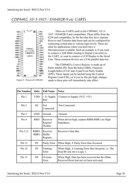
CDP6402, AY-5-1015 / D36402R-9 etc UARTs<br />
There are UARTs such as <strong>the</strong> CDP6402, AY-5-<br />
1015 / D36402R-9 and compatibles. These differ from <strong>the</strong><br />
8250 and compatibles, by <strong>the</strong> fact that <strong>the</strong>y have separate<br />
Receive and Transmit data buses and can be configured by<br />
connecting certain pins to various logic levels. These are<br />
ideal for applications where you don't have a<br />
Microprocessor available. Such an example is if you want<br />
to connect a ADC0804 (Analog to Digital Converter) to<br />
<strong>the</strong> UART, or want to connect a LCD Display to <strong>the</strong> <strong>Serial</strong><br />
Line. These common devices use a 8 bit parallel data bus.<br />
Figure 9 : Pinout of CDP6402<br />
The CDP6402's Control Register is made up of<br />
Parity Inhibit (PI), Stop Bit Select (SBS), Character<br />
Length Select (CLS1 and 2) and Even Parity Enable<br />
(EPE). These inputs can be latched using <strong>the</strong> Control<br />
Register Load (CRL) or if you tie this pin high, changes<br />
made to <strong>the</strong>se pins will immediately take effect.<br />
Pin Number Abbr. Full Name Notes<br />
Pin 1 VDD + 5v Supply<br />
Rail<br />
Pin 2 NC Not<br />
Connected<br />
Connect to Supply (VCC +5V)<br />
Not Connected.<br />
Pin 3 GND Ground Ground.<br />
Pin 4 RRD Receiver<br />
Register<br />
Disable<br />
When driven high, outputs RBR8:RBR1 are High<br />
Impedance.<br />
Pin 5:12<br />
RBR8:<br />
RBR1<br />
Receiver<br />
Buffer<br />
Register<br />
Receiver's Data Bus<br />
Pin 13 PE Parity Error When High, A Parity Error Has Occurred.<br />
Pin 14 FE Framing<br />
Error<br />
Pin 15 OE Overrun<br />
Error<br />
When High, A Framing Error Has Occurred. i.e. The<br />
Stop Bit was not a Logic 1.<br />
When High, Data has been received but <strong>the</strong> nData<br />
Received Reset had not yet been activated.<br />
<strong>Interfacing</strong> <strong>the</strong> <strong>Serial</strong> / <strong>RS</strong><strong>232</strong> <strong>Port</strong> V5.0 Page 36