Download - Harting
Download - Harting
Download - Harting

Create successful ePaper yourself
Turn your PDF publications into a flip-book with our unique Google optimized e-Paper software.
tec.News 17: HARTING Technology Group<br />
Information provided by injection mold simulation<br />
Process-related Product-related Cost factors<br />
Fillability Porosity Machine size<br />
Pressure effects Shrinkage and warpage Cycle time<br />
Temperature distribution Location of weld seams Reduction in rework<br />
Effectiveness of cooling Quality of weld seams Lower material consumption<br />
Gate balancing<br />
Clamping force<br />
Fiber orientation<br />
Sink marks<br />
The goals and capabilities of simulation<br />
The goal of simulation is to produce a meaningful, highquality<br />
analysis of injection-molded parts as early as<br />
possible in the design cycle. The capabilities range from<br />
simple analysis of the filling process to simulation of the<br />
entire injection molding process, including the gating<br />
system and the mold that will be used later on. Key<br />
parameters such as balanced melt flow, homogeneous<br />
temperature and pressure distribution and the position of<br />
critical weld seams are analyzed up front and optimized<br />
on the virtual product. Besides optimizing part geometry,<br />
engineers can simulate the injection mold process. They<br />
can vary and analyze characteristic process parameters<br />
such as the temperature of the tool and the melt, injection<br />
speed and pressure, the holding pressure profile and<br />
cooling time. Shorter correction loops and reduced cycle<br />
times save time and money later on.<br />
Case study<br />
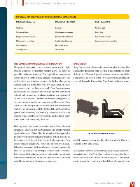
Snap fit joints are often used to assemble plastic parts. The<br />
application discussed here (see fig. 1) is a detachable snap<br />
fit joint on a T-feeder. Figure 2 shows a cross-section of the<br />
cantilever. The results of the fiber distribution simulation<br />
are visible on the illustration. The fibers in the red zones<br />
Linking injection mold simulation with finite element<br />
structural analysis for thermoplastics is another major<br />
application area. Glass fiber is added to thermoplastics<br />
to improve the mechanical properties. When the plastic<br />
is melted and injected into the tool, the complex flow<br />
characteristics create local variations in fiber orientation.<br />
When the parts cool, their mechanical properties generally<br />
tend to be heavily anisotropic rather than isotropic.<br />
Injection mold simulation provides information about local<br />
glass fiber distribution, which can then be used as an input<br />
variable for subsequent structural analysis.<br />
Fig.1: T-Infeeder with snap-fit joints<br />
exhibit strong orientation. Distribution of the fibers is<br />
random in the blue zones.<br />
Elastic finite element structural analysis using an isotropic<br />
material model and 35% fiber content produces the forcetravel<br />
curve that is shown in red in figure 3. The black<br />
curve shows the result when local fiber alignment from<br />
52 harting tec.News 17 (2009)