Download - Harting
Download - Harting
Download - Harting

Create successful ePaper yourself
Turn your PDF publications into a flip-book with our unique Google optimized e-Paper software.
without compromising the overall safety,<br />
reliability and flexibility of the system.<br />
The Czech company TENAX CZ s.r.o. worked<br />
closely with HARTING to develop a highperformance<br />
system which offers a complete<br />
range of functions and can be adapted to<br />
the needs of the particular application. A<br />
safe, simple user interface was also a major<br />
design goal.<br />
A functional block design that can be tailored<br />
to individual customer needs was chosen<br />
to meet these requirements. The company<br />
can provide systems with automatic control,<br />
semi-automatic control or full manual<br />
control. Modularity is a key feature of the<br />
mechanical design as well. All of the mechanical parts<br />
are prefabricated, and they can be assembled to make a<br />
building-block kit which is easy to erect and take down<br />
again. All of the elements are designed to withstand harsh<br />
climatic conditions and high mechanical stress (IP 65, antivandalism).<br />
At the push of a button<br />
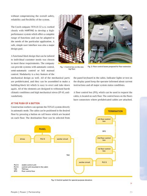
Construction workers can operate the TENAX system directly<br />
in automatic mode. The cabin can be positioned to the desired<br />
floor by pressing a button on call boxes which are located<br />
on each floor. The destination floor can be selected from<br />
Fig. 1: Control box on the new<br />
top floor<br />
Fig. 2: Floor control boxes prepared for floor extension<br />
the panel keyboard in the cabin. Indicator lights or text on<br />
the display panel keep the operator informed about current<br />
instructions and all major system status conditions.<br />
A floor control box (PO), which can be used to request the<br />
cabin, is located on each floor. The control boxes on the floors<br />
have connectors where prefabricated cables are attached.<br />
nth floor control<br />
box<br />
termination<br />
panel<br />
SPO<br />
drives PLC K exciter circuit<br />
2nd floor control<br />
box<br />
1st floor control<br />
box<br />
TNX<br />
PLC S<br />
PLC K<br />
TNX<br />
SPO<br />
stable control unit<br />
control unit mounted in the cabin<br />
TNX bus<br />
floor control bus<br />
exciter circuit<br />
PLC S<br />
Fig. 3: Control system for special-purpose elevators<br />
3<br />
73