Download - Harting
Download - Harting
Download - Harting

You also want an ePaper? Increase the reach of your titles
YUMPU automatically turns print PDFs into web optimized ePapers that Google loves.
tec.News 17: Kaleidoscope<br />
sub-bus structures, signal functions, timing devices, signal<br />
voltages and master/slave configurations are predetermined.<br />
The default requirements of the VME standard VME64<br />
include a 64-bit data path for boards with 6 rack units<br />
(RU), one 32-bit data path for boards with 3 RU, twice the<br />
bandwidth for data transmission, low noise levels and plugand-play<br />
functions. An upgraded version of this standard<br />
called VME64x also supports hot-swapping. VME64 boards<br />
are compatible with older VME bus systems, so they can also<br />
be used in older VME bus systems and vice versa. VME64<br />
is an expanded version for 64-bit data transmission and<br />
addressing.<br />
A typical transmission consists of an arbitration cycle<br />
(for preservation of the bus control), an address cycle<br />
(for selection of the register) and the actual data cycle.<br />
The process supports read, write, modification and block<br />
transmissions.<br />
(ANSI/VITA 1-1994) interface. These modules are connected<br />
in parallel via a plug connector to the carrier module<br />
(mezzanine modules). All of these I/O modules have a shared<br />
carrier to which various modules are connected in parallel.<br />
The mechanical specification of the carrier module is based<br />
on a VMEbus module with 6 rack units according to ANSI/<br />
VITA specification 1-1994. It is also equipped with two<br />
standard P3 and P4 DIN 41 612 connectors compliant with<br />
VME64 on the front for the I/O field interface. According<br />
to the electrical specifications of VME64, the module<br />
represents a sub-system (a so-called slave) with A16/D16/<br />
D08 (EO) interface on the VMEbus. It receives and controls<br />
The VME bus system is made up of 4 sub-buses: the Data<br />
Transmission Bus, the Arbitration Bus, the Priority Interrupt<br />
Bus and the Utility Bus. The asynchronous data transmission<br />
supports modules with many different response times.<br />
Developed as a flexible environment for a large number<br />
of processor-intensive tasks, the VME bus has evolved<br />
into a widely used protocol in the computer industry. Its<br />
development is based on the IEEE 1014-1987 standard.<br />
HARTING is the connector and backplane<br />
supplier<br />
HARTING India was involved with Omnie right from the<br />
start of the project and later selected as the chosen supplier<br />
of DIN 41 612 connectors, metric cPCI connectors, SEK<br />
Interface connectors and D Sub connectors for high-speed<br />
I/O boards. Subsequently during the project, Omnie also<br />
took the decision to procure the backplanes from HARTING<br />
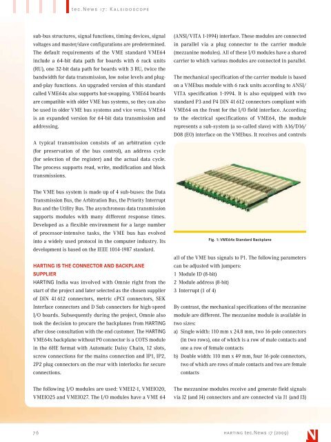
after close consultation with the end customer. The HARTING<br />
VME64x backplane without P0 connector is a COTS module<br />
in the 6HE format with Automatic Daisy Chain, 12 slots,<br />
screw connections for the mains connection and IP1, IP2,<br />
2P2 plug connectors on the rear with interlocks for secure<br />
connections.<br />
Fig. 1: VME64x Standard Backplane<br />
all of the VME bus signals to P1. The following parameters<br />
can be adjusted with jumpers:<br />
1 Module ID (8-bit)<br />
2 Module address (8-bit)<br />
3 Interrupt (1 of 4)<br />
By contrast, the mechanical specifications of the mezzanine<br />
module are different. The mezzanine module is available in<br />
two sizes:<br />
a) Single width: 110 mm x 24.8 mm, two 16-pole connectors<br />
(in two rows), one of which is a row of male contacts and<br />
one a row of female contacts<br />
b) Double width: 110 mm x 49 mm, four 16-pole connectors,<br />
two of which are rows of male contacts and two are female<br />
contacts<br />
The following I/O modules are used: VMEI2-1, VMEIO20,<br />
VMEIO25 and VMEIO27. The I/O modules have a VME 64<br />
The mezzanine modules receive and generate field signals<br />
via J2 (and J4) connectors and are connected via J1 (and J3)<br />
76 harting tec.News 17 (2009)