Download - Harting
Download - Harting
Download - Harting

You also want an ePaper? Increase the reach of your titles
YUMPU automatically turns print PDFs into web optimized ePapers that Google loves.
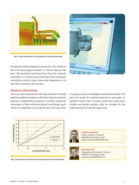
Fig. 2: Fiber orientation in the cantilever (cross-sectional view)<br />
the injection mold simulation is factored in. The cantilever<br />
has to be moved approximately 1.5 mm to separate the<br />
joint. The predicted activation force from the isotropic<br />
calculation is 1.5 times greater than that of the anisotropic<br />
calculation, and this clearly shows how important it is to<br />
take fiber orientation into account.<br />
Potential applications<br />
This case study demonstrates the huge potential of linking<br />
injection molding simulation with finite element structural<br />
analysis. Computational engineers can fully exploit the<br />
advantages of fiber-reinforced plastics and design parts<br />
which are compatible with the plastic they are using. Work<br />
is ongoing on these technologies and material models. The<br />
goal is to model the material behavior as accurately as<br />
possible, reduce time to market, make the results more<br />
reliable and design products that are suitable for the<br />
production process and the application.<br />
ACTIVATION FORCE [N]<br />
anisotropic<br />
isotropic<br />
Thomas Heimann<br />
Project Engineer, Germany<br />
HARTING Technology Group<br />
thomas.heimann@HARTING.com<br />
ACTIVATION way [mm]<br />
Fig. 3: Comparison of isotropic and anisotropic FE structural analysis<br />
Matthias Keil<br />
Computational Engineer, Germany<br />
HARTING Technology Group<br />
matthias.keil@HARTING.com<br />
53