PROFIBUS-DP OPTION OPC-G11S-PDP for ... - Fuji Electric America
PROFIBUS-DP OPTION OPC-G11S-PDP for ... - Fuji Electric America
PROFIBUS-DP OPTION OPC-G11S-PDP for ... - Fuji Electric America

Create successful ePaper yourself
Turn your PDF publications into a flip-book with our unique Google optimized e-Paper software.
8. Parameters specific <strong>for</strong> communication<br />
USER MANUAL<br />
Revision 0.14<br />
2000-01-14<br />
To operate the inverters or to monitor the state via communication, the following parameters are available <strong>for</strong><br />
communication in addition to the configuration functions of the inverters. These parameters are a common data <strong>for</strong>mat<br />
applicable to inverter types on and after G11/P11 series, so that it is possible to access different inverter types by the<br />
same program on the host side.<br />
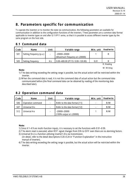
8.1 Command data<br />
Code Name Unit Variable range Min. unit Read/write<br />
S01 Setting frequency (p.u.) - -20000–20000<br />
(Maximum frequency at ±20000)<br />
1 R<br />
S05 Setting frequency Hz 0.00–400.00 (P11S: 0.00–120.00) 0.01 R<br />
R: Reading<br />
W: Writing<br />
Note:<br />
1) The data writing exceeding the setting range is possible, but the actual action will be restricted within the<br />
inverter.<br />
2) When the command data is read, it is not the command data of actual action but the command data<br />
communicated be<strong>for</strong>e (the final command data can be obtained by reading of the monitoring data<br />
described later).<br />
8.2 Operation command data<br />
Code Name Unit Variable range Min. unit Read/write<br />
S06 Operation command - Refer to the data <strong>for</strong>mat [11] - R/W<br />
S07 Universal Do - Refer to the data <strong>for</strong>mat [12] - R/W<br />
S12 Universal Ao - -20000–20000<br />
(100% output at ±20000)<br />
1 R/W<br />
Note:<br />
1) Since X1–X9 are multi-function inputs, it is necessary to set the functions with E01–E09.<br />
2) The alarm reset is executed, when RST signal changes from ON to OFF even there are no alarming factors.<br />
3) Universal Do is a function utilizing inverter’s Do via transmission.<br />
(In detail, refer to the detail descriptions E20–E24 in "Function Explanation" in the instruction<br />
manual of inverter).<br />
4) The data writing exceeding the setting range is possible, but the actual action will be restricted within the<br />
inverter.<br />
HMS FIELDBUS SYSTEMS AB 38