Svetsaren_nr2 definitief (Page 1) - Esab
Svetsaren_nr2 definitief (Page 1) - Esab
Svetsaren_nr2 definitief (Page 1) - Esab

Create successful ePaper yourself
Turn your PDF publications into a flip-book with our unique Google optimized e-Paper software.
November 1997, thereby completing the first major<br />
construction stage. Phase 2 began in 1998 and is due to<br />
end in 2003, when the water level will rise to 156m and<br />
the dam will start generating electricity. There are plans<br />
to open a permanent ship lock for navigation in the<br />
same year. The ship lock will consist of five locks, each<br />
280m long and 35m wide, with a water depth of 5m,<br />
capable of handling 10,000-tonne barges. In addition, a<br />
one-stage vertical ship lift capable of carrying 3,000<br />
tonne passenger or cargo vessel will be built. River<br />
shipping through central Yangtze is expected to increase<br />
from 10 million to 50 million tonnes annually, with a<br />
reduction in transportation costs of 30-37 percent.<br />
Phase 3 is scheduled for completion in 2009, when full<br />
power generation will begin. By then, 102.6 million cubic<br />
metres of earth and stone will have been excavated and<br />
27.2 million cubic metres of concrete and 354,000 tonnes<br />
of steel reinforcing bars will have been used. In the<br />
centre of the dam, there will be a 484-metre spillway<br />
section with 23 bottom outlets and 22 sluice gates. On<br />
the left and right hand sides of the spillway, there will be<br />
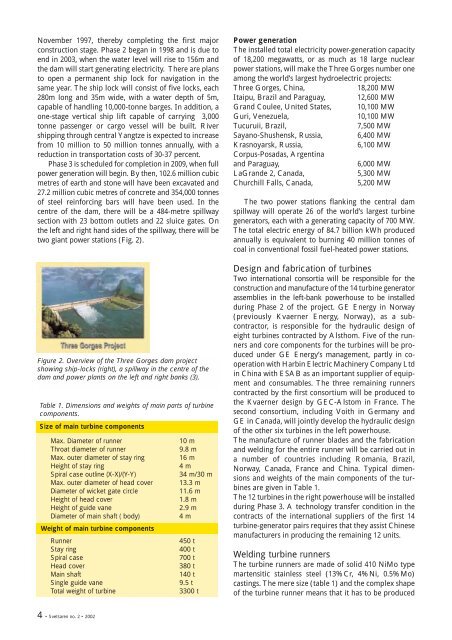
two giant power stations (Fig. 2).<br />
Figure 2. Overview of the Three Gorges dam project<br />
showing ship-locks (right), a spillway in the centre of the<br />
dam and power plants on the left and right banks (3).<br />
Table 1. Dimensions and weights of main parts of turbine<br />
components.<br />
Size of main turbine components<br />
Max. Diameter of runner<br />
Throat diameter of runner<br />
Max. outer diameter of stay ring<br />
Height of stay ring<br />
Spiral case outline (X-X)/(Y-Y)<br />
Max. outer diameter of head cover<br />
Diameter of wicket gate circle<br />
Height of head cover<br />
Height of guide vane<br />
Diameter of main shaft ( body)<br />
Weight of main turbine components<br />
Runner<br />
Stay ring<br />
Spiral case<br />
Head cover<br />
Main shaft<br />
Single guide vane<br />
Total weight of turbine<br />
10 m<br />
9.8 m<br />
16 m<br />
4 m<br />
34 m/30 m<br />
13.3 m<br />
11.6 m<br />
1.8 m<br />
2.9 m<br />
4 m<br />
450 t<br />
400 t<br />
700 t<br />
380 t<br />
140 t<br />
9.5 t<br />
3300 t<br />
Power generation<br />
The installed total electricity power-generation capacity<br />
of 18,200 megawatts, or as much as 18 large nuclear<br />
power stations, will make the Three Gorges number one<br />
among the world’s largest hydroelectric projects:<br />
Three Gorges, China,<br />
18,200 MW<br />
Itaipu, Brazil and Paraguay, 12,600 MW<br />
Grand Coulee, United States, 10,100 MW<br />
Guri, Venezuela,<br />
10,100 MW<br />
Tucuruii, Brazil,<br />
7,500 MW<br />
Sayano-Shushensk, Russia, 6,400 MW<br />
Krasnoyarsk, Russia,<br />
6,100 MW<br />
Corpus-Posadas, Argentina<br />
and Paraguay,<br />
6,000 MW<br />
LaGrande 2, Canada,<br />
5,300 MW<br />
Churchill Falls, Canada,<br />
5,200 MW<br />
The two power stations flanking the central dam<br />
spillway will operate 26 of the world’s largest turbine<br />
generators, each with a generating capacity of 700 MW.<br />
The total electric energy of 84.7 billion kWh produced<br />
annually is equivalent to burning 40 million tonnes of<br />
coal in conventional fossil fuel-heated power stations.<br />
Design and fabrication of turbines<br />
Two international consortia will be responsible for the<br />
construction and manufacture of the 14 turbine generator<br />
assemblies in the left-bank powerhouse to be installed<br />
during Phase 2 of the project. GE Energy in Norway<br />
(previously Kvaerner Energy, Norway), as a subcontractor,<br />
is responsible for the hydraulic design of<br />
eight turbines contracted by Alsthom. Five of the runners<br />
and core components for the turbines will be produced<br />
under GE Energy’s management, partly in cooperation<br />
with Harbin Electric Machinery Company Ltd<br />
in China with ESAB as an important supplier of equipment<br />
and consumables. The three remaining runners<br />
contracted by the first consortium will be produced to<br />
the Kvaerner design by GEC-Alstom in France. The<br />
second consortium, including Voith in Germany and<br />
GE in Canada, will jointly develop the hydraulic design<br />
of the other six turbines in the left powerhouse.<br />
The manufacture of runner blades and the fabrication<br />
and welding for the entire runner will be carried out in<br />
a number of countries including Romania, Brazil,<br />
Norway, Canada, France and China. Typical dimensions<br />
and weights of the main components of the turbines<br />
are given in Table 1.<br />
The 12 turbines in the right powerhouse will be installed<br />
during Phase 3. A technology transfer condition in the<br />
contracts of the international suppliers of the first 14<br />
turbine-generator pairs requires that they assist Chinese<br />
manufacturers in producing the remaining 12 units.<br />
Welding turbine runners<br />
The turbine runners are made of solid 410 NiMo type<br />
martensitic stainless steel (13%Cr, 4%Ni, 0.5%Mo)<br />
castings. The mere size (table 1) and the complex shape<br />
of the turbine runner means that it has to be produced<br />
4 • <strong>Svetsaren</strong> no. 2 • 2002