Svetsaren_nr2 definitief (Page 1) - Esab
Svetsaren_nr2 definitief (Page 1) - Esab
Svetsaren_nr2 definitief (Page 1) - Esab

You also want an ePaper? Increase the reach of your titles
YUMPU automatically turns print PDFs into web optimized ePapers that Google loves.
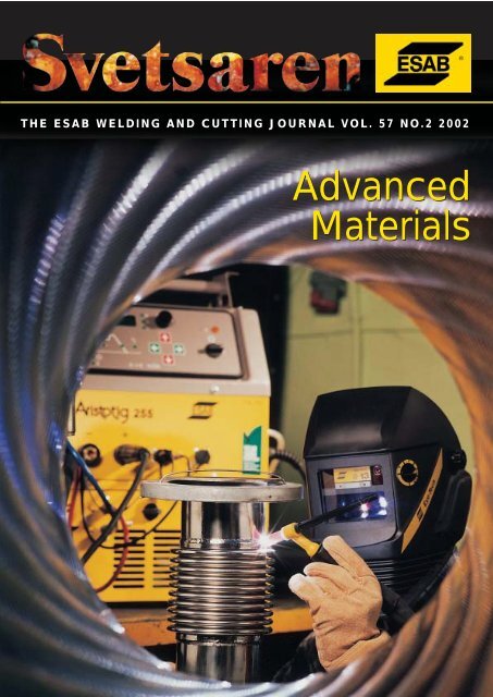
THE ESAB WELDING AND CUTTING JOURNAL VOL. 57 NO.2 2002<br />
Advanced<br />
Materials
THE ESAB WELDING AND CUTTING JOURNAL VOL. 57 NO.2 2002<br />
Articles in <strong>Svetsaren</strong> may be reproduced without permission but with<br />
an acknowledgement to ESAB.<br />
Publisher<br />
Bertil Pekkari<br />
Editor<br />
Ben Altemühl<br />
Editorial committee<br />
Klas Weman, Björn Torstensson, Johnny Sundin, Johan Elvander, Lars-Erik Stridh,<br />
Lars-Göran Eriksson, Uwe Mayer, Manfred Funccius, Dave Meyer, Donna Terry, Tony Anderson<br />
Address<br />
ESAB AB, Box 8004, SE-402 77 Göteborg, Sweden<br />
Internet address<br />
http://www.esab.com<br />
E-mail: info@esab.se<br />
Lay-out: Duco Messie, Printed in the Netherlands<br />
Advanced Materials<br />
Contents Vol. 57 No. 2 2002<br />
3<br />
High deposition welding of Francis turbine<br />
runners for the Three Gorges dam project.<br />
The article informs about the world's largest<br />
hydro power project ever, and describes<br />
ESAB's involvement in the welding of the<br />
Francis turbine runners.<br />
26<br />
Synergic Cold Wire submerged arc welding<br />
Results of research on the application of this<br />
new, cost-efficient welding process to stainless<br />
steel.<br />
9<br />
Welding of copper-nickel alloys at Kvaerner<br />
Masa-Yards.<br />
The orbital TIG welding of copper-nickel<br />
alloy pipes as an alternative to brazing.<br />
32<br />
Welding tramway rails in Bucharest<br />
A report on the use of ESAB's enclosed welding<br />
technique for the joining of tramway rails.<br />
11<br />
Friction Stir Welding- progress in R&D and<br />
new applications<br />
The article presents recent R&D results, a<br />
new machine series, and a fascinating new<br />
application in the welding of thick copper.<br />
36<br />
The mechanised MAG welding of the Clare<br />
natural gas line.<br />
The use of OK 12.65 copper-free wire in the<br />
mechanised GMAW of a new extension of<br />
the Irish national gas grid.<br />
14<br />
Welding of supermartensitic stainless steels.<br />
The orbital narrow gap girth welding of pipes<br />
and the dissimilar joining of supermartensitic<br />
and superduplex pipes.<br />
39<br />
Consumable development for oxidising<br />
chloride containing process environments.<br />
Research work at VTT Technical Research<br />
Centre in Finland.<br />
21<br />
Chicago Bridge & Iron Company meets<br />
challenge of stainless steel welding for<br />
cryogenic rocket fuel tanks<br />
The welding of cryogenic storage tanks for<br />
the Boeing Space Launch Complex 37 at<br />
Cape Canaveral Air Force Station.<br />
45<br />
CIMTAS, an international player in power<br />
generation and energy storage.<br />
The article reviews CIMTAS, a Turkish<br />
fabricator of power plants and other energy<br />
related constructions. The fabrication of two<br />
very large LNG tanks is highlighted.<br />
22<br />
Welding high strength pipelines - from<br />
laboratory to field.<br />
A survey of the developments in the mechanised<br />
GMAW of pipelines in X80 type high<br />
strength steel.<br />
50<br />
Stubends & Spatter<br />
Short news
High deposition welding of<br />
Francis turbine runners for the<br />
Three Gorges dam project<br />
By: Nils Thalberg, Solveig Rigdal, Leif Karlsson, John van den Broek and Herbert Kaufmann, ESAB AB<br />
This paper was originally presented at the Stainless Steel World America 2002 Conference.<br />
The world’s largest hydroelectric project, the Three Gorges dam in China, will<br />
comprise 26 Francis turbines for the production of electricity. Each turbine runner<br />
is 10m in diameter, weighs 450 tonnes and will generate 700 MW. The runners<br />
are made of solid 410 NiMo type martensitic stainless steel (13% Cr, 4% Ni, 0.5%<br />
Mo) castings. Welding is used for the assembly and repair of casting defects.<br />
ESAB is involved in the production of the runners with consumables and<br />
equipment for SAW and GMAW.<br />
Figure 1. Location of Three Gorges Dam.<br />
Three Gorges – the world’s largest<br />
hydroelectric project<br />
In 1994, construction work began on the massive Three<br />
Gorges dam near Yichang (Fig. 1). This dam is expected<br />
to help control the flooding of the Yangtze River valley;<br />
in addition, river flows will make the Three Gorges<br />
complex the largest electricity generating facility in the<br />
world. The negative consequences of the project include<br />
the forced relocation of more than one million people<br />
and the permanent flooding of many historical sites, not<br />
to mention the feared environmental effects.<br />
A lake about 650km long with an average width of<br />
1.1km will form behind the dam, which is 185m high<br />
and about 2,309m wide. The water storage capacity of<br />
the dam will be 39.3 billion cubic metres handling 451<br />
billion cubic metres of Yangtze River water flowing<br />
into the reservoir every year. Dam sponsors say that the<br />
22.1 billion cubic metre flood control storage capacity<br />
of the reservoir should reduce the frequency of large<br />
downstream floods from once every 10 years to once<br />
every 100 years.<br />
The Yangtze River was diverted after four years in<br />
<strong>Svetsaren</strong> no. 2 • 2002 • 3
November 1997, thereby completing the first major<br />
construction stage. Phase 2 began in 1998 and is due to<br />
end in 2003, when the water level will rise to 156m and<br />
the dam will start generating electricity. There are plans<br />
to open a permanent ship lock for navigation in the<br />
same year. The ship lock will consist of five locks, each<br />
280m long and 35m wide, with a water depth of 5m,<br />
capable of handling 10,000-tonne barges. In addition, a<br />
one-stage vertical ship lift capable of carrying 3,000<br />
tonne passenger or cargo vessel will be built. River<br />
shipping through central Yangtze is expected to increase<br />
from 10 million to 50 million tonnes annually, with a<br />
reduction in transportation costs of 30-37 percent.<br />
Phase 3 is scheduled for completion in 2009, when full<br />
power generation will begin. By then, 102.6 million cubic<br />
metres of earth and stone will have been excavated and<br />
27.2 million cubic metres of concrete and 354,000 tonnes<br />
of steel reinforcing bars will have been used. In the<br />
centre of the dam, there will be a 484-metre spillway<br />
section with 23 bottom outlets and 22 sluice gates. On<br />
the left and right hand sides of the spillway, there will be<br />
two giant power stations (Fig. 2).<br />
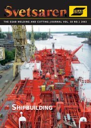
Figure 2. Overview of the Three Gorges dam project<br />
showing ship-locks (right), a spillway in the centre of the<br />
dam and power plants on the left and right banks (3).<br />
Table 1. Dimensions and weights of main parts of turbine<br />
components.<br />
Size of main turbine components<br />
Max. Diameter of runner<br />
Throat diameter of runner<br />
Max. outer diameter of stay ring<br />
Height of stay ring<br />
Spiral case outline (X-X)/(Y-Y)<br />
Max. outer diameter of head cover<br />
Diameter of wicket gate circle<br />
Height of head cover<br />
Height of guide vane<br />
Diameter of main shaft ( body)<br />
Weight of main turbine components<br />
Runner<br />
Stay ring<br />
Spiral case<br />
Head cover<br />
Main shaft<br />
Single guide vane<br />
Total weight of turbine<br />
10 m<br />
9.8 m<br />
16 m<br />
4 m<br />
34 m/30 m<br />
13.3 m<br />
11.6 m<br />
1.8 m<br />
2.9 m<br />
4 m<br />
450 t<br />
400 t<br />
700 t<br />
380 t<br />
140 t<br />
9.5 t<br />
3300 t<br />
Power generation<br />
The installed total electricity power-generation capacity<br />
of 18,200 megawatts, or as much as 18 large nuclear<br />
power stations, will make the Three Gorges number one<br />
among the world’s largest hydroelectric projects:<br />
Three Gorges, China,<br />
18,200 MW<br />
Itaipu, Brazil and Paraguay, 12,600 MW<br />
Grand Coulee, United States, 10,100 MW<br />
Guri, Venezuela,<br />
10,100 MW<br />
Tucuruii, Brazil,<br />
7,500 MW<br />
Sayano-Shushensk, Russia, 6,400 MW<br />
Krasnoyarsk, Russia,<br />
6,100 MW<br />
Corpus-Posadas, Argentina<br />
and Paraguay,<br />
6,000 MW<br />
LaGrande 2, Canada,<br />
5,300 MW<br />
Churchill Falls, Canada,<br />
5,200 MW<br />
The two power stations flanking the central dam<br />
spillway will operate 26 of the world’s largest turbine<br />
generators, each with a generating capacity of 700 MW.<br />
The total electric energy of 84.7 billion kWh produced<br />
annually is equivalent to burning 40 million tonnes of<br />
coal in conventional fossil fuel-heated power stations.<br />
Design and fabrication of turbines<br />
Two international consortia will be responsible for the<br />
construction and manufacture of the 14 turbine generator<br />
assemblies in the left-bank powerhouse to be installed<br />
during Phase 2 of the project. GE Energy in Norway<br />
(previously Kvaerner Energy, Norway), as a subcontractor,<br />
is responsible for the hydraulic design of<br />
eight turbines contracted by Alsthom. Five of the runners<br />
and core components for the turbines will be produced<br />
under GE Energy’s management, partly in cooperation<br />
with Harbin Electric Machinery Company Ltd<br />
in China with ESAB as an important supplier of equipment<br />
and consumables. The three remaining runners<br />
contracted by the first consortium will be produced to<br />
the Kvaerner design by GEC-Alstom in France. The<br />
second consortium, including Voith in Germany and<br />
GE in Canada, will jointly develop the hydraulic design<br />
of the other six turbines in the left powerhouse.<br />
The manufacture of runner blades and the fabrication<br />
and welding for the entire runner will be carried out in<br />
a number of countries including Romania, Brazil,<br />
Norway, Canada, France and China. Typical dimensions<br />
and weights of the main components of the turbines<br />
are given in Table 1.<br />
The 12 turbines in the right powerhouse will be installed<br />
during Phase 3. A technology transfer condition in the<br />
contracts of the international suppliers of the first 14<br />
turbine-generator pairs requires that they assist Chinese<br />
manufacturers in producing the remaining 12 units.<br />
Welding turbine runners<br />
The turbine runners are made of solid 410 NiMo type<br />
martensitic stainless steel (13%Cr, 4%Ni, 0.5%Mo)<br />
castings. The mere size (table 1) and the complex shape<br />
of the turbine runner means that it has to be produced<br />
4 • <strong>Svetsaren</strong> no. 2 • 2002
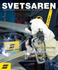
Crown<br />
Vanes<br />
Band<br />
Figure 3. Main components of a Francis turbine runner.<br />
from a number of smaller (yet still impressively sized)<br />
castings. Welding is used to join the separate castings<br />
and repair the casting defects. A combination of<br />
different welding techniques, including manual metal<br />
arc welding (MMA), semi-automatic techniques such<br />
as gas metal arc welding (GMAW) with solid or cored<br />
wires and fully-mechanised welding with submerged<br />
arc welding (SAW), is being used. The specific choice of<br />
method varies depending on factors such as joint<br />
geometry, accessibility and the cost of labour,<br />
equipment and consumables. Different combinations<br />
of welding techniques and consumables will therefore<br />
be used for different turbine runners depending on<br />
location and the responsible company.<br />
The three main components of a Francis turbine<br />
runner are the runner crown, the vanes and the runner<br />
band (fig. 3). In all, approximately 7-10 tonnes of<br />
welding consumables will be used for the assembly of<br />
each runner. Most of this is needed to join the vanes to<br />
the crown and the band. The first sections will focus on<br />
the SAW twin-wire solution chosen by GE Energy for<br />
joining the vanes to the crown. Pre-production tests and<br />
experience of using semi-automatic welding with metalcored<br />
wires will then be discussed.<br />
Fully-mechanised SAW of vanes to runner<br />
crown<br />
GE Energy in Norway (formerly Kvaerner Energy)<br />
secured the contract for building three runners, partly<br />
in co-operation with Harbin Electric Machinery<br />
Company Ltd, which received the contract for two<br />
additional turbines. Welding methods with the highest<br />
possible deposition rates were specified to manufacture<br />
runners of this considerable size in a cost effective<br />
manner. The design criteria set by Kvaerner Energy<br />
AS, Norway, were to achieve a deposition rate of no<br />
less than 16 kg/hour. After evaluating different<br />
possibilities, SAW with two wires (twin-arc) was<br />
considered to be the best method based on productivity<br />
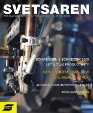
Figure 4. New compact SAW twin arc welding head.<br />
Figure 5. Welding<br />
station with manipulator<br />
and welding head<br />
positioned for welding<br />
turbine runner.<br />
and weld metal quality criteria, as well as previous<br />
experience from other critical applications. However,<br />
the full productivity potential needs to be utilised while<br />
the welding head precisely follows the approximately<br />
4m long joints with complicated three-dimensional<br />
geometry between the turbine runner vanes and the<br />
runner crown/runner band (Fig. 3). The limited access<br />
for the welding head between the vanes is another<br />
complicating factor. A high-accuracy manipulation and<br />
control system is therefore necessary to obtain all the<br />
benefits from a fully-mechanised welding process and<br />
achieve the required productivity.<br />
<strong>Svetsaren</strong> no. 2 • 2002 • 5
Welding equipment<br />
ESAB Welding Equipment AB received a contract from<br />
Kvaerner Energy A/S, Norway, for the design and supply<br />
of two complete, numerically controlled welding manipulators<br />
for welding the Francis turbine runners. To fulfil<br />
the requirements, a new compact welding head had to be<br />
designed (Fig. 4). The mounting permits vertical, horizontal<br />
and rotating movements to allow precise adjustments<br />
as the welding head moves along the joint.<br />
To make it possible to follow the 4m long joint, the welding<br />
head is mounted on a column and boom manipulator,<br />
thereby permitting welding within a working<br />
volume of 2 x 4.3m horizontally and 2m in height (Fig. 5).<br />
The manipulators can be programmed through "teachin",<br />
which means that the welding head is positioned at<br />
various points along the weld preparation and all the<br />
necessary data is stored in the control-box memory.<br />
Individual weld beads can be easily programmed by<br />
simply adding a suitable offset, thereby minimising the<br />
amount of programming required for a multipass weld.<br />
SAW consumables<br />
Approximately three to four tonnes of SAW filler wire<br />
will be used to join the vanes to the crown for each<br />
turbine runner. The welding of root runs and, wherever<br />
necessary, the supplementary welding of filler beads<br />
will mainly be done with GMAW using a metal-cored<br />
wire, as described in a later section.<br />
In addition to the equipment and productivity aspects,<br />
the mechanical and metallurgical properties of the weld<br />
metal and the base material in the as-welded condition,<br />
as well as after PWHT, must comply with stringent<br />
requirements. The specified classification for the wire is<br />
AWS ER 410NiMo, modified as required to fulfil<br />
mechanical and weldability requirements. This consumable<br />
will deposit a weld metal with a composition<br />
similar to that of the 410 NiMo type martensitic stainless<br />
steel (13% Cr, 4% Ni , 0.5% Mo) used in the castings.<br />
The requirements that have to be fulfilled by the<br />
combination of flux and wire include:<br />
• A diffusible hydrogen of less than 3ml per 100g weld<br />
metal.<br />
• A minimum flux basicity index of 2.7.<br />
• Minimum Charpy-V impact toughness of 50 J at 0ºC<br />
after PWHT and a minimum of 20J in the as-welded<br />
condition.<br />
• Accepted bend tests in the as welded condition and<br />
after PWHT.<br />
• Minimum yield strength of 550 MPa and minimum<br />
tensile strength of 760 MPa after PWHT.<br />
• Good weldability, including wetting characteristics,<br />
slag detachability and weld surface appearance for a<br />
maximum welding current of 970A.<br />
After initial tests, the new ESAB wire/flux combination,<br />
OK Autrod 16.79 (2x Ø 2.4mm)/OK Flux 10.63<br />
(Table 2), was shown to deposit a weld metal fulfilling<br />
all the above requirements.<br />
Weld tests<br />
The final acceptance tests for the welding consumables<br />
and welding stations included:<br />
a) welding in 60mm thick material in a symmetrical 45º<br />
X-joint and<br />
b) welding on a specimen simulating a 300mm thick<br />
vane to be welded to a 200mm thick section of the<br />
crown in a symmetrical double J joint.<br />
All the tests were performed on cast material of the<br />
quality to be used in production.<br />
A preheat of 100-150ºC and a maximum interpass<br />
temperature of 200ºC were used with welding<br />
parameters of 970A, typically 31V and welding speeds<br />
of 60-70 cm/min. All the tests were performed with two<br />
Ø 2.4mm wires in line.<br />
Table 2. Welding consumables used for SAW twin wire welding of vanes to runner crown.<br />
Consumable Classification Flux Typical all-weld metal<br />
basicity composition (wt. %)<br />
C Si Mn Cr Ni Mo<br />
OK Flux 10.63 EN 760 SA FB 1 55 AC H5 3.2<br />
OK Autrod 16.79 AWS A 5.9 ER 410 NiMo mod. -<br />
0.02 0.4 0.7 12.3 4.3 0.5<br />
Table 3. Mechanical data from acceptance tests.<br />
Weld Test condition Cross weld Impact Hardness Side bend testing<br />
tensile strength toughness (HV10) (180º, 6xt)<br />
(MPa)<br />
at 0ºC (J)<br />
Weld metal Weld metal<br />
60 mm X-joint As welded 824-829** 34, 31, 33 369-394 no remarks<br />
PWHT* 728-739** 86, 88, 87 284-300 no remarks<br />
300 mm double J-joint PWHT* 838-866** 82, 86, 83 290-305 no remarks<br />
* Post weld heat treatment: 580ºC/ 4 h<br />
** Fracture in base metal<br />
6 • <strong>Svetsaren</strong> no. 2 • 2002
The acceptance criteria included weldability aspects such<br />
as wetting characteristics, slag detachability and weld<br />
surface appearance, mechanical properties (Table 3) and<br />
non-destructive testing using ultrasonic and radiographic<br />
examination. The test results were satisfactory<br />
and ESAB was awarded a contract for the delivery of<br />
two complete welding stations with an option also to<br />
purchase consumables.<br />
Production experience<br />
The thickness of the vane varies along the 4m long joint,<br />
but it is mainly between 70 and 220mm. With a typical<br />
welding current of 700-800A and a welding speed of<br />
70cm/min, some 200-300 weld beads have to be<br />
deposited with heat inputs of about 2kJ/mm for each<br />
joint. Consistent performance and reliability are therefore<br />
just as important as deposition rates during welding.<br />
The welding stations were delivered and assembled in<br />
Huludao in China towards the end of 2000. Non<br />
destructive testing has confirmed the high and<br />
consistent quality of the weld metal and welding is<br />
proceeding as planned without major complications.<br />
GMAW with metal-cored wires<br />
ESAB has a wide range of consumables for hydroturbine<br />
solutions, not only for SAW but also for GMAW<br />
and MMA. In particular, the range of metal-cored wires<br />
(MCW) has a long and successful track record.<br />
Productivity and weldability<br />
Productivity from cored wire welding, regardless of the<br />
wire type used, is always superior to that of manual<br />
welding with manual metal arc stick electrodes, due to<br />
the higher duty cycle. In addition, deposition rates are on<br />
a much higher level. MCWs have little or no slag forming<br />
ingredients in the fill and they also have only a small<br />
amount of arc stabilisers. As with solid wires, welds<br />
display only small islands of de-oxidation products, making<br />
them popular for productive multi-run welding without<br />
inter-run de-slagging. This explains their widespread<br />
use for mechanised and robotic operations. The metalcored<br />
types for turbine applications are medium fillingrate<br />
wires suitable for manual, mechanised and robotic<br />
operation, in all welding positions.<br />
The advantages for turbine fabrication and repair can<br />
be summarised as follows.<br />
• High duty cycle compared with other manual and<br />
semi-automatic welding methods.<br />
• Low spatter operation with well wetted, flat and<br />
fully penetrating beads, leading to significantly<br />
reduced post weld labour.<br />
• Good all-positional weldability, even in the lowcurrent<br />
range.<br />
• Can be welded with conventional or pulsed arc<br />
power sources.<br />
Metal-cored wires for hydropower turbine<br />
applications<br />
FILARC PZ6166 is a MCW which has been specially<br />
developed for welding 410 NiMo type martensitic<br />
stainless steel in the hydro power industry. The wire is<br />
available with diameters of 1.2 mm and 1.6 mm and is<br />
welded with either 98%Ar/2%O 2 or 98%Ar/2%CO 2 .<br />
The second of these shielding gases produces the<br />
smallest amount of silicate on the bead surface. The<br />
rolling manufacturing technology guarantees wires<br />
with a weld metal hydrogen content in the "extra low"<br />
class (HDM 760 >570 >15 50 40<br />
Table 4. Typical all-weld metal<br />
mechanical properties for the<br />
metal cored wire PZ6166 after<br />
post weld heat treatment at 580-<br />
600ºC for 8 hours.<br />
<strong>Svetsaren</strong> no. 2 • 2002 • 7
partly with the SAW two-wire process with solid wire as<br />
described above. FILARC PZ6166 was introduced<br />
after a test programme was successfully completed,<br />
showing that requirements relating to mechanical<br />
properties and hydrogen levels could be fulfilled.<br />
However, other important aspects included weldability<br />
features, such as good penetration, excellent wetting<br />
and low spatter, ensuring a minimum of post weld<br />
cleaning, grinding and repair. The consumption for the<br />
metal-cored wire is estimated at roughly 7-10 tonnes<br />
per runner.<br />
Another Chinese company, the Dongfang Electric<br />
Machine Company as a subcontractor in the Voith<br />
consortium, has also considered metal-cored wires (in<br />
combination with solid wires) as a possible solution for<br />
the production of turbine runners. A smaller Francis<br />
turbine runner was therefore successfully produced,<br />
using the FILARC PZ6166 metal-cored wire, as a prefabrication<br />
test to evaluate the suitability of this<br />
consumable for the Three Gorges project.<br />
Final comments<br />
Close co-operation between ESAB and GE Energy<br />
proved fruitful when it came to finding a complete<br />
package solution. The development of a new wire/flux<br />
combination made it possible to comply with the<br />
requirements relating to consumable weldability and<br />
productivity, in combination with the stringent requirements<br />
imposed on the mechanical and metallurgical<br />
properties of the weld metal. This combination proved<br />
to be very successful and it is now the standard combination<br />
for the SAW of hydro-turbines in 410NiMo<br />
martensitic stainless steels. The development of the<br />
new, compact welding head, which was necessary for<br />
welding in the limited space available and is capable of<br />
following the complicated joint geometry, was greatly<br />
facilitated by input from GE Energy.<br />
Depending on the preferences of the manufacturing<br />
facility and the selected technical solutions, different<br />
degrees of mechanisation and, consequently, different<br />
choices of welding method and consumable, will<br />
produce the optimum combination of productivity and<br />
cost. A combination of different solutions is often<br />
applied, as a complex object, such as a turbine runner,<br />
may be partly well suited to mechanisation, whereas<br />
other joints can be more economically welded using<br />
manual methods. In the Three Gorges project, GMAW<br />
welding with metal-cored wires has been chosen as<br />
either the preferred welding method or the best<br />
method to complement mechanised SAW welding.<br />
Acknowledgements<br />
The authors wish to thank Trond Multubakk (GE<br />
Energy, Norway) for providing illustrations and for<br />
permission to publish information relating to test<br />
results and requirements for the Three Gorges project.<br />
Figure 6. Section of a Francis turbine runner welded with<br />
the metal cored wire FILARC PZ6166.<br />
About the authors<br />
Nils Thalberg is Global Marketing Manager for<br />
the Power Generation segment. He is located in<br />
Gothenburg.<br />
Solveig Rigdal, MSc, EWE, joined ESAB in<br />
1982 and has since then been working with<br />
product development and market support within<br />
the R & D department in Gothenburg. During<br />
the last years, her main focus has been submerged<br />
arc welding of stainless and high alloyed<br />
steels and strip cladding.<br />
Dr. Leif Karlsson joined ESAB's R&D department<br />
in 1986, after receiving a Ph.D. in materials<br />
science from Chalmers University of Technology.<br />
He currently holds a position as Manager<br />
Research Projects at ESAB AB in Sweden,<br />
focussing on projects dealing with corrosion<br />
resistant alloys and high strength steels.<br />
John van den Broek is Application Engineer<br />
working within the Shipbuilding and Offshore<br />
Group of ESAB Europe. He is located in<br />
Utrecht, The Netherlands.<br />
Herbert Kaufmann, M. El. Sc. and M. Mech. Sc.,<br />
joined ESAB in 1988 as Technical Director at<br />
ESAB Automation Inc., USA. He is currently<br />
working as Project Manager within the<br />
Engineering Department of ESAB Welding<br />
Equipment in Laxå Sweden.<br />
8 • <strong>Svetsaren</strong> no. 2 • 2002
Welding of copper-nickel alloys at<br />
Kvaerner Masa-Yards<br />
By Kari Lahti and Juha Lukkari, ESAB Finland<br />
A modern ship contains many materials that represent the most advanced technical<br />
solutions currently available. One of them is copper-nickel alloys, which are used as<br />
pipes in applications where contact with seawater or biofouling media causes problems.<br />
The welding of copper-nickel alloys is traditionally<br />
regarded as fairly demanding due to the thermal properties<br />
of copper. It is difficult to obtain a stable weldpool<br />
and to weld without lack of fusion. Those problems<br />
are a thing of the past at Kvaerner Masa Yards<br />
(KMY) in Finland. Orbital TIG welding was the key to<br />
improved quality and increased productivity in the<br />
welding of copper-nickel piping.<br />
To braze or not to braze<br />
Brazing was the main joining process used at KMY in<br />
Helsinki prior to the unprejudiced thoughts of welding<br />
engineer Eero Nykänen, together with Hannu Mutkala<br />
and Kalevi Selvinen from the outfitting department.<br />
They contacted ESAB in Finland in order to find out<br />
whether it was possible to weld copper-nickel instead of<br />
brazing. The defect rate during brazing was fairly high<br />
and, in addition, the open flame used inside a ship’s hull<br />
was considered to be a safety risk.<br />
Figure 1. Test welding at ESAB Oy, Finland, using a Prowelder<br />
160 power source and PRB 33-90 welding head.<br />
<strong>Svetsaren</strong> no. 2 • 2002 • 9
Alloy type UNS ISO name Cu Ni (%) Fe (%) Mn (%), Ti (%)<br />
Alloy No.<br />
max<br />
90Cu-10Ni C70600 CuNi10Fe1Mn Bal 9.0 – 11.0 1.0 - 1.8 1.0 -<br />
70Cu-30Ni C71500 CuNi30Fe1Mn Bal 29.0 - 33.0 0.4 - 0.7 1.0 -<br />
Consumables AWS A5.7 DIN 1733<br />
70Cu-30Ni ERCuNi SG-CuNi30Fe Bal 29.0 – 32.0 0.40-0.75 1.0 0.20 – 0.30<br />
-"- <strong>Esab</strong> OK <strong>Esab</strong> OK<br />
Autrod 19.49 Tigrod 19.49 -"- -"- -"- -"- -"-<br />
Table 1. Compositions of most common copper-nickel alloys.<br />
The second weld performed at the welding laboratory<br />
at ESAB Finland was already a success. The orbital<br />
TIG welding of copper-nickel alloy CuNi10Fe1Mn was<br />
found to be fairly easy using a PROWELDER power<br />
source and a PRB welding head (Figure 1). The finish<br />
of the weld was excellent full penetration all the way<br />
(Figure 2). The basis for quality and productivity<br />
improvements had been established.<br />
Improvements in productivity compared with brazing<br />
were very high. It took only around one-tenth of the<br />
time compared with brazing. This was also confirmed in<br />
yard practice.<br />
What are copper-nickel alloys<br />
Copper-nickel alloys known as Cunifer were developed<br />
for seawater use. They typically contain between 5 and<br />
30% nickel with specific alloys with additions of iron and<br />
manganese. The two grades that are typically used in<br />
welding applications are 90-10 and 70-30 copper-nickel<br />
alloys (Cu/Ni) (Table 1). Copper-nickel alloys, or cupronickels,<br />
can be welded with most arc welding processes:<br />
MMA, MIG, TIG. Surprisingly enough, it also is fairly<br />
easy to resistance spotweld, in spite of the high copper<br />
content. The addition of nickel reduces the electrical<br />
conductivity to such an extent that a joint can be made.<br />
An all-purpose welding consumable for copper-nickel<br />
alloys is of the 70-30 type with the addition of titanium as<br />
a deoxidiser. The typical composition is shown in Table<br />
1, together with the most common alloy nominations.<br />
How to make a good weld<br />
If copper-nickels are treated with the same kind of care<br />
in welding as stainless steels, no problems should arise<br />
with the weldments. As copper-nickel alloys are prone to<br />
oxidisation, precautions to prevent this must be taken,<br />
just as they are when welding stainless steels. Gas<br />
purging inside piping is also necessary as proper gas<br />
protection on the surface side. The use of Ar-H 2 mixed<br />
gases reduces the risk of oxidisation and leaves a brighter<br />
surface after welding compared with pure argon.<br />
The welding of copper-nickel alloys is very similar to<br />
the welding of low-alloyed steels as far as weld pool<br />
fluidity is concerned. The use of welding wire is highly<br />
recommended because autogenous welds are more<br />
likely to have porosity. If it is possible to organise,<br />
copper backing bars can be used. This widens the<br />
available parameter range and helps to ensure fullpenetration<br />
welds.<br />
Figure 2. Weld<br />
appearance and<br />
macro of orbital weld.<br />
Bevelling for orbital TIG welding is not necessary<br />
up to thicknesses of approximately 3 mm. Butt-joints<br />
with a zero gap are recommended. However, for<br />
thicker materials, a U-groove preparation with a 1.5<br />
mm root face, 1.5 mm extension and 2 mm radius and<br />
zero gap is recommended. The bevelling angle depends<br />
on the process that is used for filling runs. For TIG<br />
filling, a bevelling angle of 2° may be enough, while for<br />
other processes 25-30° is more suitable.<br />
Links about welding copper-nickel alloys:<br />
• http://marine.copper.org<br />
• www.twi.co.uk<br />
About the authors<br />
Kari Lahti is product and marketing manager MIG/MAG,<br />
ESAB AB, Gothenburg.<br />
Juha Lukkari is head of the technical customer service,<br />
ESAB Oy, Helsinki.<br />
10 • <strong>Svetsaren</strong> no. 2 • 2002
Friction Stir Welding – progress in R&D<br />
and new applications<br />
By Lars Göran Eriksson and Rolf Larsson, ESAB AB, Welding Automation, Laxå<br />
In spite of its very recent introduction into industry, Friction Stir Welding is already<br />
frequently used in production. This article presents some recent results from the<br />
continuous research work that is in progress on the process, a new machine series<br />
that is going to be introduced and an extremely fascinating new application in the<br />
welding of thick copper.<br />
Metallurgical considerations in Friction Stir<br />
Welding<br />
Friction Stir Welding is a comparatively new welding<br />
process introduced by TWI in the UK in 1991. The very<br />
first applications in production were in the 6000 series<br />
aluminium alloys at SAPA in Sweden and Hydro<br />
Marine Aluminium (shipbuilding) in Norway, followed<br />
by the automotive industry in Australia, Sweden and<br />
Norway, also using the 6000 series.<br />
High-strength aluminium alloys in the 7000 series grades<br />
started the evolution in the aerospace industry. The FSW<br />
process is still finding new applications in aluminium<br />
alloys. Other materials such as copper and magnesium<br />
alloys are ready to be introduced in production. Steel<br />
and the joining of dissimilar materials such as copper and<br />
aluminium are shortly expected to leave the laboratories,<br />
while titanium and stainless steel are waiting for<br />
tests of tool materials to withstand the heat.<br />
The process<br />
FSW is a solid state welding process in which the weld is<br />
completed without creating molten metal. A rotating<br />
tool specially designed for its purpose generates heat<br />
and deformation of a superplastic nature close to the<br />
tool, which moves along the joint interface (Figure 1).<br />
The tool usually has a large-diameter shoulder and a<br />
smaller threaded pin. The rotating tool creates a thin<br />
plasticised zone around the pin and material is<br />
transported from the front to the rear by a solid-state<br />
keyhole effect. The process is thus characterised by high<br />
strain rates and super-plasticity near the rotating tool.<br />
The thermal cycle created by the spindle action at<br />
different speeds is a controlling factor for the<br />
microstructures found in the stirred zone and the heat<br />
affected zone. A temperature gradient is superimposed<br />
on the super-plastic deformation between the top<br />
surface and root of the weld. When the energy input is<br />
increased by higher rotation speed, the hardness across<br />
the nugget zone is more equal and the grain size<br />
increases. At very high tool rotation speeds, the nugget<br />
properties start to deteriorate due to the precipitation<br />
around the coarse grains. It is obvious that there is an<br />
optimum speed constellation of rotating speed and the<br />
forward feed for a given material and thickness.<br />
Developments started with welds from one side,<br />
The FSW plant at DanStir, Denmark.<br />
where the distance between the tool end and the root<br />
has an important effect on the welding result.<br />
Subsequent applications include two-sided welding with<br />
two heads and a bobbin tool on solid material and with<br />
two heads on hollow extrusions. With these systems, the<br />
tolerances in material thickness are easier to cope with<br />
and they create new opportunities in production<br />
technology. Curved surface welding is also on the way.<br />
Quality assessment<br />
The best way to determine the weld qualities of FSW is<br />
to compare the properties obtained in FSW with those<br />
produced by other welding methods. The very local<br />
deformation at low heat inputs in solid state FSW makes<br />
this welding method superior to other welding methods<br />
such as MIG and MAG welding. Structures with<br />
rigorous performance requirements, such as rockets and<br />
aircraft, and applications in which high quality is<br />
required by codes are other areas for FSW. In the aswelded<br />
condition, FSW has demonstrated properties<br />
superior to those produced by other welding methods.<br />
The welding speed and the high quality obtained<br />
without any pre- or after-work on the welds will result in<br />
the steady extension of applications. Most design and<br />
welding codes currently accept FSW due to the high<br />
quality that has been demonstrated world wide.<br />
<strong>Svetsaren</strong> no. 2 • 2002 • 11
Increased welding speed in the 6000 series<br />
aluminium alloys<br />
ESAB and other companies and research institutes<br />
have done a great deal of research on the 6000 series of<br />
aluminium alloys. These alloys are the most commonly<br />
used in railway wagons, ship panels and the automotive<br />
industry and they are now also starting to attract the<br />
interest of aircraft manufacturers. Normal welding<br />
speeds in production are 0.8-2.0 m/min. for 5 mm thick<br />
workpieces. As 6082 material is often used in the T6<br />
condition (heat treated to produce higher mechanical<br />
properties), one task for R&D is to reduce the decline<br />
in hardness in order to retain as much as possible of the<br />
T6 treatment effect. One solution is to weld quickly. It<br />
is not often that a high welding speed means higher<br />
quality, but in this case it does.<br />
In the ESAB laboratories in Laxå, a great deal of<br />
test welding has been performed with the aim of<br />
increasing the welding speed. A year ago, 3 m/min. was<br />
reached, but recent tests with refined procedures have<br />
shown that 6 m/min. in 5 mm 6082 material is possible<br />
and that this very high speed is definitely not the<br />
ultimate limit. These very promising results will further<br />
increase the number of profitable applications for<br />
Friction Stir Welding.<br />
Research centres using ESAB SuperStir®<br />
• The FSW process was invented and developed by<br />
TWI in the UK. TWI is still leading the way to new<br />
applications and materials. With its new FSW – plant,<br />
it is well equipped for future interesting tasks.<br />
• The aerospace industry demonstrated great interest<br />
in the new process at a very early stage. The Boeing<br />
Company at Huntington Beach, Ca, USA developed<br />
the process for aerospace applications, together with<br />
TWI, and it is continuously working in its laboratories<br />
on new tasks for aerospace, aircraft and other<br />
applications (Figure 2).<br />
• Boeing in St. Louis is conducting a great deal of<br />
research for the aircraft industry to produce new<br />
Friction Stir Welded parts. Among other things, a<br />
new hollow profile floor section has been produced<br />
together with SAPA in Sweden.<br />
• Following Boeing’s success, other aerospace and<br />
aircraft research institutes have invested in advanced<br />
machines for research work and test welding. EADS in<br />
France, together with Institute Soudure, Alenia Spacio<br />
in Italy and EADS in Germany, are examples of these<br />
institutes. Other companies have chosen to conduct<br />
their tests at ESAB, TWI or other research centres.<br />
• For the automotive and other segments, Tower<br />
Automotive in the USA has a well-equipped FSW<br />
centre for research, test welding and test production.<br />
• DanStir in Denmark is one of several companies<br />
focusing on test welding, the production of test series<br />
and low series production with FSW. DanStir,<br />
however, has a large, flexible FSW plant well suited<br />
to different tasks (photo page 11).<br />
•The research and development of production data is<br />
continuously being conducted by the producers of aluminium<br />
structures, such as Hydro Marine Aluminium<br />
in Norway and SAPA in Sweden.<br />
Figure 1. FSW process in a<br />
butt joint against backing bar.<br />
Figure 2. Take-over test of<br />
the FSW plant supplied by<br />
ESAB AB, Welding<br />
Automation to Boeing's<br />
space rocket plant.<br />
• At its plant in Laxå, ESAB has two FSW machines for<br />
research work, demonstrations and test welding for<br />
customers (Figure 3). Its engineering division is well<br />
equipped to comply with customers’ requirements for<br />
production solutions, including the design, manufacture,<br />
commissioning and service of FSW machines and<br />
complete production plants world wide.<br />
New modularised machine series<br />
In order for manufacturers to invest in the FSW welding<br />
technique in a cost-effective manner, ESAB is now<br />
launching a new modularised machine series called<br />
LEGIO, new members of the ESAB Super Stir<br />
programme. With the new machines, material with a<br />
thickness of between 1.4 and 100 mm can be welded.<br />
The spindle power ranges from 1.5 kW to 100 kW. The<br />
machine series consists of two main types, the S series<br />
for straight welds and the U series for straight welds in<br />
the X or Y directions, as well as in optional patterns such<br />
as circles, squares and so on. Each series has two main<br />
designs, one floor mounted with vertical surfaces for<br />
mounting large fixtures, circumferential welding units<br />
or a lower head assembly for double-sided welding and<br />
one type with a table for mounting small fixtures.<br />
The FSW 3 UT (Universal type with table, 11 kW<br />
spindle, max. capacity 10 mm in the 6000 series) will be<br />
introduced at the Essen Alu Fair in Germany in 2002<br />
(Figure 4).<br />
Welding thick copper material with FSW<br />
Developments in the Friction Stir Welding (FSW) of<br />
copper will take a further step forward, as the Swedish<br />
Nuclear Fuel and Waste Management Co. (SKB) is<br />
investing in a full-scale FSW plant at its canister<br />
laboratory in Oskarshamn, Sweden. The background<br />
to SKB’s interest in welding thick copper sections is<br />
the Swedish decision to deposit high-level nuclear<br />
waste in copper canisters at a depth of 500 metres in<br />
the bedrock. The sealing of the copper canisters needs<br />
to be of a very high quality, as it must remain intact<br />
during the 100,000-year service life of the repository.<br />
SKB has studied different welding methods in co-<br />
12 • <strong>Svetsaren</strong> no. 2 • 2002
Figure 3. At the test centre<br />
at ESAB Laxå, FSW process<br />
development and investigations<br />
of different customer<br />
applications are made.<br />
Figure 4. FSW 3 UT – one<br />
example of the new modularised<br />
machine series from<br />
ESAB AB, Welding<br />
Automation.<br />
Conclusion<br />
The new findings, new machine series and new<br />
applications presented above confirm our previous<br />
statements that FSW will continue to expand. We are<br />
convinced that the large automotive segment will take<br />
off in the near future, together with other segments that<br />
are currently showing substantial interest in the FSW<br />
method. The increased productivity that results from<br />
FSW compared with other manual or automatic<br />
welding methods and, in many cases, the high<br />
investment levels require large volumes. This demand<br />
can be met by installing FSW plants to meet several<br />
manufacturers’ needs, if their own volumes are not<br />
sufficient. However, the new machine series introduced<br />
by ESAB will minimise investments, thereby making it<br />
possible for more manufacturers of aluminium<br />
structures to install FSW systems.<br />
operation with TWI in the UK. Full-scale electron<br />
beam welding tests have been performed. In 1998-1999,<br />
a test rig was built at TWI for the Friction Stir Welding<br />
of mock-up canisters. A fixture holds the canister and<br />
rotates it during welding (Figure 5). The lid is pressed<br />
down with four hydraulic cylinders. The welding speed<br />
reaches 150 mm per minute. At the beginning, the trials<br />
were exclusively limited to welding segments, but, after<br />
fine-tuning the process, a full circumferential weld<br />
could be completed in November 2000. The FSW<br />
process has functioned well and SKB now feels<br />
confident about taking the next step in the development<br />
and has decided to install a full-scale FSW<br />
machine at its canister laboratory in order to<br />
investigate the feasibility of the process for the production<br />
of canisters (Figure 6). SKB has assigned the task<br />
of designing, manufacturing, testing and commissioning<br />
the machine to ESAB AB, Welding Automation, Laxå.<br />
Test welding in Oskarshamn is scheduled to start early<br />
in 2003. SKB can then begin the work of optimising the<br />
welding parameters. This has not been possible with<br />
the test rig at TWI.<br />
When welding a circular seam with FSW, a hole is left<br />
in the material when the FSW tool is retracted. This hole<br />
can be filled afterwards or simultaneously when the tool<br />
is retracted. A more simple and reliable method is to finish<br />
the weld in solid material outside the joint (Figure 7).<br />
In the latter case, SKB is planning to finish the weld at the<br />
top of the lid. However, the hole may create difficulties<br />
for the non-destructive testing after welding. Remaining<br />
R&D work will also focus heavily on the design of the lid<br />
and the testing methods. The testing methods that are<br />
developed by SKB in co-operation with Uppsala<br />
University at the SKB canister laboratory are digital<br />
radiography, ultrasonic and inductive testing. Another<br />
important part of the development of the welding and<br />
testing techniques is to determine the criteria for the size<br />
and form of the weld defects that can be accepted.<br />
Figure 5. The SKB trial test<br />
rig at TWI.<br />
Figure 6. A sketch of the<br />
FSW plant that shall be<br />
supplied by ESAB Welding<br />
Automation to SKB, Sweden<br />
during 2002. The welding<br />
head rotates during the<br />
process around the fixed<br />
canister.<br />
Figure 7. The picture shows<br />
the hole from the retracting<br />
tool and how it can be placed<br />
beside the weld joint in solid<br />
material.<br />
About the authors<br />
Lars Göran Eriksson, MSc Electrical Engineering, joined<br />
ESAB in 1973. He has held different management<br />
positions within the Automation and Engineering<br />
departments, and within International Operations. He has<br />
been leading ESAB´s development and introduction of<br />
new inventions such as automation of ship panel<br />
production, robotic arc welding, narrow gap welding of<br />
pressure vessels, fully automatic production systems for<br />
anchor chains, and the FSW process.<br />
Rolf Larsson, Mech. Eng., is Technical Manager for the<br />
marketing & sales group responsible for FSW and<br />
resistance welding within in the business area Automation<br />
& Engineering in Laxå, Sweden. He holds a number of<br />
patents within the Friction Stir Welding technology.<br />
<strong>Svetsaren</strong> no. 2 • 2002 • 13
Welding of supermartensitic<br />
stainless steels<br />
Recent developments and application experience<br />
By: Leif Karlsson, Solveig Rigdal, John van den Broek, Michael Goldschmitz and Rune Pedersen, ESAB<br />
This paper was originally presented at the Stainless Steel World America 2002 Conference.<br />
Recent developments in the welding of supermartensitic stainless steels and the<br />
typical all-weld metal properties of matching-composition welding consumables are<br />
presented. The article compromises the GMAW orbital narrow gap girth welding of<br />
supermartensitic pipes in 5G-down position, the production of longitudinally welded<br />
20” pipes using a combination of plasma arc and submerged arc welding, and<br />
dissimilar joining of supermartensitic and superduplex pipes.<br />
Introduction<br />
The recently introduced weldable supermartensitic<br />
stainless steels have become an economical alternative<br />
for many applications in the oil and gas industry. These<br />
steels offer sufficient corrosion resistance for sweet and<br />
mildly sour environments, in combination with high<br />
strength and good low-temperature toughness (1, 2).<br />
Supermartensitic steels are also well suited to field<br />
welding where preheating and long term post-weld<br />
heat treatment (PWHT) is impracticable.<br />
The successful application of a material requires that<br />
welding can be performed reliably and economically<br />
and that the welds comply with requirements relating<br />
to strength, among other things. For example, reeling<br />
is a common operation when laying offshore flow lines.<br />
This operation involves bending pipes, introducing<br />
significant plastic deformation. Local straining at welds<br />
may occur when welding consumables with undermatching<br />
strength are used. Matching composition<br />
supermartensitic welding consumables, guaranteeing<br />
overmatching yield strength, are therefore specified for<br />
several current and future projects.<br />
Significant alloy development in matching composition<br />
consumables has taken place over the past few years<br />
and our understanding of the relationship between<br />
chemical composition, microstructure and properties<br />
has improved rapidly (3-8). However, the development<br />
of further optimised consumables and economical<br />
welding procedures is still a challenging area of activity.<br />
The present paper presents the application of matching<br />
composition welding consumables to the GMAW<br />
orbital narrow gap girth welding of supermartensitic<br />
pipes in the 5G-down position and to the production of<br />
longitudinally welded 20" pipes. The welding procedures<br />
and properties are discussed, illustrating that<br />
supermartensitic consumables can be used with realistic<br />
fabrication welding procedures to produce high quality<br />
welds with satisfactory properties. Finally, some<br />
experience from the dissimilar welding of supermartensitic<br />
stainless steels to superduplex steels is presented.<br />
The advantages and disadvantages of using different<br />
filler materials are discussed in terms of weldability,<br />
mechanical properties and corrosion resistance.<br />
Supermartensitic weld metal properties<br />
The first sections of this paper deal with<br />
supermartensitic pipes welded with matchingcomposition<br />
consumables. The level of dilution with<br />
the parent material inevitably influences the properties<br />
of these welds. Typical chemical compositions and<br />
mechanical properties of all-weld metals, produced<br />
with the same commercial supermartensitic metalcored<br />
wires (MCW), are therefore presented as<br />
reference information in Tables 1 and 2 below. The<br />
wires deposit a fully martensitic 13%Cr-type, Moalloyed,<br />
extra-low carbon weld metal designed<br />
primarily for welding supermartensitic steels.<br />
14 • <strong>Svetsaren</strong> no. 2 • 2002
Wire C N Si Mn Cr Ni Mo Cu<br />
1.5 % Mo, metal cored wires:<br />
OK Tubrod 15.53* 35 1 700-850 950-1050 >5 2 < 350 3 SAW<br />
2.5 % Mo, metal-cored wires:<br />
OK Tubrod 15.55/Ar >100 >110 700-850 950-1050 >15 < 350 3 GTAW<br />
OK Tubrod 15.55/<br />
Ar+30%He >40 1 >50 1 700-850 950-1050 >10 2 < 350 3 GMAW<br />
OK Tubrod 15.53S/<br />
OK Flux 10.93 >30 1 >35 1 700-850 950-1050 >5 2 < 350 3 SAW<br />
1 PWHT at 580-620ºC will, depending on time (5-30 min.), typically increase impact toughness 20-100%.<br />
2 Degassing at 250ºC/16 h or PWHT at 580-620ºC will increase elongation to >15%.<br />
3 PWHT at 580-620ºC will, depending on time (5-30 min.), typically decrease hardness 20-50 HV10.<br />
<strong>Svetsaren</strong> no. 2 • 2002 • 15
Pass Position Amperage Arc Voltage Wire feed Welding speed<br />
(A) (V) (m/min) (cm/min)<br />
Root 12-4 o’clock 210 18.8 9.3 70<br />
Fill 2,3,4 12-4 o’clock 215 21.5 9.0 50<br />
Cap* 12-6 o’clock 140 18 3.0 18<br />
Root 4-6 o’clock 178 17.5 6.0 22<br />
Fill 2,3 4-6 o’clock 175 17.5 6.0 22<br />
Cap* 12-6 o’clock 140 18 3.0 18<br />
*Slight weaving<br />
Table 3. Typical welding<br />
parameters: Shielding gas<br />
99.5% Ar/0.5% CO 2 ; No<br />
backing gas (welding against<br />
copper backing). Total<br />
welding time 14 minutes.<br />
shoes was used to ensure precise pipe alignment and<br />
uniform root bead penetration.<br />
The Pipeliner System, manufactured by Magnatech,<br />
interfaced with an ESAB Aristo LUD320W power<br />
source, was used for the trials. The ESAB Aristo<br />
LUD320W is a synergic-type power source, which means<br />
that there is a pre-programmed relationship between the<br />
pulsing parameters/power output and wire feed speed. A<br />
new synergic line was programmed for the MCW (OK<br />
Tubrod 15.55 with a diameter of 1.2 mm). Samples of 322<br />
mm (12") NKK-CR13WS2.5 (13Cr-6.5Ni-2.5Mo) pipe<br />
with a wall thickness of 14.6 mm were supplied by NKK<br />
for the trials.<br />
Test welds were made and used to develop a welding<br />
procedure (Table 3 and Ref. 11). Figures 2 and 3 illustrate<br />
the smooth bead appearance of the weld cap and<br />
the excellent side wall fusion. For the filling layers, there<br />
was no need for weaving in order to obtain reliable side<br />
wall fusion, thereby permitting increased travel speed<br />
and higher productivity while maintaining a low defect<br />
rate. It was clearly demonstrated that, with the proper<br />
equipment, welds could be performed reliably and<br />
effectively with MCWs in a narrow J-groove geometry.<br />
Weld properties<br />
The weld metal toughness and strength were determined<br />
in house by preparing a tensile bar and five ISO-<br />
V Charpy specimens transverse to the weld (11). The<br />
tensile bar (21.1x12.9mm) broke in the pipe material at<br />
900 MPa, showing that the weld metal clearly<br />
overmatched the pipe material. Impact toughness was<br />
tested at –40ºC in the as-welded condition and after a<br />
short PWHT at 600ºC. The heat treatment was performed<br />
in a Gleeble weld simulator (electrical<br />
resistance heating) with rapid heating, a holding time of<br />
five minutes, followed by air cooling. Individual Charpy<br />
values were 44, 41 and 42 J in the as-welded condition<br />
and 50 and 52 J after PWHT, illustrating the beneficial<br />
effect of a short PWHT.<br />
The weld metal oxygen content was measured, as it is<br />
known to have a dramatic effect on the impact toughness<br />
of supermartensitic weld metals (12). The measured<br />
range of 285-350 ppm correlates well with the observed<br />
impact toughness, according to earlier studies (12),<br />
suggesting that there is potential to increase toughness<br />
still further by improving the gas shielding. This is<br />
possible using a special nozzle in combination with a<br />
small, designed gas cup or the use of a 100% inert gas.<br />
The results of additional tests performed at TWI<br />
(13) were in line with the above findings. Cross weld<br />
Figure 1. The applied<br />
‘narrow gap’ J-joint has a<br />
small land.<br />
Figure 2. Close up of the<br />
orbital weld seam in the<br />
supermartensitic pipeline<br />
material.<br />
Figure 3. Cross section of<br />
narrow gap girth weld<br />
illustrating the excellent<br />
side wall fusion. A slight<br />
weaving is only necessary<br />
for capping. The total<br />
welding time for the 12 "<br />
(wall thickness 14.6 mm)<br />
pipe is approximately 14<br />
minutes.<br />
tensile testing resulted in fracture in the parent steel.<br />
The all-weld metal yield strength was 680 MPa and the<br />
tensile strength 923 MPa after PWHT at 637ºC for five<br />
minutes. Impact toughness was measured as an average<br />
of 47 J at -46ºC after PWHT at 651-661ºC for five<br />
minutes. Four-point bended sulphide stress corrosion<br />
cracking (SSCC) testing for 30 days in slightly sour (10<br />
mbar H 2 S) formation water and condensed water<br />
indicated no susceptibility to SSCC.<br />
Longitudinal pipe welding<br />
The production of large-diameter supermartensitic<br />
pipes in the range of 18" (475 mm) to 30" (760 mm)<br />
with a wall thickness of up to 30 mm involves<br />
longitudinal seam welding. Currently, the inside and<br />
outside seams are welded by SAW, as a result of which<br />
the back-gouging of the root pass is necessary to<br />
eliminate the risk of flaws in the root pass.<br />
Plasma arc welding is a high energy density welding<br />
process capable of producing high quality welds using<br />
16 • <strong>Svetsaren</strong> no. 2 • 2002
the keyhole technique and it is therefore suitable for<br />
root runs on thick pipe sections. In the present study,<br />
the combination of a plasma arc root pass welded with<br />
an inert gas backing and SAW for the fill and cap layers<br />
was tested. The aim was to avoid the need for back<br />
gouging, thereby increasing productivity and consequently<br />
reducing costs.<br />
Welding details<br />
A 20 mm thick plate of 12Cr 4.5Ni 1.5Mo material was<br />
used to produce a length of a 20" (508 mm outer<br />
diameter) pipe at EEW (Erndtebrücker Eisenwerk,<br />
GmbH & Co. KG). Machining, forming and welding<br />
presented no problems, although magnetism was more<br />
evident than in the butt welding of plates. However,<br />
when the correct precautions were taken, this<br />
presented no difficulties. Welding was done in an X-<br />
joint preparation using plasma arc welding with Ø 1.2<br />
mm OK Tubrod 15.53 for the root pass. Fill passes were<br />
deposited from the outside and inside with SAW using<br />
a Ø 2.4 mm OK Tubrod 15.53S/ OK Flux 10.93<br />
wire/flux combination (Figure 4). The heat input was in<br />
the range of 1.0-1.7 kJ/mm for SAW, whereas a<br />
somewhat higher heat input was used for the plasma<br />
arc welding. A maximum interpass temperature of<br />
150ºC was used and a 30 minute PWHT at 630ºC,<br />
followed by air cooling, was applied after welding.<br />
Microstructure and properties<br />
The microstructure of the welded joint, including the<br />
weld metal, HAZ and parent material, consisted after<br />
PWHT of tempered martensite as illustrated in Figure 5.<br />
Weld metal hardness and toughness were<br />
comparable to those of the HAZ (Tables 4 and 5). For<br />
example, the maximum weld metal hardness was 278<br />
HV10 and the maximum hardness at the fusion<br />
boundary was 280 HV10. The Charpy-V impact toughness<br />
was lowest in the weld metal in the high-dilution<br />
region at mid-thickness, averaging 62 J at –40ºC. The<br />
weld metal toughness was somewhat higher (70 J at<br />
–40ºC) when locating the specimen at the outer surface,<br />
similar to the 77-79 J measured in the HAZ in the<br />
fusion boundary region. The weld metal strength was<br />
highest in the high-dilution region at mid-thickness and<br />
somewhat lower, but still overmatching, closer to the<br />
outer surface (Table 6).<br />
The strength and toughness of the weld metal are in<br />
very good agreement with previous all-weld metal tests<br />
after PWHT for 30 minutes at 620ºC (8). The<br />
recommendations in Table 2 suggest 580-620ºC as the<br />
optimum PWHT temperatures based on tests<br />
indicating the formation of new martensite on cooling<br />
from PWHT temperatures of 640ºC and above.<br />
However, the present test suggests that a somewhat<br />
higher temperature could be beneficial for the 1.5%Mo<br />
material in order to maximise toughness. Precise<br />
temperature control is recommended, however, as<br />
previous studies have shown a rapid drop in yield<br />
strength, toughness and elongation once too much<br />
untempered martensite and retained austenite is<br />
present in the microstructure (8).<br />
Figure 4. Cross section of longitudinal pipe weld (wall<br />
thickness 20 mm).<br />
Figure 5. Microstructure of<br />
longitudinal pipe weld.<br />
a) Parent material.<br />
b) Fusion boundary region.<br />
c) Weld metal.<br />
Dissimilar joining<br />
Dissimilar joints are not uncommon in oil and gas<br />
process equipment, as the temperature and<br />
corrosiveness of the process media vary and different<br />
materials therefore need to be used for different<br />
components. One interesting dissimilar combination<br />
involves joining supermartensitic and superduplex<br />
pipes of different wall thickness. The following section<br />
will briefly describe two recent examples from<br />
Norwegian offshore projects where Ni-base and<br />
superduplex consumables were used.<br />
Welding procedures<br />
Supermartensitic pipes (K-X80-CR13WS2, outer<br />
diameter 324 mm/wall thickness 16 mm) were joined to<br />
superduplex pipes (UNS 32760, outer diameter 335<br />
mm/wall thickness 22 mm) using the GTAW method.<br />
The welding was done at Arctos Industrier AS in<br />
Sandefjord (Norway), using either Alloy 59 type Ni<br />
based (SG-Ni Cr23Mo16, Ø 2 mm) or superduplex (EN<br />
12072 G/W 25 9 4 N L, Ø 2 mm an 2.4 mm)<br />
consumables. The compositions of the parent and filler<br />
materials are given in Table 7.<br />
Welding was performed with the pipes fixed in the<br />
horizontal position. A 60º V-joint preparation was used<br />
with a 2 mm root gap for the Ni-base consumables and<br />
a 3-4 mm gap when using superduplex filler material.<br />
Pure Ar was used as the shielding and purging gas in<br />
both cases. A somewhat higher interpass temperature<br />
(max 150ºC) and heat input (0.9-1.2 kJ/mm) was<br />
permitted for the superduplex consumables compared<br />
with the Ni-base welds, where the interpass<br />
temperature was kept below 100ºC and the heat was<br />
0.9-1.1 kJ/mm. Approximately 45 beads were required<br />
to complete the Ni-base consumable weld as compared<br />
to 35 beads when using superduplex consumables.<br />
<strong>Svetsaren</strong> no. 2 • 2002 • 17
Position<br />
Hardness (HV10)<br />
Min<br />
Max<br />
Parent material 233 263<br />
Fusion line 242 280<br />
Weld metal 264 278<br />
Table 4. Hardness of longitudinally welded pipe, post<br />
weld heat treated at 630ºC for 30 minutes.<br />
Specimen<br />
Notch position<br />
position Weld FL FL FL Parent<br />
metal +2mm +5mm material<br />
Outside 70 77 79 77 104<br />
Mid thickness 62 87 70 123 102<br />
Table 5. Charpy-V impact toughness (J at -40ºC) of<br />
longitudinally welded pipe, post weld heat treated at<br />
630ºC for 30 minutes.<br />
Specimen Longitudinal tensile properties<br />
position<br />
R p0.2 (MPa) R m (MPa) A 5 (%)<br />
Outside 880 974 15<br />
Mid thickness 954 1001 16<br />
Table 6. Weld metal tensile properties in longitudinal<br />
weld after a 630ºC/ 30 min PWHT.<br />
Testing and inspection<br />
The welds were subjected to an extensive test<br />
programme, including non-destructive testing,<br />
microscopy, transverse and longitudinal testing at room<br />
temperature and at 115ºC, Charpy-V testing at -46ºC,<br />
bend testing, hardness measurements and sulphide<br />
stress corrosion cracking (SSCC) testing.<br />
Radiographic inspection and sectioning of the welds<br />
revealed no defects and the microstructure was judged<br />
to be sound. One comment can, however, be made;<br />
microscopy revealed some precipitation of nitrides and<br />
secondary austenite in the HAZ of the superduplex<br />
pipe in the Ni-base weld. The superduplex weld had a<br />
ferrite content ranging from 30.4% in the root to 51.5%<br />
in the cap and no comments were made on the HAZ<br />
microstructure.<br />
Mechanical testing<br />
The yield and tensile strength of the Ni-base weld was<br />
lower than that of the superduplex weld at both room<br />
and elevated temperature (Table 8). However, fracture<br />
in cross-weld testing took place in the parent material,<br />
regardless of the consumable and test temperature. It<br />
should be noted that the strength of the superduplex<br />
weld decreased significantly more with increasing<br />
temperature than that of the Ni-base weld. For<br />
example, the yield decreased by 136 MPa for the<br />
superduplex weld and by 79 MPa for the Ni-base weld<br />
when going from 20ºC to 115ºC.<br />
Both welds passed the 180º face and root bending<br />
tests (mandrel 5xT for Ni based and 4xT for<br />
superduplex). Hardness surveys across the welds 1.5<br />
mm below the top and root surfaces revealed very<br />
similar behaviour for the two welds. The highest<br />
hardness was found in the HAZ in the supermartensitic<br />
pipe (up to 380 HV10) and the weld metal hardness was<br />
higher in the root than in the cap. Ni-base weld metal<br />
hardness averaged 235 HV10 in the cap region and 314<br />
HV10 in the root, whereas the corresponding hardness<br />
was 281 HV10 and 319 HV10 respectively for the<br />
superduplex weld. The hardness of the HAZ in the<br />
superduplex pipe was in the range of 325-345 HV10.<br />
Charpy-V impact toughness was measured using<br />
standard 10x10 mm specimens extracted at various<br />
locations close to the cap and root surfaces (Table 9).<br />
The hardness was on a high level in both welds. The<br />
lowest average toughness that was measured was 87 J at<br />
the fusion line in the superduplex pipe welded with Nibase<br />
consumables. Weld metal toughness ranged from<br />
112 J to 141 J in the Ni-base weld metal and from 114 J<br />
to 196 J in the superduplex weld metal. The<br />
supermartensitic pipe material toughness was typically<br />
above 200 J, whereas the superduplex pipe toughness<br />
ranged from 87 J to 157 J.<br />
SSCC testing<br />
The resistance to sulphide stress corrosion cracking was<br />
tested according to EFC Document No. 17 and the<br />
Norsk Hydro 33-1A-NH-R52-00002 specification.<br />
Testing was performed at room temperature in<br />
condensed water (1000 mg/l NaCl, 400 mg/l NaAc, pH<br />
adjusted to 3.6 with HCl or NaOH) and formation<br />
water (38890 mg/l NaCl, 400 mg/l NaAc, pH adjusted to<br />
5.2 with HCl or NaOH) at 4 mbar partial pressure of<br />
H 2 S. Constant load and four-point bending specimens<br />
were prepared transverse to the weld at the pipe inner<br />
surface. Constant load specimens from the Ni-base<br />
weld were only tested in condensed water. However,<br />
four-point bending specimens from the two welds and<br />
constant load specimens from the superduplex weld<br />
were tested in both condensed and formation water.<br />
The four-point bending specimens were loaded to<br />
100% of the weld metal yield strength and the constant<br />
Table 7. Chemical composition (wt.%) of pipe materials and filler wires used for dissimilar joints.<br />
C N Si Mn Cr Ni Mo W Cu Fe<br />
Supermartensitic pipe 0.015 0.012 0.2 0.17 12.3 5.9 2.2 - 0.05 rest<br />
Superduplex pipe 0.017 0.23 0.36 0.68 25.6 7.4 3.5 0.6 0.6 rest<br />
OK Tigrod 19.81 0.003 - 0.05 0.2 22.8 rest 15.4 - - 0.4<br />
OK Tigrod 16.88*
All-weld longitudinal tensile properties Cross weld tensile strength<br />
Consumable T R p0.2 (MPa) R m (MPa) A 5 (%) R m (MPa) Location of fracture<br />
Ni-base +20ºC 589 818 37 864 Supermartensitic pipe<br />
+115ºC 510 726 - 780 Supermartensitic pipe<br />
Superduplex +20ºC 744 879 25 843 Supermartensitic or<br />
superduplex pipe*<br />
+115ºC 608 763 - 738 Supermartensitic pipe<br />
* 3 specimens fractured in supermartensitic pipe material and 1 specimen in superduplex pipe.<br />
Table 8. Tensile properties of dissimilar welds.<br />
load specimens to 90% of yield strength and they were<br />
tested for a period of 30 days.<br />
The result was very similar for both welds. No cracks were<br />
found on any of the specimens in either of the two<br />
environments. The conclusion was therefore that all the<br />
specimens passed the sulphide stress corrosion cracking<br />
test. Some localised corrosion was, however, found on the<br />
end face of the supermartensitic side of specimens tested<br />
in formation water. One localised attack was also found<br />
on the side edge of a four-point bending specimen from<br />
the Ni-base weld, tested in formation water. This attack<br />
also took place in the supermartensitic pipe material.<br />
Concluding remarks<br />
As exemplified above, matching-composition supermartensitic<br />
consumables are well suited both to the production<br />
of longitudinally-welded pipes and to girth welding.<br />
There are different options for the dissimilar joining<br />
of supermartensitic and superduplex material and the<br />
preferred choice will depend on the specific application.<br />
Supermartensitic welding consumables<br />
The development of matching-composition supermartensitic<br />
welding consumables and welding procedures<br />
is still in progress. However, it is obvious that this<br />
concept offers a number of advantages in terms of<br />
properties, productivity and the possibility to perform a<br />
PWHT when required. Another frequently overlooked<br />
advantage, compared with duplex or superduplex consumables,<br />
is that a martensitic weld metal microstructure<br />
is expected for all levels of dilution with the parent<br />
material.<br />
The parent material delivery condition strength can vary,<br />
depending on the exact composition and heat treatment<br />
cycle. Experience has shown that superduplex consumables<br />
usually produce overmatching or closely-matching<br />
weld metal strength at room temperature. However, at<br />
an operating temperature of above 100ºC, the situation<br />
is frequently reversed, as the yield of the supermartensitic<br />
material increases, whereas the duplex material<br />
strength level typically decreases by 10-15% (8, 14).<br />
For a number of reasons, it is therefore most probably<br />
only a matter of time until supermartensitic consumables<br />
become the preferred choice in the welding of<br />
supermartensitic stainless steel.<br />
Dissimilar welding consumables<br />
The study revealed that both Ni-base and superduplex<br />
consumables can be used successfully for the dissimilar<br />
joining of supermartensitic and superduplex pipe<br />
material. It is well known, however, that Nb-alloyed,<br />
Ni-base consumables are less suitable due to the risk of<br />
brittle Nb-and N-rich phases forming next the fusion<br />
boundary in the duplex material. Nb-free consumables,<br />
such as Alloy 59 used in this study, are therefore to be<br />
preferred to Alloy 625, for example.<br />
The use of superduplex consumables is more<br />
straightforward in the sense that no problems are<br />
anticipated on the superduplex side of the joint and<br />
because duplex and superduplex consumables have<br />
been used extensively to weld supermartensitic<br />
material. However, depending on the relative<br />
dimensions of the pipes to be joined and the operating<br />
temperature, the lower drop in the yield of the Ni-base<br />
weld metal with increasing temperature might be<br />
beneficial. Problems have also been encountered with<br />
hydrogen cracking in the HAZ of supermartensitic<br />
pipes welded with superduplex consumables (15).<br />
Table 9. Charpy-V impact toughness (J at -46ºC) of dissimilar welds between supermartensitic<br />
and superduplex steels.<br />
Consumable Specimen Notch position<br />
position<br />
Weld Supermartensitic pipe Superduplex pipe<br />
metal FL FL FL FL FL FL<br />
+ 2mm + 5mm + 2mm + 5mm<br />
Ni-base Cap 112 192 207 233 94 104 92<br />
Root 141 208 - - 87 - -<br />
Superduplex Cap 196 224 200 220 124 157 118<br />
Root 114 235 - - 114 - -<br />
<strong>Svetsaren</strong> no. 2 • 2002 • 19
Similar problems are not expected with a Ni-base consumable<br />
due to the high solubility and slow diffusion of<br />
hydrogen in an austenitic microstructure.<br />
In conclusion, both Ni-base and superduplex consumables<br />
are suitable for the dissimilar joining of supermartensitic<br />
and superduplex material and the choice<br />
should be based on factors such as joint geometry and<br />
operating conditions.<br />
Acknowledgements<br />
Some of the results presented in this document were<br />
produced within the joint European project JOTSUP<br />
(Development of Advanced Joining Technologies for<br />
Supermartensitic Stainless Steel Line Pipes, Project<br />
No: GRD1 – 1999 – 10278).<br />
The authors would like to extend their gratitude to NKK<br />
Europe Ltd, Weldtech and Valk IPS for their valuable<br />
contributions to the successful application of supermartensitic<br />
consumables to narrow gap girth welding.<br />
We are also most grateful to W. Schäfer and J. Heather<br />
at EEW (Erndtebrücker Eisenwerk, Gmbh & Co. KG)<br />
for the production of the longitudinally-welded pipe,<br />
testing and permission to publish the results.<br />
Arctos Industrier AS in Sandefjord, Norway, is gratefully<br />
acknowledged for its skilful welding of the dissimilar<br />
joints and for permission to publish test results.<br />
References<br />
1. J.J. Dufrane, "Characterisation of a new family of<br />
martensitic-supermartensitic plate material for gas<br />
transport and processing". Proc. Eurocorr ’98,<br />
September 1998, Utrecht, the Netherlands.<br />
2. Proceedings Supermartensitic Stainless Steels ’99,<br />
May 1999, Brussels, Belgium.<br />
3. L. Karlsson, W. Bruins, C. Gillenius, S. Rigdal and<br />
M. Goldschmitz, "Matching composition<br />
supermartensitic stainless steel welding<br />
consumables." Proc. Supermartensitic Stainless<br />
Steels ’99, May 1999, Brussels, Belgium, pp 172-179.<br />
4. L. Karlsson, W. Bruins, S. Rigdal and M.<br />
Goldschmitz, "Welding supermartensitic stainless<br />
steels with matching composition consumables".<br />
Proc. Stainless Steel ’99 - Science and Market, June<br />
1999, Chia Laguna, Sardinia, Italy.<br />
5. L. Karlsson, S. Rigdal, W. Bruins and M.<br />
Goldschmitz, "Efficient welding of supermartensitic<br />
stainless steels with matching consumables", Proc.<br />
Stainless Steel World ’99, November 1999, the<br />
Hague, the Netherlands, pp 341-354.<br />
6. A.W. Marshall and J.C.M.Farrar, "Welding of<br />
ferritic and martensitic 11-14%Cr steels". IIW<br />
Doc. IX 1975-00.<br />
7. O.M. Akselsen, G. Rørvik, C. Van der Eijk and<br />
P.E. Kvaale, "Mechanical properties of<br />
experimental 13% Cr stainless steel weld deposits".<br />
Proc. Nordiska Svetsmötet (NSM) 2000,<br />
September 2000, Reykjavik, Iceland.<br />
8. L. Karlsson, S. Rigdal, A. Dhooge, E. Deleu, M.<br />
Goldschmitz and J. Van den Broek, "Mechanical<br />
properties and ageing response of weld metals",<br />
Proc. Stainless Steel World ’2001, November 2001,<br />
the Hague, the Netherlands.<br />
9. J. Van den Broek, M. Goldschmitz, L. Karlsson<br />
and S. Rigdal, "Efficient welding of<br />
supermartensitic pipes with matching metal cored<br />
wires", <strong>Svetsaren</strong>, Vol. 56, No. 2-3, 2001, pp 42-46.<br />
10. John Emmerson, "Orbital narrow gap MCW pipe<br />
welding", Welding & Metal Fabrication, September<br />
2000.<br />
11. W. Bruins, "Intermediate report on pipe welding<br />
trials, 13%Cr supermartensitic steel", ESAB report<br />
March 27 2000.<br />
12. L. Karlsson, S. Rigdal, W. Bruins and M.<br />
Goldschmitz, "Development of matching<br />
composition supermartensitic stainless steel welding<br />
consumables", <strong>Svetsaren</strong> No.3, 1999, pp 3-7.<br />
13. P. Woollin, "Test results from automatic GMA<br />
welds in NK-CR13W2.5 sour grade 12" pipe", TWI<br />
Report 12726/1/00, Nov. 2000.<br />
14. T. Rogne, H.I. Lange, M. Svenning, S. Ålstedt, J.K.<br />
Solberg, E. Ladanova, R. Howard and R. E.<br />
Leturno, "Elevated temperature corrosion/cracking<br />
of large diameter weldable 13%Cr linepipe", Proc.<br />
Eurocorr 2001, Riva del Garda, Italy, Sept-Oct<br />
2001.<br />
15. G. Rørvik, P.E. Kvaale and O.M. Akselsen,<br />
"Sources and levels of hydrogen in TIG welding of<br />
13%Cr martensitic stainless steels", Proc.<br />
Supermartensitic Stainless Steels ’99, May 1999,<br />
Brussels, Belgium, pp 196-203.<br />
About the authors<br />
Dr. Leif Karlsson joined ESAB's R&D department in 1986,<br />
after receiving a Ph.D. in materials science from Chalmers<br />
University of Technology. He currently holds a position as<br />
Manager of Research Projects at ESAB AB in Sweden,<br />
focussing on projects dealing with corrosion resistant alloys<br />
and high strength steels.<br />
Solveig Rigdal, MSc, EWE, joined ESAB in 1982 and has<br />
since then worked with product development and market<br />
support within the R & D department in Gothenburg.<br />
During the last years, her main focus has been submerged<br />
arc welding of stainless and high alloyed steels and strip<br />
cladding.<br />
John van den Broek is Application Engineer working<br />
within the Shipbuilding and Offshore Group of ESAB<br />
Europe. He is located in Utrecht, The Netherlands.<br />
Michael Goldschmitz, B.SC. Metallurgy, is R&D Manager<br />
for ESAB B.V. in The Netherlands. He was nominated<br />
Senior Expert by ESAB in 1995, for his achievements as<br />
Development Engineer Cored Wires.<br />
Rune Pedersen EWE , joined ESAB in 1985 and is currently<br />
Product Manager Consumables for ESAB Norway .<br />
20 • <strong>Svetsaren</strong> no. 2 • 2002
Chicago Bridge & Iron Company Meets<br />
Challenge of Stainless Steel Welding<br />
for Cryogenic Rocket Fuel Tanks<br />
Welding stainless steel can be a demanding task. The task becomes even greater<br />
when the job involves welding large cryogenic storage tanks such as those for the<br />
Boeing Space Launch Complex 37 at Cape Canaveral Air Force Station, Florida.<br />
Chicago Bridge & Iron Company (CB&I) discovered this first-hand recently when<br />
they were hired by Raytheon, Inc., to design and build the storage tanks that hold<br />
the liquid hydrogen and liquid oxygen used to fuel the Boeing Delta IV rocket.<br />
Jim Smith, CB&I’s project manager for the job,<br />
describes the tanks as "large thermos bottles." The<br />
tanks are double-walled spheres consisting of an inner<br />
wall of stainless steel and an outer wall of carbon steel<br />
with insulation in between. The liquid hydrogen tank<br />
has an inner diameter of 61 feet (18.6m), with an outer<br />
diameter of 67 feet (20.4m). The smaller tank for the<br />
liquid oxygen has an inner diameter of 41 feet (12.5m)<br />
and an outer diameter of 47 feet (14.3m). Anyway you<br />
look at it, there was a lot of welding to do.<br />
But big welding jobs are CB&I’s specialty. The<br />
world-renown engineering and construction firm<br />
specializes in design and building steel plate structures.<br />
The 112 year-old company started out building bridges<br />
but soon turned to other steel applications and built its<br />
reputation on its ability to design innovative storage<br />
facilities and erect them in the field. Today, the company<br />
is best known for its ability to engineer and construct<br />
flat bottom tanks, spherical storage vessels, elevated<br />
water tanks, refrigerated storage and process systems,<br />
vacuum chambers for the space industry, and industrial<br />
process vessels (see www.chicagobridge.com).<br />
The Cape Canaveral project was somewhat unique<br />
in the rigors of its specifications. The tanks are required<br />
to hold temperatures of –424ºF (-253ºC) for the hydrogen<br />
and –320ºF (-196ºC) for the oxygen. In addition to<br />
the size and temperature challenges, the welders soon<br />
discovered an additional challenge resulting from the<br />
windy conditions of the ocean side site. The welding surface<br />
had to be protected by a shield gas to ensure the<br />
integrity of the weld.<br />
According to Smith, they needed a homogenous<br />
weld that would offer excellent strength and meet the<br />
requirements of AMSE Code, Section 8, Division 1.<br />
CB&I also wanted to use a semi-automatic welding<br />
process to cut down on labor time and improve productivity.<br />
They found their answer in ESAB’s Cryo-Shield<br />
308L flux-cored wire. Cryo-Shield 308L is an all-position<br />
wire designed for cryogenic applications requiring<br />
good weld metal strength. It offers tensile strength of<br />
80,000 psi (550MPa) and yield strength of 60,000 psi<br />
(410MPa) with CVN toughness of 25 ft.-lbs. (34 J) at<br />
–320ºF (–196ºC). Use of an argon/CO 2 shield gas<br />
protected the weld from the elements.<br />
Part of ESAB’s Shield-Bright family of flux cored<br />
wires for stainless steel welding, Cryo-Shield deposits<br />
welds at substantially higher welding currents than the<br />
other stainless steel electrodes that were considered,<br />
resulting in a higher deposition rate. In this case, the<br />
use of Cryo-Shield helped CB&I complete their project<br />
with just 10 months in the field and pass all X-ray<br />
qualifications tests with ease. It also offered a selfpeeling<br />
slag for fast, easy clean-up.<br />
CB&I has used ESAB filler metals for 30 years, but<br />
this was their first experience with this relatively new<br />
product. They found Cryo-Shield to be extremely userfriendly,<br />
productive and capable of meeting the most<br />
stringent specifications. ESAB’s excellent on-time<br />
delivery and customer support were also top-notch,<br />
according to Smith.<br />
Chicago Bridge & Iron is known as an innovative<br />
company, always looking for unique and better ways to<br />
solve their clients’ problems. Working with vendors such<br />
as ESAB Welding and Cutting Products, CB&I was able<br />
to deliver on-time and within the specifications to keep<br />
this space project on schedule for countdown.<br />
<strong>Svetsaren</strong> no. 2 • 2002 • 21
Welding high strength pipelines:<br />
from laboratory to field<br />
By: D.J.Widgery, ESAB Group (UK) Ltd<br />
This article was first published in the September/October issue of World Pipelines.<br />
Although the first X80 pipelines were laid in the 1980s, it was only around the<br />
turn of the century that the next major programmes were started by Transco<br />
and TransCanada Pipelines. Both the welding technology and the requirements<br />
placed on the joints have moved on since the 1980s, and contractors<br />
and welding manufacturers have had to come to terms with this.<br />
Field welding showed up a lack of robustness in procedures<br />
developed in the laboratory, but new welding consumables<br />
were developed and performed well in the field.<br />
More work will be needed to ensure that X100 pipes can<br />
be reliably welded, but much has already been done and<br />
manufacturers will be ready when the pipe arrives.<br />
High strength pipelines<br />
In 1999, Transco announced a programme of pipeline<br />
construction in X80 steel. This was not the first X80 in<br />
Europe: a few kilometres were laid in Germany in the<br />
1980s and 250 km by Ruhrgas in 1992-3, using manual<br />
metal-arc welding. At about the same time, Nova<br />
Corporation in Canada started laying X80 pipe using<br />
mechanised welding. Steels of similar strength had been<br />
used for many years in naval applications, so no major<br />
problems were envisaged when procedure testing<br />
started in the UK in the spring of 2000. In the event,<br />
lines were successfully laid in 2000 and 2001, but<br />
contractors had to learn some costly lessons first.<br />
The use of X80 pipe offshore has not yet begun, but<br />
the experience of onshore lines should help in this more<br />
demanding application. Still higher grades of pipeline<br />
steel will certainly be used in the future and steelmakers<br />
and consumable manufacturers are working to make<br />
the welding of these as straightforward as possible.<br />
X80 Pipelines – mainline welding<br />
Pipeline welding may be divided into mainline welding,<br />
where speed is critical and there is access for backing<br />
systems; tie-in and repair welding, where speed may be<br />
less important and there is no internal access, and<br />
double jointing, where it is possible to roll the pipe and<br />
to weld in the flat position. Although mechanised<br />
welding systems have been available for many years<br />
and are almost exclusively used offshore, the turn of the<br />
century marked a watershed which saw the first largescale<br />
application of mechanised systems in the UK and<br />
the USA. In mainline welding, these systems allow the<br />
use of a narrow joint preparation.<br />
By welding downhill in a narrow compound bevel,<br />
productivity benefits in two ways. The sidewalls help<br />
support the weld metal at relatively high currents and<br />
deposition rates, while the reduced joint volume requires<br />
less metal to fill it. The narrow joint has another effect:<br />
the rapid extraction of heat from the weld gives cooling<br />
rates well above those normally found in structural<br />
welding. As a result, the weld metal strength is higher<br />
than that found in a typical all-weld metal test such as<br />
those used for classifying consumables.<br />
When mechanised welding was first used on X80<br />
pipes in Canada, a carbon-manganese solid wire was<br />
found to give adequate strength: the mean weld metal<br />
yield strength was above 630 MPa. The mean pipe yield<br />
strength was around 600 MPa, so most welds showed<br />
real overmatching. Transco, in the UK, required the<br />
weld metal yield strength to overmatch the pipe’s<br />
specified minimum yield stress by 5%, giving a<br />
minimum of 578 MPa. This is easily achieved by<br />
carbon-manganese consumables using single torch<br />
equipment, though with some twin torch systems the<br />
results are close to the minimum and higher alloying<br />
may be preferred.<br />
22 • <strong>Svetsaren</strong> no. 2 • 2002
In the 1960s, when semi-automatic gas shielded<br />
welding was first used in the UK and USA on transmission<br />
pipelines, it was found that wires containing a<br />
small amount of titanium gave the best results. The burnoff<br />
rate of the wire was reduced, so the proportion of the<br />
arc energy available to melt the edges of the weld<br />
preparation was correspondingly increased. This led to a<br />
reduction in lack of fusion defects, the most serious problem<br />
in semi-automatic pipe welding. The titanium containing<br />
wires also gave good weld toughness, and were<br />
generally adopted when mechanised welding systems<br />
were developed to replace semi-automatic welding.<br />
Today, many users have realised that modern mechanised<br />
or fully automatic pipe welding systems eliminate<br />
defects through engineering rather than through wire<br />
chemistry, so carbon manganese wires without titanium<br />
are gaining in popularity. Both types are now capable of<br />
producing excellent toughness, Table 1.<br />
Even with mechanised welding systems, productivity<br />
continues to be an issue and contractors have<br />
started to look at the use of metal-cored wires as a<br />
direct substitute for solid wires in mechanised downhill<br />
welding. Productivity improvements of up to 20% seem<br />
to be possible and because the wires are formulated<br />
with small amounts of material to improve the arc<br />
characteristics and the wetting of the joint by the pool,<br />
process tolerance is improved. To help in this, wires are<br />
designed with a higher oxygen content than is found in<br />
solid wires, so a small nickel addition may be made to<br />
counteract any adverse effect on weld toughness. The<br />
first production pipeline welds with metal-cored wire<br />
were made in the year 2000, and Table 2 shows a<br />
procedure for welding X80 pipe with a 0.8% Ni metalcored<br />
wire.<br />
The degree of strength overmatching here is fully<br />
acceptable, but in earlier work it was found that on<br />
different X80 pipe materials, transverse tensile tests<br />
failed in weld metal at strengths up to 768 MPa. A 1.5%<br />
Ni, 0.3% Mo wire could be used if real overmatching is<br />
specified for such pipe. Up to now, however, the view in<br />
the UK has been that that would not be necessary for<br />
onshore pipe. This has not been put to the test yet<br />
because the pipe delivered so far has not shown such<br />
extreme strength.<br />
X80 Pipelines – repair and tie-in welding<br />
Unlike mainline welds, repair and tie-in welds have to be<br />
made with no backing systems or internal welders. Nor is<br />
it often possible to re-bevel on site to produce an<br />
accurate compound bevel. This leads typically to the use<br />
of cellulosic electrodes for the root: these may be of the<br />
softer E6010 type for greater ductility and crack<br />
resistance. Increasingly, flux-cored wire is used for the fill<br />
and cap, being suitable for a wider joint such as the 60°<br />
included angle API bevel. The wires are of the allpositional<br />
rutile type and are used in the uphill direction.<br />
At the outset of the current campaign of X80 pipe<br />
laying in the UK, it was envisaged that there would be<br />
few problems with tie-in procedures, since steel of<br />
equivalent strength had long been welded with rutile<br />
flux-cored wires in submarines, cranes and earth<br />
moving equipment. Unfortunately in pipe welding,<br />
where welding is always on the critical path for<br />
construction, the slow, careful procedures and strict<br />
control of heat input and interpass temperatures which<br />
have led to success in military applications are not<br />
popular. It immediately became clear that welding with<br />
stringer beads would not be acceptable, and that the<br />
higher interpass temperatures and wider weaves that<br />
would be used would require more highly alloyed weld<br />
Welding procedure<br />
Pipe<br />
48” X80, 31.8 mm w.t.<br />
Welding consumable<br />
OK Autrod 12.66, 1.0 mm<br />
Welding process<br />
mechanised GMAW<br />
Preheat temperature 108°C<br />
Interpass temperature<br />
110-135°C<br />
Welding direction<br />
downwards<br />
Shielding gas root: CO 2<br />
fill & cap: 30%Ar, 70% CO 2<br />
Polarity<br />
electrode positive<br />
Root<br />
Copper backing, 240-295A, 25-27V, 0.9m/min, 0.39-0.48 kJ/mm<br />
Fill runs 1-10<br />
210-260A, 24-28V, 0.36-0.53m/min, 0.49-0.85 kJ/mm, weave 1.5-6 mm at 1.8-5.8 Hz<br />
Cap runs 8,9<br />
180-215A, 20-23V, 0.32m/min, 0.63-0.87 kJ/mm weave 8.6 mm at 0.6Hz<br />
MECHANICAL PROPERTIES<br />
Tensile properties<br />
Charpy toughness,<br />
J at -30°C<br />
PS (MPa) TS (MPa) El %<br />
Longitudinal 693 806 20 root: 110<br />
Transverse 665-678 Broke outside weld cap: 84<br />
CTOD at -30°C, mm 0.25, 0.39, 0.25, 0.80, 0.80, 0.84<br />
Table 1. Welding procedure for X80 pipe using carbon-manganese solid wire.<br />
<strong>Svetsaren</strong> no. 2 • 2002 • 23
metals for the same steel strength. A wire giving a<br />
minimum yield strength of 620 MPa in an all-weld-metal<br />
test was quickly formulated and gave the necessary<br />
degree of overmatching if the heat input was closely<br />
controlled. In practice, it was found that in a 16 mm thick<br />
joint, a full weave could be used on all passes except the<br />
cap, which had to be completed in two passes.<br />
While some contractors accepted this limitation,<br />
others regarded it as too restrictive and wanted to use a<br />
fully weaved cap. A further wire was offered to them.<br />
This had been developed for 690 MPa steels. At this<br />
strength level, the wire had to be formulated to produce<br />
weld metal with a lower oxygen content. As a result,<br />
the surface tension of the transferring droplets<br />
increased, the droplets became coarser and spatter<br />
increased slightly. Procedures with the two wires are<br />
shown in Table 3.<br />
In the event, main contractors opted for the increased<br />
tolerance to misuse afforded by the stronger wire, and<br />
sub-contractors were also told to use this. As a<br />
postscript, in 2001 a contractor using downhill welding<br />
dropped out at short notice and a 38 km X80 line was<br />
entirely welded using the uphill tie-in procedure, Fig 2,<br />
with a repair rate approaching 1%.<br />
X80 Pipelines-double jointing<br />
For onshore lines in the UK, double jointing is rarely an<br />
option because the rights of way restrict movement of<br />
24 m pipe lengths. Procedures have however been<br />
developed for offshore work and these are also suitable<br />
for more open landscapes, especially in the Middle and<br />
Far East. Solid wire has been used for many years in<br />
submerged arc double jointing, and since the seam weld<br />
of the pipe is made by the same process, alloy grades<br />
for welding all types of pipe are readily available.<br />
Double jointing is carried out off line, so in many cases<br />
speed is not critical. A more recent development arises<br />
from the use of triple and quadruple jointing on<br />
laybarges, where it becomes difficult to keep up with<br />
the speed of the fixed position welding. In that case the<br />
use of tubular wire in submerged arc can help to redress<br />
the balance. Tubular wire has recently been used for<br />
quadruple jointing on the Blue Stream project in the<br />
Black Sea. It may be that the expected new Alaska<br />
pipeline, which could involve over 100,000 double<br />
joints, will see the first onshore use of tubular wire with<br />
submerged arc.<br />
X100 and beyond<br />
If welding of X80 pipe involves a relatively straightforward<br />
extrapolation of well tried technologies, albeit<br />
with a steep learning curve for those contractors not<br />
accustomed to having to control welding procedures,<br />
higher grades of pipe will represent more of a quantum<br />
step for consumable manufacturers and users alike.<br />
Most codes for pipe welding require that the weld<br />
metal matches the specified minimum yield and tensile<br />
strengths of the pipe material, but a recent trend is for<br />
clients to look for welds which match the actual pipe<br />
properties. Steelmakers have less experience of high<br />
strength pipe and may be tempted to aim high to avoid<br />
missing strength targets. If welding manufacturers have<br />
to ensure that the bottom end of the weld metal<br />
strength distribution exceeds the top end of the pipe<br />
strength distribution, they may have to supply what is<br />
effectively an "X120" weld metal, with a yield strength<br />
of 830 MPa or more, to weld X100 pipe. Such products<br />
have been used in other industries in closely controlled<br />
workshop conditions, but the challenge is to provide a<br />
robust means of welding pipelines in the field.<br />
Welding consumable PZ 6104, 1.2 mm<br />
Pipe<br />
X80, 24” x 25.8 mm wt<br />
Welding process<br />
mechanised GMAW<br />
Preheat, °C<br />
100 min<br />
Interpass temp, °C 200 max<br />
Welding direction<br />
downwards<br />
Shielding gas 80% Ar, 20% CO 2<br />
Polarity<br />
Electrode positive<br />
Root<br />
Copper backing<br />
Fill runs 1-8<br />
24V, 260A, 0.68 kJ/mm<br />
Welding procedure<br />
MECHANICAL PROPERTIES<br />
Tensile properties<br />
Charpy toughness,<br />
J at –40°C<br />
PS (MPa) TS (MPa) El %<br />
Longitudinal 667 728 18 root: 87<br />
Transverse 608-632 Broke outside weld cap: 74<br />
ANALYSIS (%)<br />
C Si Mn P S Ni<br />
0.08 0.59 1.68 0.012 0.008 0.73<br />
Table 2. Welding procedure for X80 pipe using 0.8% Ni metal-cored wire.<br />
24 • <strong>Svetsaren</strong> no. 2 • 2002
Welding procedure<br />
Welding consumable Tubrod 15.07, 1.2 mm Tubrod 15.09, 1.2 mm<br />
Welding process<br />
mechanised FCAW<br />
Preheat , °C<br />
100 min<br />
Interpass temp, °C<br />
150 max<br />
Shielding gas 80Ar-20CO 2<br />
Polarity<br />
electrode positive<br />
Root<br />
E6011, DC-<br />
Hot pass E9010, DC+ E8010, DC+<br />
Fill, runs 3-5 170A, 23V, 0.24 m/min, 220A, 25V, 0.24 m/min,<br />
0.98kJ/mm, full weave<br />
1.38kJ/mm, full weave<br />
Cap 170A, 23V, 0.24 m/min, 190A, 25V, 0.24 m/min, 1.19kJ/mm,<br />
0.98kJ/mm, 2 runs, split weave 1 run, full weave<br />
MECHANICAL PROPERTIES<br />
Tensile properties<br />
PS (MPa) TS (MPa) PS (MPa) TS (MPa)<br />
Longitudinal 721 765 670 721<br />
El % R of A % El % R of A %<br />
17 63 21 67<br />
Transverse tensile strength 641 MPa, broke outside weld 641 MPa TS, broke outside weld<br />
Charpy toughness<br />
J at -40°C 118, 108, 116, Av 114 82, 84, 84, Av 83<br />
WELD METAL CHEMISTRY<br />
C 0.053 0.042<br />
Si 0.32 0.34<br />
Mn 1.43 1.17<br />
Ni 2.06 2.56<br />
Mo 0.04 0.25<br />
Table 3. Procedures for tie-in welding of X80 with flux-cored wire<br />
Hydrogen-induced cold cracking (HICC) is likely to be<br />
the greatest problem encountered in welding very high<br />
strength pipelines, and a major programme to look at<br />
this is being run by VTT in Helsinki, with the cooperation<br />
of European and Japanese industry. Welding<br />
consumables with very low hydrogen contents will be<br />
needed and weld microstructures will assume greater<br />
importance. Manufacturers and research institutes are<br />
collaborating on the next generation of welding<br />
procedures and will be ready to work with clients and<br />
contractors to ensure their success.<br />
About the author<br />
David Widgery, MSc, PhD Metallurgy, joined ESAB in<br />
1983 as Development Manager Flux-cored wires. As from<br />
1996, he has worked as Special Projects Manager for the<br />
ESAB Group.<br />
Fig 2. Mechanised uphill welding with rutile flux-cored<br />
wire on the X80 Hatton-Silk Willoughby line<br />
Photo courtesy of Gridweld Ltd.<br />
<strong>Svetsaren</strong> no. 2 • 2002 • 25
Synergic Cold Wire (SCW)<br />
Submerged Arc Welding<br />
Application of a new cost efficient welding technique to<br />
stainless steels<br />
By: Solveig Rigdal, Leif Karlsson and Lars Östgren ESAB AB, P.O. Box 8004, SE-402 77 Göteborg, Sweden<br />
This paper was originally presented at the Stainless Steel World America 2002 Conference.<br />
The Synergic Cold Wire (SCW) process is a recent development of submerged arc<br />
welding (SAW) in which a cold wire is fed in synergy with the wire electrode into the<br />
weld pool. In the present study, SCW has been applied for the first time to the welding<br />
of 22%Cr duplex stainless steel. Experimental welds with good mechanical properties<br />
and good corrosion properties were produced in a highly productive manner.<br />
Introduction<br />
Submerged arc welding (SAW) is currently a well established<br />
method for welding most grades of the more<br />
widely used stainless steels. Offering high productivity in<br />
combination with good weld quality and environmental<br />
advantages, SAW is an attractive method, especially<br />
when it comes to welding thicker materials like those in<br />
large pipes and vessels, for example.<br />
The Synergic Cold Wire (SCW) process is a recent<br />
development which was invented in 1998 (1) and offers<br />
the chance to increase the deposition rate in submerged<br />
arc welding by more than 50%. In SCW-SAW, a cold wire<br />
is fed in synergy with the arc wire into the weld pool where<br />
it melts (2, 3). Consequently, the arc and cold-wire deposition<br />
ratio always remains constant once the wire<br />
diameters have been fixed. The cold wire can be either<br />
trailing or leading, depending on penetration versus buildup<br />
requirements. The weld metal chemistry and deposition<br />
rate are thereby easily controlled and pre-selected.<br />
The SCW process is preferably used for welding<br />
material thicknesses above approximately 8 mm, where<br />
several passes are required. SCW welding can be used<br />
with an endless variety of combinations of solid and/or<br />
cored wires for single-, twin- (the Synergic Cold Wire<br />
Twin [SCWT] process), tandem- and multiple-wire<br />
applications. As no arc emanates from the cold wire, it<br />
is also possible to incorporate “hard to weld”’ alloys in<br />
cored wires. Further advantages include less distortion<br />
due to a lower effective heat input, a reduced number<br />
of weld beads and lower flux consumption in<br />
comparison with conventional SAW. SCW welding is<br />
also very operator friendly as no additional control unit<br />
or separate feeding device is needed.<br />
In just a short time, SCW welding has proven its advantages<br />
when applied to the welding of C-Mn steels (4). This<br />
paper presents the first results relating to the SCW welding<br />
of duplex stainless steels, illustrating the benefits<br />
and potential of this new technique. The effect of welding<br />
procedure on weld metal composition and properties will<br />
be discussed and it will be demonstrated that excellent<br />
weld metal properties can be achieved in a reliable, costeffective<br />
and productive manner. It will also be shown<br />
that lowering the “effective heat input”, compared with<br />
conventional SAW, makes the method particularly well<br />
suited to the welding of steel grades where productivity is<br />
hampered by heat input restrictions.<br />
Experimental procedure<br />
Welds were produced in EN 1.4462 standard duplex<br />
stainless steel plate material using the SCW technique<br />
and were subjected to X-ray inspection, metallographic<br />
studies, corrosion testing and mechanical testing. In<br />
addition, a number of welds were produced in 20 mm<br />
mild steel with conventional single-wire SAW and with<br />
SCW in order to compare deposition rates.<br />
Duplex SCW welds<br />
Three SCW welds were produced in duplex stainless<br />
steel plate material with a thickness of 14-22 mm using<br />
a wire electrode with a diameter of 3.2 mm in<br />
combination with a cold wire with a diameter of 2.4<br />
mm. Details of joint preparation and welding<br />
parameters are presented in Table 1 and the weld setup<br />
is shown in Figures 1 and 2.<br />
26 • <strong>Svetsaren</strong> no. 2 • 2002
Weld V-22 V-14 X-20<br />
Parent material EN 10088 / X2 CrNiMoN 22-5-3<br />
Plate thickness (mm) 22 14 20<br />
Joint preparation V–joint V–joint X–joint<br />
Joint angle 60º 60º 70º<br />
Root face (mm) 0 4 4<br />
Joint<br />
60º 60º 70º<br />
Consumables OK Autrod 16.86/OK Flux 10.93<br />
Electrode Ø (mm) 3.2 3.2 3.2<br />
Cold wire Ø (mm) 2.4 2.4 2.4<br />
Weld passes FCAW: 2 Side 1: 1 SCW Side 1: 1 SCW<br />
SCW: 7 Side 2: 1 single wire Side 2: 1 SCW<br />
Current (A) 520–550 540–560 560–575<br />
Voltage (V) 31–33 32–33 33–34<br />
Travel speed (cm/min) 55–60 45–50 50–55<br />
Heat input (kJ/mm) 1.7–2.0 2.1–2.5 2.1–2.2<br />
Remarks Root welded against backing Side 2 welded with single wire<br />
with OK Tubrod 14.27,<br />
Ø1.2mm<br />
Table 1. Welding details.<br />
Testing and metallography<br />
Full-size (10x10mm) Charpy-V specimens were<br />
prepared at mid-thickness and tested at –60ºC, –40ºC<br />
and –20ºC at the weld metal centre and at the fusion<br />
line for the V-joint in 22 mm plate. Full-thickness,<br />
cross-weld tensile specimens were tested for all three<br />
procedures together with 120º, face and root bend<br />
testing over a mandrel with a diameter of three times<br />
the plate thickness. HV10 hardness profiles were<br />
measured across the welds 2 mm below the top and<br />
root surfaces.<br />
The pitting corrosion resistance was assessed by<br />
testing 25 x 50xt mm specimens in a standard 10%<br />
ferric chloride solution for 24 h at 25ºC. The top and<br />
root surfaces were tested in the as-welded condition,<br />
whereas cut surfaces were ground to a 1,000 grit finish.<br />
One specimen from the weld in 14 mm plate material<br />
(weld V-14) was re-tested after regrinding and increasing<br />
the temperature by 2.5ºC until pitting occurred.<br />
The microstructures were studied by light optical<br />
microscopy after polishing and the electrolytic etching<br />
of cross-sections in 10% oxalic acid. A quantitative<br />
estimate of the ferrite content variation within the<br />
welds was obtained by measuring the Ferrite Number<br />
(FN) at 10 randomly distributed points using a Fischer<br />
Feritscope.<br />
Figure 1. Submerged arc welding equipment (ESAB A6<br />
Mastertrac) with Synergic Cold Wire kit.<br />
Figure 2. SCW set up showing the leading position of<br />
the cold wire to the left of the wire electrode (welding<br />
direction is to the left).<br />
<strong>Svetsaren</strong> no. 2 • 2002 • 27
Parent material<br />
Joint configuration<br />
Mild steel<br />
Consumables OK Autrod 12.22/OK Flux 10.71<br />
Process SAW SCW SAW SCW<br />
Polarity DC+ DC+ AC AC<br />
Electrode Ø(mm) 3.0 3.0 3.0 3.0<br />
Cold wire* Ø(mm) - 2.0 - 2.0<br />
Current<br />
500 A<br />
Voltage<br />
32 V<br />
Travel speed<br />
55 cm/min<br />
Heat input<br />
1.75 kJ/mm<br />
Effective heat input 1.75 kJ/mm 1.21 kJ/mm 1.75 kJ/mm 1.21 kJ/mm<br />
Weld passes 20 13 18 12<br />
Relative deposition rate 100% 154% 100% 150%<br />
* leading cold wire<br />
Table 2. Welding details and productivity comparison between conventional SAW and SCW<br />
for an ISO joint in 20 mm plate.<br />
SAW and SCW comparison<br />
A set of welds was produced in an ISO all-weld test<br />
joint configuration, in 20 mm mild steel, with<br />
conventional SAW and with SCW. Tests were<br />
performed with DC+ and AC, while keeping the<br />
current, voltage and travel speed constant. Details<br />
relating to joint configuration, consumables and<br />
welding parameters are presented in Table 2.<br />
Results<br />
Duplex SCW welds<br />
A somewhat smaller face had to be used in SCW<br />
compared with conventional SAW to avoid incomplete<br />
penetration. However, X-ray inspection and<br />
microstructural studies revealed no weld imperfections<br />
after fine-tuning the joint preparation and welding<br />
procedure. The possibility to produce a flat and even<br />
bead profile is illustrated in Figures 3 and 4. The crosssections<br />
in Figure 4 show the absence of defects such as<br />
lack of fusion or incomplete penetration.<br />
Weld metal composition and microstructure<br />
The chemical compositions of the last deposited beads<br />
are presented in Table 3. Dilution with the parent<br />
material was larger for welds deposited with fewer<br />
beads, as can be seen from the lower Ni content in welds<br />
V-14 and X-20 compared with that in weld V-22.<br />
All the welds had a typical duplex weld metal<br />
microstructure (Fig. 5). They were free from<br />
intermetallic phases and contained only small amounts<br />
of secondary ferrite. The average ferrite content varied<br />
from 46 FN for weld V-14 to 75 FN for weld X-20<br />
(Table 4). A comparatively small variation in the ferrite<br />
content of each weld was noted in particular for the X-<br />
20 high-ferrite weld where the measured range was<br />
only 71-79 FN (Fig. 5b).<br />
Mechanical properties<br />
The mechanical properties were on a high level for all<br />
three welds (Table 5). Fracture in tensile testing took<br />
place at 748-788 MPa in the parent material, well away<br />
from the weld, and all the welds passed the root and face<br />
bend tests without any remarks. Charpy-V impact<br />
testing was only performed for the V-22 weld. The average<br />
impact toughness at -20ºC was 125 J at the weld<br />
metal centre and 154 J at the fusion line (Table 5).<br />
Figure 3. Typical smooth and flat weld bead surface<br />
appearance of SCW weld in duplex stainless steel.<br />
Figure 4. Cross sections of duplex SCW welds.<br />
a) One sided V-joint in 22 mm plate (weld V-22).<br />
b) V-joint in 14 mm plate (weld V-14).<br />
c) X-joint in 20 mm plate (weld X-20).<br />
28 • <strong>Svetsaren</strong> no. 2 • 2002
Element<br />
Weld<br />
V-22 V-14 X-20<br />
C 0.019 0.019 0.020<br />
Si 0.51 0.52 0.48<br />
Mn 1.29 1.39 1.14<br />
P 0.017 0.021 0.018<br />
S 0.004 0.004 0.002<br />
Cr 22.6 22.2 22.5<br />
Ni 8.0 6.8 7.2<br />
Mo 3.1 3.1 3.1<br />
O (ppm) 470 410 410<br />
N 0.15 0.17 0.16<br />
*The chemical composition was determined using optical<br />
emission spectrometry except for N and O where a<br />
combustion furnace technique was used.<br />
Table 3. Last bead weld metal chemical composition (wt.%).<br />
Figure 5. Typical duplex weld metal microstructures of<br />
SCW welds.<br />
a) Second bead in weld V-14.<br />
b) First bead in weld X-20.<br />
Weld Ferrite content (FN)*<br />
Range Average<br />
V-22 52-69 61<br />
V-14 43-57 46<br />
X-20 71-79 75<br />
*measured at 10 randomly distributed<br />
points using a Fischer Feritscope.<br />
Hardness HV10<br />
300<br />
275<br />
250<br />
225<br />
Table 4. Weld<br />
metal ferrite<br />
content.<br />
200<br />
0 5 10 15 20 25<br />
Distance (mm)<br />
The weld metal and HAZ hardness was in the range<br />
of 240-280 HV10 for all three welds. In all cases, the<br />
variation across the weld was small, as is illustrated in<br />
Figure 6 for weld V-14.<br />
Corrosion resistance<br />
All the welds passed the ferric chloride tests at 25ºC<br />
without any indication of pitting attack. A specimen<br />
from weld V-14 was re-tested at gradually increasing<br />
temperatures, while regrinding the cut surfaces<br />
between each test period. Corrosion was not observed<br />
until 32.5ºC when pitting took place in the first<br />
deposited weld bead.<br />
SAW and SCW deposition rates<br />
The comparison between conventional SAW and SCW<br />
welding clearly demonstrated the higher deposition<br />
rates that can be achieved with SCW. As can be seen in<br />
Table 2, the number of beads required to complete the<br />
joint, while keeping welding parameters fixed,<br />
decreased from 20 to 13 in the DC+ mode and from 18<br />
to 12 passes in the AC mode.<br />
Discussion<br />
Microstructure and properties<br />
These first preliminary tests using SCW for the welding<br />
of duplex plate material clearly illustrate that highquality<br />
welds which are free from imperfections can be<br />
produced in a highly productive manner. The<br />
mechanical properties, including strength, toughness<br />
and hardness, all complied with the normal<br />
requirements (Table 5 and Fig. 6), as did the pitting<br />
corrosion resistance.<br />
The microstructure contained no unwanted phases<br />
(Fig. 5), in agreement with the observed good pitting<br />
corrosion resistance. However, the ferrite content of the<br />
X-joint in the 20 mm plate was on the high side (71-79<br />
FN), although the properties were still satisfactory. The<br />
relatively high ferrite content can be understood in<br />
terms of somewhat high dilution with the parent<br />
material (Table 3) and a “low effective heat input”, as<br />
discussed in the following paragraph. As can be seen<br />
from welds V-22 and V-14, a ferrite content of below 70<br />
FN (Table 4) can be easily obtained if a suitable<br />
combination of joint preparation and heat input is used.<br />
Figure 6. Hardness profile across duplex SCW weld<br />
V-14 measured 2 mm below top face.<br />
Weld Tensile Impact toughness (J) Bend testing (120º, 3xt)<br />
strength -60ºC -40ºC -20ºC<br />
(MPa) weld fusion weld fusion weld fusion Face Root<br />
centre line centre line centre line<br />
Table 5. Mechanical<br />
properties of duplex<br />
SCW welds.<br />
V-22 763* 68 92 107 125 125 154 no remarks no remarks<br />
V-14 788* not tested no remarks no remarks<br />
X-20 748* not tested no remarks no remarks<br />
*fracture in parent material<br />
<strong>Svetsaren</strong> no. 2 • 2002 • 29
Productivity aspects<br />
The potential advantages of using SCW welding instead<br />
of conventional SAW are most obvious for thicker<br />
material where the productivity gains can be<br />
significant. Fewer beads are needed for a given joint,<br />
thereby increasing productivity. In SCW, the wire<br />
electrode and the cold wire are fed in synergy at the<br />
same speed. It is therefore easy to calculate the<br />
theoretical increase in deposition rate from the cold<br />
wire and wire electrode diameters (Equation 1).<br />
[1] Increase in deposition rate =100 x dcw 2 /de 2 (%)<br />
where: de = diameter of the wire electrode and<br />
dcw = diameter of the cold wire<br />
As can be seen from Table 6, the theoretical increase, at<br />
a constant wire feed speed and constant travel speed,<br />
ranges from 25% to 69% for typical wire electrode/cold<br />
wire diameter combinations. In practice, some<br />
adjustments to the welding parameters are normally<br />
required to optimise the welding for a given joint. For<br />
example, as discussed earlier, a somewhat smaller face<br />
often has to be used in SCW compared with<br />
conventional SAW to avoid incomplete penetration.<br />
Nevertheless, the deposition rate comparison<br />
presented in Table 2 clearly illustrates that the<br />
theoretical increase of 44% for a 3.0 mm wire<br />
electrode/2.0 mm cold wire combination can also be<br />
achieved in practice. The estimated increases in<br />
deposition rate were 54% and 50% for the SCW DC+<br />
and AC welds respectively. The difference between the<br />
theoretical and measured increase in deposition rates<br />
can be understood in terms of variations in the<br />
reinforcement height and penetration depth.<br />
Effective heat input<br />
Heat input restrictions often apply to the welding of<br />
stainless steels in order to avoid the precipitation of<br />
deleterious phases in the weld metal or HAZ. For<br />
example, a maximum heat input of 2.5 kJ/mm is<br />
normally recommended when welding standard 22%Cr<br />
duplex stainless steel (5). The nominal heat inputs<br />
(Table 1) were in the range of 2.0-2.5 kJ/mm for the<br />
SCW passes, thereby approaching the upper<br />
recommended limit for this material.<br />
It has been argued that the “effective heat input” in<br />
cold wire welding is less than the nominal heat input as<br />
part of the energy is used to melt the extra wire and is<br />
therefore not available for melting and heating the<br />
parent material HAZ. Two effects would then be less<br />
penetration and a narrower high-temperature HAZ.<br />
An effect on penetration was indeed observed and a<br />
somewhat smaller face had to be used to avoid<br />
incomplete penetration. The effect on the HAZ was<br />
difficult to assess. However, the somewhat higher weld<br />
metal ferrite content, compared with that normally<br />
expected from experience of similar conventional SAW<br />
procedures, also suggests that the “effective heat input”<br />
is lower for cold wire welding.<br />
Wire Ø(mm) Heat input Increase in<br />
Wire Cold reduction deposition<br />
electrode wire factor* rate**<br />
4.0 3.0 0.64 56 %<br />
4.0 2.5 0.72 39 %<br />
4.0 2.0 0.80 25 %<br />
3.2 2.4 0.64 56 %<br />
3.0 2.5 0.59 69 %<br />
3.0 2.0 0.69 44 %<br />
3.0 1.6 0.78 28 %<br />
2.5 2.0 0.61 64 %<br />
2.5 1.6 0.71 40 %<br />
* SCW heat input reduction factor: C f =d e 2/(d e 2 + d cw 2)<br />
where: d e = diameter of the wire electrode and<br />
d cw = diameter of the cold wire.<br />
** Increase in deposition rate is calculated as d cw 2/d e 2<br />
Table 6. Heat input reduction factor and increase in<br />
deposition rate.<br />
A heat input reduction factor has been proposed on<br />
the basis of the relative diameters of the “hot wire” and<br />
the cold wire. Although this is a simplified approach,<br />
experience has shown that this factor produces<br />
satisfactory results when used to design welding<br />
procedures for the SCW welding of C-Mn steel. An<br />
“effective reduced SCW heat input” can therefore be<br />
calculated by multiplying the nominal heat input by the<br />
factor in Equation 2 below.<br />
[2] SCW heat input reduction factor:<br />
C f =d e 2/(d e 2 + d cw 2)<br />
where: d e = diameter of the wire electrode<br />
d cw = diameter of the cold wire.<br />
With a 3.2 mm wire electrode and a 2.4 mm cold wire,<br />
the SCW heat input reduction factor is 0.64<br />
(Table 6). The range of effective heat inputs for the<br />
duplex SCW welds can then be calculated as<br />
(0.64 x 2.0) to (0.64x2.5) kJ/mm = 1.3 to 1.6 kJ/mm.<br />
Assuming this approach to be valid, it would be<br />
possible to increase the maximum nominal heat input<br />
to (2.5/0.64) kJ/mm = 3.9 kJ/mm for standard 22%Cr<br />
duplex material. Whether or not this is realistic has to<br />
be verified, but the practical implication is that further<br />
productivity increases are possible.<br />
The high ferrite content in weld X-20 shows that<br />
even higher heat inputs, further increasing productivity,<br />
could be used or might even be preferable when<br />
applying SCW to the welding of duplex stainless steels.<br />
Further tests are needed, however, to determine the<br />
upper and lower heat input limits for different joint<br />
configurations. One interesting implication is that SCW<br />
welding might be particularly suited to highly alloyed<br />
stainless steels such as superduplex and superaustenitics<br />
known to be sensitive to high heat inputs.<br />
30 • <strong>Svetsaren</strong> no. 2 • 2002
Conclusions<br />
The SCW process offers an opportunity to increase the<br />
deposition rate in submerged arc welding by more than<br />
50%. Good agreement was found between the<br />
theoretical and measured increase in deposition rate in<br />
20 mm plate material.<br />
• Synergic cold wire submerged arc welding (SCW)<br />
has been applied successfully to the welding of<br />
22%Cr duplex 14-22 mm plate material.<br />
• High-quality welds with good mechanical properties<br />
and good corrosion properties were produced in a<br />
highly productive manner.<br />
• No intermetallic phases or significant amounts of<br />
secondary austenite were detected.<br />
• The smaller penetration and higher ferrite content<br />
than expected from experience of conventional<br />
SAW suggest that the effective heat input is lower in<br />
SCW. An approximate SCW heat input reduction<br />
factor is therefore proposed on the basis of the<br />
electrode and cold wire dimensions.<br />
• SCW is well suited to the welding of stainless steels<br />
and might, as a result of the lower effective heat<br />
input, be particularly well suited to welding grades<br />
sensitive to high heat inputs.<br />
Acknowledgements<br />
The skilful application of SCW to duplex stainless steel<br />
by Vital Batista (ESAB AB, Sweden) is gratefully<br />
acknowledged. Lars Östgren and Lennart Wittung<br />
(ESAB AB, Sweden) are thanked for valuable discussions<br />
and for proposing the heat input reduction factor.<br />
References<br />
1. Invented 1998 by Lars Östgren, marketing manager<br />
for pipe mills at ESAB AB, Sweden.<br />
2. ESAB information folder, “A6 Synergic Cold Wire,<br />
The ESAB A6 – SCW SAW process”.<br />
3. ESAB information folder, “Fluxes and wires for<br />
Submerged Arc Welding”, 2000, p.40.<br />
4. P. Kjällström and S. Hilal, ESAB Forum, No. 3<br />
October 2000, p.12.<br />
5. EN 1011-3, “Welding – recommendations for<br />
welding of metallic materials – Part 3: Arc welding<br />
of stainless steels”.<br />
About the authors<br />
Solveig Rigdal, MSc, EWE, joined ESAB in 1982 and has<br />
since then worked with product development and market<br />
support within the R & D department in Gothenburg.<br />
During the last years, her main focus has been submerged<br />
arc welding of stainless and high alloyed steels and strip<br />
cladding.<br />
Dr. Leif Karlsson joined ESAB's R&D department in<br />
1986, after receiving a Ph.D. in materials science from<br />
Chalmers University of Technology. He currently holds a<br />
position as Manager of Research Projects at ESAB AB in<br />
Sweden, focussing on projects dealing with corrosion<br />
resistant alloys and high strength steels.<br />
Lars Östgren is Marketing Manager at ESAB<br />
Gothenburg, responsible for the industrial segment<br />
Pipemills. He invented the SCW submerged arc welding.<br />
<strong>Svetsaren</strong> no. 2 • 2002 • 31
Welding tramway rails in Bucharest<br />
By: Ben Altemühl, editor of <strong>Svetsaren</strong><br />
The Bucharest transport authority (RATB) is facing the important task of<br />
overhauling and extending the city’s tramway rail infrastructure. In all, 100<br />
kilometres of track are in the process of being renewed. ESAB is involved<br />
in the construction of line 41, a completely new section, through its distributor<br />
Scandio S.A., who obtained approval from the RATB to utilise the<br />
enclosed welding process with ESAB consumables.<br />
Acknowledgement<br />
We thank Dan Ilie (EWE) and Laurentiu Chiritescu<br />
(EWE) of Scandio SA. and Cristian Gheorghe of ESAB<br />
Romania for their valuable help in composing this<br />
article.<br />
Introduction<br />
As in many cities behind the former iron curtain,<br />
Bucharest’s tram lines were constructed during the<br />
communist era. The rail bars were produced in Russia<br />
and were of a poor quality. Over the years, the intensive<br />
use of the lines, in combination with the inferior steel,<br />
caused damage to the rails and repair work was a daily<br />
routine. Repairs were carried out with MMA. They<br />
were, and still are, difficult to perform, because the rails<br />
are sunk in the streets and the welder’s visibility at the<br />
weld pool is hampered. In addition, welders were often<br />
poorly qualified and had to do the job in weather of all<br />
kinds. It is not difficult to imagine that the current RATB<br />
inherited a railway infrastructure in very poor condition,<br />
with innumerable worn or badly repaired spots. A great<br />
deal of work has since been done by qualified welders<br />
using the appropriate welding procedures to improve the<br />
condition of the tram lines and the number of breakdowns<br />
has declined significantly. Nevertheless, the need<br />
gradually to modernise the lines in order to arrive at a<br />
permanent solution still remains.<br />
Line 41 is a completely new section under construction,<br />
with a length of 16 kilometres. It is being built by<br />
CCCF, one of Romania’s largest construction companies<br />
which specialises in the construction of tramways<br />
and railways. The switches, crossings and bends are prefabricated<br />
by one of CCCF’s subcontractors, VAE<br />
Apcarom, whose contract includes connecting the prefabricated<br />
parts to the main track.<br />
ESAB’s distributor in Romania, Scandio S.A.,<br />
suggested the use of the enclosed welding method to<br />
VAE Apcarom, for which approval was obtained from<br />
the RATB after having successfully completed the<br />
qualification tests. The actual work is now being done<br />
successfully by welders from the construction branch of<br />
Scandio.<br />
32 • <strong>Svetsaren</strong> no. 2 • 2002
Figure 1a.<br />
Figure 1b.<br />
Figure 1c.<br />
Figure 1d.<br />
Figure 1. Enclosed welding in steps, as explained in the<br />
text. 1a. and 1b.: Welding the root onto the rail foot. 1c.<br />
Completing the foot. 1d. Mould welding.<br />
Why enclosed welding<br />
Exothermic or thermit welding is the principal method<br />
that is used for joining rails in the straight parts of the<br />
track, which contain the majority of the welds. It is an<br />
established method, in both tramway and railway<br />
construction.<br />
Enclosed welding, or mould welding, is more suitable<br />
for use in confined spaces such as switches and crossings,<br />
as the space required is not much greater than the size of<br />
the copper moulds. The process has additional advantages,<br />
however, making it interesting for other rail -<br />
welding applications as well. They are as follows.<br />
• It requires roughly the same time to deposit a mould<br />
weld as an exothermic weld, but the cost is eight<br />
times lower.<br />
• The weld metal from mould welding is homogeneous<br />
and free of porosity, resulting in superior<br />
bending properties.<br />
• The top layers are performed with a hard-facing<br />
alloy to produce superior wear resistance.<br />
• The heat input is lower, resulting in less distortion.<br />
• Repair of mould welded joints is possible.<br />
The opportunity to obtain welds with extra wear<br />
resistance at the bends, switches and crossings was the<br />
key argument for the RATB to give the go-ahead to use<br />
the enclosed welding method. This naturally only took<br />
place after welding procedure qualifications had<br />
proven successful in delivering sound welds with the<br />
right mechanical properties.<br />
Principle of enclosed welding<br />
Enclosed welding was developed by ESAB in cooperation<br />
with the Swedish Railways. It is a method<br />
based on manual welding with stick electrodes, unlike<br />
exothermic welding in which the rail ends are<br />
connected by casting. Consequently, the weld metal<br />
properties are different, as described above.<br />
The weld preparation is a parallel-sided gap<br />
between the rail ends, which is filled from foot to head.<br />
The root gap is 15-17mm. The welding begins on a<br />
special backing strip made of glued sand, OK Backing<br />
21.21 (Figure 1a.). The principal welding consumable is<br />
OK 74.78, a basic, high tensile basic electrode with slag<br />
behaviour tuned to match this process.<br />
The gap is closed in three steps. Firstly, one bead is<br />
deposited onto each rail foot and the gap is then closed<br />
(Figure 1b). From the fourth bead, the gap is filled by<br />
fully weaving. The top layer of the foot is laid from two<br />
sides towards the heart of the rail using a zig-zag<br />
movement (Figure 1c).<br />
Next, a copper mould is put in place to create the<br />
enclosed space for the mould welding of the web and the<br />
head of the rail. Spacers on the mould halves provide a<br />
certain distance between the mould and the rails, which<br />
is needed to dispose of excess slag. The enclosed space is<br />
filled by moving the arc in a square while dwelling for a<br />
short time in each corner (Figure 1d).<br />
<strong>Svetsaren</strong> no. 2 • 2002 • 33
Figure 4. Welding of the rail foot.<br />
Figure 2. Alignment of the rail, an important task.<br />
Figure 3. Placement of the ceramic backing strip<br />
OK Backing 21.21.<br />
Figure 5. Mould welding with OK 74.78. Note the use of<br />
electrodes from VacPac vacuum packaging.<br />
Table 1. Chemical composition and mechanical properties of rail steel according UIC 860.<br />
Grade C-eq. %C %Si %Mn Hardness HB Rm (MPa)<br />
800A 0.50-0.66 0.45-0.60 0.05-0.35 0.95-1.25 230-270 740-900<br />
900A 0.64-0.86 0.60-0.80 0.10-0.50 0.80-1.30 260-290 880-1030<br />
Table 2. All-weld metal chemical composition and mechanical properties of OK 74.78 and OK 83.28.<br />
Type %C %Si %Mn %Mo %Cr Rm Rp0.2 CVN Hardness<br />
(MPa) (MPa) J at -40 HRC<br />
OK 74.78 0.06 0.35 1.5 0.35 - 650 600 60 -<br />
OK 83.28 0.1
It is important to keep welding without allowing the<br />
slag to solidify, so electrodes have to be changed as<br />
quickly as possible. Interruption of the process is time<br />
consuming, because the mould has to be removed in<br />
order to detach the slag and provide a clean weld to restart<br />
the process.<br />
Some 6-8mm below the surface of the head, the mould<br />
welding is stopped, the mould is taken off and the slag is<br />
removed in order to provide a clean surface for hardfacing<br />
with OK 83.28, which is deposited in two layers.<br />
The above is a general description of the process. The<br />
techniques used in mould welding are, however, very<br />
specific and welders really need good training before<br />
they can produce a sound rail weld. This training<br />
comprises not only welding techniques but also the<br />
alignment of the rails, a knowledge of pre-heating and<br />
the post-weld heat treatment of various rail grades, as<br />
well as grinding the joint to the final geometry. Detailed<br />
instructions on mould welding are available from ESAB.<br />
Procedure qualification<br />
ESAB assisted Scandio in the welding procedure<br />
qualification that was needed to obtain the approval of<br />
the RATB to use enclosed welding on line 41. Under the<br />
supervision of Scandio’s welding engineer, Laurentiu<br />
Chiritescu, a few welders were trained by ESAB and a<br />
welding procedure for the specific steel grades was<br />
established. The steel grades that were included were<br />
UIC 860: 800A and 900A (Table 1). Table 2 gives the<br />
product data of the ESAB stick electrodes used.<br />
Table 3 shows the welding parameters used for<br />
mould welding with OK 74.78, including the electrode<br />
sizes used for the foot, the web and the head of the rail.<br />
For both rail grades, 800A and 900A, Scandio applies a<br />
preheat temperature of 350°C, a maximum interpass<br />
temperature of 400°C, and a PWHT of 600°C/15 min.<br />
The procedure qualification report submitted to the<br />
RATB comprised the results of dye–penetrant testing,<br />
bending tests, hardness tests and macro- and microstructural<br />
analyses.<br />
These reveiled a defect- and porosity-free weld with a<br />
ferritic-perlitic structure and a hardness below that of<br />
the rail itself. Bending tests yielded properties that<br />
were superior to exothermic welded joints. The<br />
hardfacing layer deposited with OK 83.28 shows a<br />
bainitic micro-structure with a hardness of approx.<br />
30HRC. On the basis of this report, Scandio obtained<br />
approval to use enclosed welding.<br />
Welding line 41<br />
Scandio has access to six welders qualified to perform<br />
the enclosed welding method. They have been trained by<br />
the company’s own welding department, assisted by<br />
ESAB. The work on line 41 is being performed round<br />
the clock, whenever the weather permits . Fortunately,<br />
this summer’s floods in Central Europe hardly affected<br />
Romania and the city of Bucharest, although work on<br />
rail 41 was hindered by frequent showers during which<br />
no welding could take place. Nevertheless, Scandio is<br />
making good progress with the project that started at the<br />
end of August and is expected to be finished by October.<br />
The net arc time for one weld is approximately one<br />
hour, but the entire procedure, including the alignment<br />
of the rail ends, preheating, post-weld heat treatment<br />
and grinding, takes some three to four hours. The<br />
alignment of the joint (Figure 2) in particular is a<br />
precise, responsible job, as any misalignment will<br />
unavoidably lead to friction, shock and extra wear<br />
when the trams pass.<br />
Figures 3 and 4 show the placement of the backing strip<br />
and the welding of the foot.<br />
The most difficult part for the welders is when the<br />
copper moulds are in place and the welding can no<br />
longer be interrupted. They work close to the<br />
preheated rails, while having to continue welding with<br />
a very large weld pool, maintaining the special<br />
technique that is needed. The rail type that is being<br />
used for the curved tracks is NP4aS (Figure 5), which<br />
has a slot along the centre line to prevent the tram from<br />
tilting. This requires additional welding skills, because<br />
part of the head has to be welded with copper backing<br />
on one side only.<br />
In the often very humid weather conditions, stick<br />
electrodes would easily pick up moisture when not<br />
protected. The fact that ESAB packs its repair and<br />
maintenance electrodes as standard in VacPac vacuum<br />
packages (Figure 5) ensures low-hydrogen weld metal<br />
and thereby protection from hydrogen-induced<br />
cracking. This is essential for rail steels, which have<br />
relatively high hardenability.<br />
The RATB is very satisfied with the performance of<br />
Scandio on line 41 and has a great deal of confidence in<br />
the quality produced by the enclosed welding method.<br />
Its use on other Bucharest tramway lines is anticipated.<br />
<strong>Svetsaren</strong> no. 2 • 2002 • 35
The mechanised MAG welding of<br />
the Clare natural gas line<br />
Proof of the pudding for OK 12.65 copper-free wire<br />
by Vittorio Carucci, ESAB and Andrea Fulcini, Ghizzoni<br />
As one of three pipeline contractors, the Italian company Ghizzoni is involved<br />
in the extension of the Irish national gas grid to the west of the country.<br />
The new 335 km long pipeline is an EU funded project<br />
of considerable economic importance for the western<br />
counties of Galway, Clare and Limerick, as until now<br />
they have been excluded from the grid. The decision to<br />
commence with the project had been pending for a long<br />
time, but it was really boosted by the discovery of<br />
massive gas supplies at the Corrib Field, off the Irish<br />
coast. The first environmentally-friendly natural gas<br />
will reach the mid-west households and industries by<br />
early 2003, when the extension becomes operational.<br />
The line section that falls under the responsibility of<br />
Ghizzoni runs through the county of Clare and has a<br />
length of 100 km. For this purpose, the Italian<br />
contractor with 800 employees world-wide, has<br />
established a temporary project head office in the<br />
picturesque city of Limerick, right on the border<br />
between the counties of Limerick and Clare. A staff of<br />
238 personnel, including welding engineers, welders<br />
and inspectors, many of whom are Italians, has given<br />
the historic site a Latin touch ever since the project<br />
started in February 2002 . Italian flags flying from car<br />
antennae were a common sight during the 2002 World<br />
Cup football games and among the crowd of fans<br />
supporting the Irish team in the local pubs, many were<br />
remarkably dark-haired. Guinness with Martini<br />
appears to be a good mix!<br />
Although the landscape may be scenic, the local<br />
climate, with more than 200 days of wind and rain a<br />
year, did not really turn this project into a holiday trip<br />
for the "Azzuri". The Irish mud is deep and sticky and<br />
maintaining the front-end laying speed of the line<br />
requires a huge effort, careful organisation, a high<br />
degree of self-support, and of course, a dependable<br />
welding technology.<br />
Mechanised downhill MAG welding<br />
To weld the 30-inch OD and 11mm WT API 5LX65<br />
grade pipeline, Ghizzoni utilise a well-established yet<br />
remarkable technique, downhill MAG welding with<br />
solid wire under CO 2 shielding gas. The mere thought<br />
of this would send shivers down the spine of any<br />
welding engineer in shipbuilding or offshore, but for<br />
pipelines it has proven to be a dependable and highly<br />
economic method.<br />
Ghizzoni use automatic welding equipment<br />
consisting of two welding tractors walking from 12 to 6,<br />
clockwise and counter-clockwise, over a track fixed to<br />
the pipe circumference with a quick snap coupling<br />
(Figure 1). The internal clamp is equipped with copper<br />
shoes to provide the root pass backing. The welding<br />
parameters and stick-out length for each pass are preprogrammed<br />
in a control unit that moves, with the<br />
36 • <strong>Svetsaren</strong> no. 2 • 2002
Figure 1. Mechanised pipe welding equipment running<br />
ESAB OK 12.65 EcoMig wire.<br />
power source, along the line on a truck. Once clamped<br />
onto the track, the welders position the torch using a<br />
simple panel and set the right parameters by selecting<br />
the bead sequences on a remote control, both mounted<br />
on the tractors.<br />
Solid wire MAG welding under CO 2 gas protection<br />
is a process rarely used in other industries, because of<br />
the unfavourable globular droplet detachment and the<br />
high spatter level involved. In semi-automatic welding,<br />
the use of argon based mixed gases dominates because<br />
of the stable arc characteristics and the high possible<br />
welding currents.<br />
The pipeline business is, however, an industry in its<br />
own right, with its own typical rules. The one and only<br />
decisive factor is the front-end laying speed and any<br />
welding process that promises a higher speed while<br />
offering the required weld quality, is interesting by<br />
definition. For pipeline fabricators, CO 2 as a shielding<br />
gas has one important benefit that overrides all the<br />
disadvantages, the very secure weld penetration. This<br />
helps to realise the objective of limiting the weld<br />
volume, leading to the type of joint preparation with a<br />
small included angle shown in Figure 2, which is actually<br />
being used by Ghizzoni for the Clare gas line project.<br />
The root pass can be seen as an I-joint in 2mm<br />
material thickness. It is welded vertically down at 250-<br />
280A/21.5-23.5V and a travel speed of 60-85 cm/min. No<br />
weaving is applied. All the arc energy is directed<br />
towards the centre to obtain full penetration against the<br />
copper backing shoe, aided by the wide and deep<br />
penetration profile created by CO 2 . At these carefully<br />
selected welding parameters, the spatter stays within<br />
acceptable limits and no time consuming grinding work<br />
is needed before the next layer (Figure 3). In semiautomatic<br />
welding it would be extremely difficult to<br />
control the spatter, because the parameter box to<br />
remain within is very small and impractical to handle<br />
manually. With mechanised welding, the parameters are<br />
fixed and, if weld edges and pipe out-of-roundness are<br />
carefully kept within the specified tolerances, the arc<br />
can remain stable throughout the entire weld length.<br />
The hot pass is also done under CO 2 gas shielding,<br />
but in this case a little weaving is applied to ensure<br />
good sidewall wetting. Subsequently, the travel speed is<br />
reduced to 45-55 cm/min.<br />
As soon as the hot pass is finished, the internal clamp is<br />
removed and the scene is struck by a flurry of activity.<br />
The root/hot pass welders and their equipment, the<br />
truck with the power sources, and the welding tent<br />
move on to the next position where the beveled and<br />
preheated joint with the guide track attached are<br />
waiting for the internal clamp and the welding tractors<br />
to be positioned.<br />
For the filling passes, welding speed is no longer the<br />
dominant factor, since the front-end laying speed is<br />
determined by the time needed for the root/hot pass.<br />
As many teams as needed can be put on the filling job<br />
to keep up with the front-end welding. In this case,<br />
Ghizzoni’s welding procedure prescribes the use of<br />
50%Ar/50%CO 2 mixed gas running the equipment at<br />
8.5mm<br />
5.0mm<br />
8º<br />
R 3.2mm<br />
5<br />
4<br />
3<br />
2<br />
1<br />
2.0mm<br />
11.1mm<br />
Figure 2. Joint design for the Clare gas line.<br />
Figure 3. Root pass produced under CO 2 gas protection.<br />
Note the rim in the heart the weld, which is typical for CO 2 .<br />
<strong>Svetsaren</strong> no. 2 • 2002 • 37
slightly lower parameters with full weaving, and a travel<br />
speed that goes down towards the cap layer. This<br />
reduces the spatter, improves the bead appearance, and<br />
reduces the amount of silicates on the weld surface,<br />
whereas the larger weld pool ensures good sidewall<br />
fusion (Figure 4).<br />
It must be said that the welding procedures for the<br />
mechanised solid wire MAG welding of pipelines differ<br />
from contractor to contractor. This is due to differences<br />
in equipment and consumable quality, but also to<br />
history and tradition. Procedures are known in which<br />
the root pass is performed with argon base mixed gas<br />
and the filling with CO 2 . Contractors develop their<br />
welding procedures to match their own situation, but<br />
the aim for all of them is to obtain an optimal front-end<br />
speed and consistent and dependable weld quality.<br />
OK Autrod 12.65<br />
OK Autrod 12.65 (AWS A5.18: ER70-S6) is a version<br />
of the successful ESAB line of copper-free MAG wires,<br />
with a chemical composition adapted to the special conditions<br />
associated with mechanised pipeline welding.<br />
The wires have a copper-free surface to avoid<br />
process disturbances due to copper flaking in liners and<br />
contact tips. Feedability and current transfer are<br />
optimised with a special surface treatment, resulting in<br />
a consistently stable arc. ESAB copper-free wires are<br />
very successfully used in welding applications with a<br />
high duty cycle where feedability problems lead to<br />
inconsistent weld quality or even to costly downtime,<br />
such as robotic welding stations in the automotive<br />
industry. In mechanised pipeline welding, the duty<br />
cycles are lower and the liners considerably shorter.<br />
Arc stability, however, remains an important<br />
prerequisite, because of the narrow process tolerances<br />
described above. Welds are normally 100%<br />
ultrasonically tested, and any defect may lead to costly<br />
repair procedures.<br />
Ghizzoni is one of the first pipeline contractors to<br />
use OK Autrod 12.65 in a mechanised pipeline project,<br />
the Clare gas line. The 1.0mm wire is supplied on 5kg<br />
spools that fit on the automatic equipment. It is being<br />
Figure 5. Downhill welding of a tie-in with Pipeweld 6010<br />
cellulosic electrodes.<br />
used to full satisfaction. No feedability problems have<br />
been reported throughout the construction, confirmed<br />
by a very low repair rate.<br />
Tie-in procedures<br />
Any pipeline project inevitably has a number of<br />
locations at which mechanised welding can not be<br />
applied, such as bends, crossings, elevations and T-joints<br />
with other lines. Due to their geometry, they have to be<br />
welded without internal backing for the root pass. This<br />
work is therefore often done manually with stick<br />
electrodes.<br />
Ghizzoni use ESAB Pipeweld 6010 plus electrodes for<br />
the uphill welding of the root and Pipeweld 8010 for<br />
filling and capping downhill. Pipeweld electrodes have a<br />
penetrating arc and a fast freezing, easily detachable<br />
slag. They are very tolerant for welding joints with poor<br />
fit-up, as is often the case with tie-in jobs.<br />
About the authors<br />
Vittorio Carucci (33) joined ESAB in 2000 and is<br />
currently global manager for the pipeline segment.<br />
Before ESAB, he worked as field welding engineer for<br />
Saipem on main pipeline projects, both on- and offshore.<br />
Figure 4. Finished weld. Filling<br />
and capping is done under<br />
50%Ar/50%CO 2 mixed gas.<br />
Andrea Fulcini (36) joined Ghizzoni in 1987 and is<br />
currently technical manager and company welding<br />
engineer. In this position, he has co-ordinated and<br />
managed main pipeline projects across Europe.<br />
38 • <strong>Svetsaren</strong> no. 2 • 2002
CONSUMABLE DEVELOPMENT FOR<br />
OXIDISING CHLORIDE CONTAINING<br />
PROCESS ENVIRONMENTS<br />
Iva Betova, Martin Bojinov, Petri Kinnunen, Timo Laitinen, Pekka Pohjanne, Timo Saario and Martti Vilpas<br />
VTT Technical Research Centre of Finland, VTT Industrial Systems, Espoo, Finland<br />
The use of high-alloyed austenitic and duplex stainless steels has steadily increased<br />
in modern process equipment, as a result of new processes and more aggressive<br />
environments. Pulp and paper processes, chemical reactors, desulphurisation plants<br />
and sea water structures are among the most typical applications in which these<br />
new stainless steel grades are used. To improve corrosion resistance, these steels<br />
are more alloyed in chromium, nickel, molybdenum and nitrogen. The welding of<br />
these steels becomes more demanding, however, and this calls for the development<br />
of new, more corrosion resistant consumables, especially for Cl-containing and<br />
oxidising process environments causing general transpassive weld metal dissolution.<br />
Introduction<br />
Stainless steels structures and the welded joints in<br />
them in particular are mainly corroded by localised<br />
corrosion mechanisms which are rapidly enhanced in<br />
the presence of chlorides. In welded joints, corrosion<br />
attacks are also affected by inhomogeneous composition<br />
in the weld metal (segregation), weld oxidation<br />
and weld geometrical effects. For these reasons, it has<br />
been found necessary to use high-alloyed welding<br />
consumables that eliminate localised corrosion<br />
problems in the weld metal region. As a result, highalloyed<br />
austenitic stainless steels are normally welded<br />
with high Mo-alloyed, Ni-base consumables. This<br />
enables the inhomogeneity caused by weld segregation<br />
to be eliminated because the lower alloyed weld<br />
regions (dendrite cores) will have a corrosion resistance<br />
that is equal to or higher than that of the base<br />
metal. This reduces the nucleation and growth of<br />
corrosion pits in the weld metal region and the localised<br />
corrosion resistance of a weld is thus improved.<br />
In highly oxidising conditions such as in chlorine<br />
dioxide (ClO 2 ) bleaching, there is, however, a need to<br />
consider not only localised corrosion but also general<br />
corrosion of welds and base metals. There is evidence<br />
that a weld that is optimised for localised corrosion<br />
resistance shows insufficient resistance to general<br />
corrosion via transpassive dissolution mechanisms, see<br />
Fig. 1. To find new solutions to this ”balance“ problem,<br />
an R&D project “Optimisation of corrosion resistance<br />
of welds for oxidising industrial processes” was<br />
implemented in 1999-2001. The objective of this<br />
project was to clarify how the general corrosion<br />
resistance of high-alloyed stainless steel welds can be<br />
Fig. 1. General corrosion propagating in a Ni-base site<br />
weld of a high alloyed (6%Mo) stainless steel. The sample<br />
is taken from a mixer to tower pipeline of D1/P1-stage.<br />
The estimated corrosion rate has been 0.4 mm/a.<br />
improved in highly oxidising environments, while still<br />
maintaining adequate localised corrosion resistance. A<br />
mathematical model was developed to improve our<br />
understanding of the corrosion phenomena and for the<br />
selection of appropriate weld alloying. The project was<br />
carried out jointly with ESAB AB, Andritz Oy, Kemira<br />
Chemicals Oy, the National Technology Agency, the<br />
Tohoku University in Japan and VTT Industrial<br />
Systems in Finland. This article summarises the main<br />
results of the research project.<br />
Localised corrosion of welds in oxidising<br />
conditions<br />
The presence of chlorides is the main reason for the<br />
localised corrosion of stainless steels and their welds.<br />
<strong>Svetsaren</strong> no. 2 • 2002 • 39
The susceptibility to localised corrosion also increases<br />
with rising temperatures and with increasing oxidising<br />
capacity of the environment. Strong oxidisers such as<br />
chlorine dioxide (ClO 2 ) and ozone (O 3 ) used in pulp<br />
bleaching, therefore play an important role from the<br />
point of view of localised and general corrosion<br />
susceptibility.<br />
The weld metal microstructure plays a major role<br />
with respect to local corrosion resistance. The<br />
corrosion behaviour of weld metal differs from that of<br />
the more homogeneous base metal that has been<br />
manufactured by rolling and subsequent heat treatment.<br />
A solidified weld metal, instead, remains in the<br />
”as-cast” condition, showing far more pronounced inhomogeneity<br />
than the base metal. The main reasons for<br />
this inhomogeneity are the microsegregation which<br />
takes place during weld solidification and the uneven<br />
partitioning of alloying elements between different<br />
phases during phase transformations. In high-alloyed<br />
austenitic stainless steel welds, the microsegregation of<br />
Mo and Cr in particular leads to a remarkably inhomogeneous<br />
weld composition. After weld solidification,<br />
the dendrite cores are, therefore, depleted in<br />
Cr and Mo, whereas the interdendritic regions are<br />
enriched in these elements. Consequently, the dendrite<br />
cores are more easily attacked in a chloride-containing<br />
environment, which results in inadequate corrosion<br />
resistance unless the weld composition is overalloyed.<br />
The corrosion resistance of a weld may also be created<br />
by the precipitation of Cr- carbides and intermetallic<br />
phases such as sigma-phase in the weld metal<br />
microstructure [1-7].<br />
To avoid the above mentioned problems, the weld<br />
composition is normally overalloyed to eliminate local<br />
underalloyed regions from the weld microstructure. To<br />
achieve this, it has been generally recommended to use<br />
Ni-based consumables when welding high-alloyed<br />
stainless steels. For example, the welding of 254 SMO -<br />
steel (6 %Mo) is usually carried out with a high Mocontaining<br />
(9 %Mo), Ni-base consumable. For 654<br />
SMO (7.5 %Mo), the Mo- content of the consumable is<br />
increased to 15 %.<br />
The use of overalloyed Ni-base consumables has<br />
some limitations, however. The weldability of these<br />
consumables is technically quite demanding, as a result<br />
of the more viscous weld pool behaviour, and a skilful<br />
welder is therefore needed to avoid weld imperfections.<br />
The weld fusion line may also show inadequate<br />
corrosion resistance due to the formation of an<br />
unmixed zone in the dissimilar joint, see Fig. 2. This is<br />
due to the fact that the unmixed zone solidifies in a<br />
similar manner as the base metal, leaving a pronounced<br />
microsegregation in this narrow weld region.<br />
General corrosion in highly oxidising<br />
conditions<br />
In highly oxidising conditions, such as in ClO 2 - bleaching,<br />
the dominant corrosion mechanism may change<br />
from localised corrosion to the so called transpassive<br />
Fig. 2. Schematic presentation of different weld zones [8].<br />
dissolution which causes general corrosion in the base<br />
and weld metals. The resistance to general corrosion in<br />
highly oxidising conditions depends not only on<br />
composition but also on pH, temperature, and on the<br />
oxidising potential (ClO 2 - content) of the environment.<br />
Research studies as well as practical experience<br />
have shown that Ni-base alloys and stainless steels<br />
display a different behaviour in ClO 2 -bleaching<br />
environments. With stainless steels, the transpassive<br />
corrosion rate increases with the oxidising potential of<br />
the environment as well as with increasing Cr-, Ni- and<br />
Mo- contents of the steel. At low pH- values (< 2),<br />
there is no striking difference between stainless steels<br />
and Ni-based alloys. As soon as the pH- value exceeds<br />
3, the transpassive corrosion rate of stainless steels<br />
decreases, while that of the Ni-based alloys increases.<br />
Consequently, the dissolution rate of Ni-based alloys is<br />
more pronounced in neutral solutions than in acid<br />
environments [9-12].<br />
Both Ni-based alloys and stainless steels display an<br />
increased transpassive corrosion in oxidising conditions<br />
when the Cr-, Ni- and Mo- contents of the alloys are<br />
increased. This is due to the fact that all these elements<br />
display more pronounced dissolution rates in oxidising<br />
conditions.<br />
General corrosion of welds in highly oxidising<br />
conditions<br />
To take account of the possibility of general corrosion,<br />
the composition of a weld metal must be optimised to<br />
minimise transpassive dissolution. This is important,<br />
especially when the localised corrosion resistance of a<br />
weld has been maximised with Ni-based consumables,<br />
without noticing any enhanced risk of general<br />
dissolution. There is clear evidence that, in oxidising<br />
and acidic conditions (pH = 3-6), Ni-based weld metals<br />
can display a relatively rapid general dissolution via<br />
transpassive mechanisms. Important alloying elements<br />
(Cr and Mo), which are added to increase localised<br />
corrosion resistance, as well as Ni added to maintain an<br />
austenitic microstructure, have shown to be harmful<br />
with respect to general corrosion resistance. This has<br />
led to development work on new welding consumables<br />
and welding techniques that take both corrosion<br />
mechanisms into account.<br />
It has been demonstrated experimentally that the<br />
40 • <strong>Svetsaren</strong> no. 2 • 2002
general corrosion resistance of stainless steels increases<br />
in oxidising conditions with an increasing weld metal<br />
Fe- content and a decreasing Ni- content [14,15]. It has,<br />
therefore, been concluded that the weld metal should<br />
contain more than 15 % Fe and less than 50% Ni to<br />
ensure the general corrosion resistance of a weld<br />
[16,17]. More evidence to support this<br />
recommendation has been obtained by testing<br />
overalloyed Fe-based consumables with improved<br />
general corrosion resistance instead of Ni-based ones.<br />
On the other hand, the presence of chlorides must also<br />
be taken into account to avoid localised corrosion in<br />
the weld metal region.<br />
Experimental welds<br />
Welding procedure tests were carried out in order to<br />
measure and optimise weld corrosion resistance in<br />
oxidising conditions. The base metal was a high-alloyed<br />
austenitic stainless steel, 654SMO, with a sheet thickness<br />
of 5.5 mm. The first series of tests welds were performed<br />
using the GMA- process with Ni-base wire OK Autrod<br />
19.81 (NiCr23Mo16) using pure Ar shielding gas.<br />
Further test welds were carried out with new<br />
consumable types developed as a result of the first tests.<br />
The composition and test results obtained with these<br />
consumables are given below.<br />
The filling sequence of the test coupons was varied so<br />
that the composition at the weld surface could be varied<br />
via base metal dilution. For this purpose, part of the<br />
welds were produced with two single runs from both<br />
sides using an I-groove. Some welds were performed<br />
using a V-groove (60º) and one to two runs from one<br />
side. In these welds, a backing plate manufactured from<br />
the base metal was used. The previous welding<br />
procedure tests were carried out within a welding energy<br />
range of 0.5 - 1.1 kJ/mm. In addition, an all-weld-metal<br />
sample was fabricated by depositing filler wire on eight<br />
overlapping runs on the base metal.<br />
After welding, the weld composition obtained in various<br />
tests was measured by chemical analysis from a cross<br />
section close to the weld metal surface (Table 1). The<br />
measured compositions and those obtained from the<br />
analysis data of base metal and filler wire were<br />
compared using the dilution lines shown in Fig. 3. It was<br />
noted that measured and predicted compositions were<br />
close to each other, showing a base metal dilution<br />
ranging from 0-40%.<br />
Corrosion testing of experimental welds<br />
The transpassive corrosion resistance of the experimental<br />
welds was examined using different electrochemical<br />
test methods in simulated bleaching solutions (2 g/l<br />
SO 4<br />
2-, 1 g/l Cl - , pH = 3 and 6, T = 70 ºC). The results<br />
showed, that the transpassive corrosion resistance of all<br />
the experimental welds is significantly inferior to that<br />
of the base metal 654SMO. In the polarisation<br />
measurements, this inferior resistance was seen as<br />
higher measured current densities in the whole of the<br />
potential range which was investigated (Fig 4). In the<br />
Materials Joint Chemical composition<br />
No. (final pass, base metal, filler metal)<br />
%Cr %Ni %Fe %Mo<br />
Welded joints<br />
I-groove, 1+1 runs 1 23.0 50.8 8.7 15.8<br />
60ºV-groove, 1 run,<br />
654 SMO backing 4 23.1 45.1 13.9 15.7<br />
60ºV-groove, 2 runs,<br />
654SMO backing 5 22.7 55.2 4.9 15.8<br />
All-weld-metal sample,<br />
8 runs on 254 SMO plate 10 - - - -<br />
Base metal<br />
654 SMO - 23.4 20.4 47.3 7.2<br />
Filler metal<br />
OK Autrod 19.81 - 22.5 61.2 0.4 15.5<br />
Table 1. Chemical compositions of the weld metal surfaces<br />
obtained in the various welding procedure tests.<br />
Fig. 3. Weld composition and CPT-values vs. base metal<br />
dilution for the welds of 654 SMO with an OK Autrod 19.81<br />
filler metal.<br />
impedance spectroscopic measurements, the inferior<br />
resistance was seen in lower charge transfer resistance<br />
(R t ) values (Fig. 5).<br />
The transpassive corrosion rate of the welds<br />
increased as the base metal dilution decreased. For<br />
example, the transpassive oxidation rate of weld No. 5,<br />
with a base metal dilution of 10%, was comparable to<br />
that of the all-weld-metal sample No. 10, whereas the<br />
reaction rates for weld 1 and especially weld 4 were<br />
lower. This result correlates to the fact that weld 4 has<br />
the highest Fe content (and, accordingly, the lowest Ni<br />
content), which is due to the highest base metal dilution<br />
(40%). The higher transpassive corrosion rate of weld<br />
No. 1, for example, in comparison to weld No. 4 is<br />
further substantiated in Fig. 5 in which the impedance<br />
spectra of the two welds in the same conditions are<br />
shown for similar polarisation potentials. The charge<br />
transfer resistance R t (approximated by the highfrequency<br />
semicircles in the spectra in Figs. 3-4) can be<br />
regarded as being inversely proportional to the<br />
transpassive corrosion rate. The value of R t for a<br />
<strong>Svetsaren</strong> no. 2 • 2002 • 41
potential of 1.05 V is approximately one order of<br />
magnitude higher for the weld No. 4 in comparison to<br />
weld No. 1, and, accordingly, the transpassive corrosion<br />
rate is one order of magnitude lower.<br />
In addition to the transpassive corrosion<br />
experiments, the pitting corrosion resistance of the<br />
experimental welds was evaluated with immersion tests<br />
in a ferric chloride solution (6% FeCl 3 - 1% HCl). The<br />
results showed that the critical pitting temperature<br />
(CPT) of the experimental welds decreased as the base<br />
metal dilution increased (Fig. 3), unlike the<br />
transpassive corrosion resistance.<br />
Modelling of transpassive dissolution<br />
According to the proposed electrochemical kinetic<br />
approach, the stainless steels and nickel-base stainless<br />
alloys in the transpassive region are assumed to be<br />
covered by a mixed iron-chromium oxide film, the<br />
composition and structure of which are analogous to<br />
those of the film formed in the passive region [12,14-<br />
17]. The film is based on chromium(III) oxide with a<br />
certain amount of Cr(VI), Ni(II), Fe(III) and some Mocontaining<br />
species. Two types of interfacial reactions are<br />
considered, namely the electrochemical metal<br />
dissolution through the oxide film (transpassive<br />
dissolution) and the growth of the oxide film balanced<br />
by its chemical dissolution in the medium. The<br />
interfacial reactions are coupled by ion and electron<br />
transport through the film. We assume that film growth<br />
plays a minor role, as the main part of the corrosion<br />
current is consumed by the transpassive dissolution<br />
processes. Subsequently, our analysis focuses on the<br />
processes at the film / solution interface (Fig. 6). No<br />
separate reaction path for the dissolution of Mo from<br />
the film as Mo (VI) is included in the present approach.<br />
Instead, it is assumed that adding Mo to the alloy<br />
substrate has a catalytic effect on the transpassive<br />
dissolution of Cr via the formation of soluble molybdate<br />
species that accelerate the abstraction of Cr(VI) from<br />
the outermost layer of the anodic film. The influence of<br />
Mo in the reaction layer at the oxide/solution interface<br />
on the transpassive dissolution of Ni is also taken into<br />
account: we assume that Mo favours the dissolution of<br />
Ni from the surface layer in an autocatalytic step.<br />
A non-linear, least- squares routine implemented in<br />
the Microcal Origin 6.0 software was used to fit the<br />
model equations simultaneously to the real and<br />
imaginary part of the measured impedance for a<br />
specific weld at several polarisation potentials and to<br />
the steady-state current vs. potential curve. Statistical<br />
weighting was used for the experimental data set and<br />
the errors of parameter estimation were multiplied by<br />
the square root of the reduced chi-square value<br />
resulting from the fit. In spite of the relatively large<br />
number of parameters, this resulted in a sufficient<br />
number of degrees of freedom in the system to obtain<br />
statistically reliable values for the kinetic parameters.<br />
The correspondence between calculation and<br />
experiment is illustrated in Fig. 4 (current vs. potential<br />
Fig. 4. Experimental current vs. potential curves (points)<br />
and predicted curves of maximum transpassive corrosion<br />
rate of the welds in the simulated bleaching solution, pH 3<br />
solution at 70°C, expressed as current density. A corrosion<br />
current of 0.01 mA cm -2 is equal to 0.08 mm y -1 of<br />
corrosion penetration (double arrow line). Note: The solid<br />
line connecting the points for 654 SMO is just a guide for<br />
the eye, i.e. it is not a result of a model prediction as in<br />
the case for the welds.<br />
-Im(Z)/Ωcm 2<br />
-Im(Z)/Ωcm 2<br />
Fig. 5. Experimental and predicted impedance spectra for<br />
weld No. 1 (base metal dilution 20%) and No.4 (base metal<br />
dilution 40%) in the simulated bleaching solution at two<br />
potentials. Parameter is frequency in Hz.<br />
42 • <strong>Svetsaren</strong> no. 2 • 2002
curves) and Fig. 5 (impedance spectra). The figures<br />
demonstrate that the proposed model can be used to<br />
predict the transpassive dissolution behaviour of high<br />
nickel welds.<br />
How to optimise corrosion resistance<br />
As a result of the modelling, a series of computational<br />
transpassive corrosion maps were calculated for the<br />
welds of 654SMO produced with the nickel- base filler<br />
metal OK Autrod 19.81. Examples of these contour<br />
maps are shown in the Fig. 7, where the predicted<br />
maximum transpassive corrosion rate is expressed as a<br />
function of the potential (i.e., the oxidative capacity of<br />
the solution) and base metal dilution. According to<br />
these results, when the electrode potential is below 0.9<br />
V vs. SHE (corresponding to 0.7 V vs. an external<br />
AgCl/Ag electrode), a 30% dilution is calculated to be<br />
enough to maintain the maximum transpassive<br />
corrosion rate below the 0.1 mm/y value in the tested<br />
simulated bleaching solutions.<br />
Based on these model predictions, two experimental<br />
filler metals with compositions corresponding to the<br />
30% and 50 % dilution (see Fig. 3) were produced and<br />
tested. The transpassive corrosion resistance of the<br />
weld ”No. 8 new”, with a chemical composition<br />
corresponding to the base metal dilution of 50%, was<br />
superior compared with the resistance of the weld “No<br />
7 new”, corresponding to the base metal dilution of<br />
30%. However, this kind of high dilution resulted in a<br />
marked reduction in localised corrosion resistance<br />
(Table 2).<br />
The corrosion resistance optimisation of the highlyalloyed<br />
stainless welds is a demanding task, which<br />
requires a knowledge of the operating conditions, as<br />
they have a marked effect on filler metal selection. The<br />
current results show that a weld of 654SMO should<br />
have a good localised and transpassive corrosion<br />
resistance in chloride- containing, oxidising<br />
environments with the following weld metal<br />
composition: Ni < 50%, Fe 15%, Mo 13% and Cr 22%.<br />
A high molybdenum content is essential to ensure<br />
adequate localised corrosion resistance, although at the<br />
same time it catalyses the transpassive dissolution of Cr<br />
and Ni. The iron content must be high enough to ensure<br />
good resistance to transpassive corrosion.<br />
Summary<br />
A mathematical model was developed to improve our<br />
understanding of the way the general corrosion<br />
resistance of high-alloyed stainless steel welds can be<br />
improved in highly oxidising environments, and to help<br />
in the selection of appropriate weld alloying. The<br />
validity of the developed electrochemical kinetic model<br />
of the dissolution process was checked against a large<br />
set of experimental data. The kinetic model was found<br />
to reproduce quantitatively the current vs. potential<br />
curves and the impedance spectra for the studied<br />
nickel-base alloys in the transpassive region. As a result<br />
e - V Cr 3-<br />
Fig.6. A detailed scheme of the processes occurring at the<br />
oxide film / solution interface during transpassive<br />
dissolution of nickel-based alloys.<br />
E/V vs. SHE<br />
E/V vs. SHE<br />
1.2<br />
1.1<br />
1.0<br />
0.9<br />
SS0 pH 3 70ºC<br />
0.8<br />
0 10 20 30 40 50<br />
1.2<br />
1.1<br />
1.0<br />
0.9<br />
0.8<br />
0.1<br />
SS0 pH 6 70ºC<br />
0 10 20 30 40 50<br />
i/mA cm -2<br />
1E2<br />
10<br />
1<br />
0.1<br />
0.01<br />
1E-3<br />
1E-4<br />
Base metal dilution / % 654 SMO / 19.81<br />
1<br />
1<br />
1E-3<br />
1E-3<br />
0.01<br />
10<br />
0.1<br />
10<br />
0.01<br />
i/mA cm-2<br />
1E2<br />
10<br />
1<br />
0.1<br />
0.01<br />
1E-3<br />
1E-4<br />
Base metal dilution / % 654 SMO / 19.81<br />
Fig. 7. Dependence of the predicted maximum transpassive<br />
corrosion rate (expressed as partial current density for Cr<br />
dissolution as Cr(VI)) on the 654 SMO base metal dilution and<br />
electrode potential in the simulated bleaching solution at two<br />
pH values. A corrosion current of 0.01 mA cm-2 is equal to<br />
0.08 mm y -1 of corrosion penetration. (Simulated bleaching<br />
solutions, 2 g/l SO 4 2-, 1 g/l Cl-, pH = 3 and 6, T = 70ºC).<br />
<strong>Svetsaren</strong> no. 2 • 2002 • 43
Material No. Chemical composition CPT<br />
%Cr %Ni %Fe %Mo %N [ºC]<br />
All-weld-metal samples (AWM)<br />
Optimised weld 1 7 New 22.2 49.5 12.7 14.0 0.14 >95<br />
Optimised weld 2 8 New 22.5 43.2 19.3 12.6 0.21 100<br />
(filler metal composition)<br />
Table 2. Chemical compositions and CPT-values of the developed<br />
experimental covered electrodes. The corresponding<br />
values of OK Autrod 19.81 are presented for comparison.<br />
of modelling, the composition of the weld metal has<br />
been optimised regarding the implementation of a new<br />
filler metal with an improved corrosion resistance.<br />
In chloride-containing environments, where good<br />
localised corrosion resistance is required, nickel-base<br />
filler metals have demonstrated their usefulness. In<br />
addition, the welding must be performed with a low<br />
heat input to avoid weld cracking and weld<br />
imperfections, and to minimise the formation of<br />
unmixed zones. In strongly oxidising process<br />
environments, like those occurring in ClO 2 - bleaching,<br />
the weld composition must be optimised in a different<br />
way. The alloying elements (Cr, Ni, Mo) that are<br />
important to ensure localised corrosion resistance have<br />
a detrimental effect on the transpassive corrosion<br />
resistance.<br />
A new, experimental, high- nickel covered electrode,<br />
with an all weld metal composition of 22.2%Cr-<br />
49.5%Ni-12.7%Fe-14%Mo-0.14%N, was developed by<br />
ESAB AB. It has better resistance to transpassive<br />
dissolution than the traditional Ni-base filler metals. In<br />
addition, its localised corrosion resistance was shown to<br />
be good in CPT- tests.<br />
Acknowledgements<br />
The National Technology Agency, Andritz Oy, ESAB<br />
AB, Kemira Chemicals Oy and VTT Industrial Systems,<br />
who are all gratefully acknowledged, have funded this<br />
project. The authors would also like to thank the<br />
steering committee members Dr. Erkki Pulkkinen<br />
(Andritz Oy), Dr. Leif Karlsson (ESAB AB), Mr. Juha<br />
Lukkari (ESAB Oy) and Dr. Jari Kukkonen (Kemira<br />
Chemicals Oy) for useful discussions.<br />
References<br />
1. Garner, A. Welding Journal, 62 (1983) Pppp. 27 - 34.<br />
2. Hibner, E. L., Hinshaw E. B. & Lamb, S. in Tappi 1991<br />
Engineering Conference, Nashville, Tennesee, USA,<br />
30 September - 3 October 1991. Atlanta: Tappi Press.<br />
Pppp. 511 - 527.<br />
3. Karlsson, L., Ryen, L. & Pak, S. 1995.<br />
Welding Journal, 74 (1995) Pppp. 28 - 40.<br />
4. Marshall, P. I. & Gooch, T. G. Corrosion, 49 (1993)<br />
Pppp. 514 - 526.<br />
5. Suutala, N. & Kurkela, M. in International Stainless<br />
Steels ‘84, Gothenburg, Sweden, 3 - 4 September 1984.<br />
London: Institute of Metals. Pppp. 240 - 247.<br />
6. Vilpas, M. & Hänninen, H. in 5th International<br />
Conference on High Nitrogen Steels, HNS-98.<br />
Espoo, 24 - 26 May and Stockholm, 27 - 28 May 1998.<br />
Espoo: Helsinki University of Technology. 6 p.<br />
7. Vilpas, M. 1999. Prediction of microsegregation and<br />
pitting corrosion resistance of austenitic stainless steel<br />
welds by modelling. VTT Publications 390,<br />
VTT, Espoo, 139p + app.<br />
8. Savage, W.F., Nippes, E.F. & Szekeres, E.S.<br />
Welding Journal, 55 (1976) Pppp. 260s - 268s.<br />
9. A. Wensley and H. Dykstra,<br />
Pulp and Paper Canada 98 (9) (1997) 40.<br />
10. B. Wallen, E. Alfonsson, A. Brorsson and L. Tuveson-<br />
Carlström, in The 8th International Symposium on<br />
Corrosion in Pulp and Paper Industry, Stockholm,<br />
Sweden, May 16-19, 1995, Pulp and Paper Corrosion<br />
Problems, 8 (1995) 65.<br />
11. N. Arlt, in CORROSION’95,<br />
NACE International, 1995, paper Nono. 577.<br />
12. M. Bojinov, G. Fabricius, P. Kinnunen, T. Laitinen,<br />
K. Mäkelä, T. Saario and G. Sundholm, Electrochim.<br />
Acta 45 (17) (2000) 2791.<br />
13. Nordström, J. & Bergquist, A. 1996.<br />
Tappi Journal 79, (2) (1996) 187.<br />
14. I. Betova, M. Bojinov, T. Laitinen, K. Mäkelä, P.<br />
Pohjanne and T. Saario, Corros. Sci. 44 (12) (2002) 2675<br />
15. I. Betova, M. Bojinov, T. Laitinen, K. Mäkelä,<br />
P. Pohjanne and T. Saario, in Tero Hakkarainen, Ed.,<br />
Proceedings of the 10th International Symposium on<br />
Corrosion in the Pulp and Paper Industry, VTT<br />
Symposium 214, Vol.1, VTT Manufacturing Technology,<br />
Espoo, 2001, p.323; I. Betova, M. Bojinov, P. Kinnunen,<br />
P. Pohjanne and T. Saario, Electrochim. Acta 47 (20)<br />
(2002) 3335<br />
16. I. Betova, M. Bojinov, P. Kinnunen, T. Laitinen,<br />
P. Pohjanne and T. Saario, Electrochim. Acta, 47 (13-14)<br />
(2002) 2093.<br />
17. I. Betova, M. Bojinov, P. Kinnunen, T. Laitinen, P.<br />
Pohjanne, T. Saario and M. Vilpas, J. Electrochem. Soc.<br />
149 (11) (2002) (in print).<br />
About the authors<br />
Iva G. Betova, PhD, is Visiting Research Scientist at VTT<br />
Industrial Systems, Surface Film Electrochemistry.<br />
Martin S. Bojinov, PhD, is Senior Research Scientist at<br />
VTT Industrial Systems, Surface Film Electrochemistry.<br />
Petri Kinnunen, MSc (Eng), is Research Scientist at VTT<br />
Industrial Systems, Surface Film Electrochemistry.<br />
Timo Laitinen, DrTech, is Senior Research Scientist at<br />
VTT Industrial Systems, Surface Film Electrochemistry.<br />
Pekka Pohjanne, MSc(Tech), is Group Manager at VTT<br />
Industrial Systems, Materials in Process Industry.<br />
Timo Saario, DrTech, is Group Manager at VTT<br />
Industrial Systems, Surface Film Electrochemistry.<br />
Martti Vilpas, DrTech, is Chief Research Scientist at VTT<br />
Industrial Systems, Manufacturing Methods.<br />
44 • <strong>Svetsaren</strong> no. 2 • 2002
CIMTAS, AN INTERNATIONAL PLAYER<br />
IN POWER GENERATION AND<br />
ENERGY STORAGE<br />
By Ben Altemühl, editor of <strong>Svetsaren</strong>, Ercan Kaplan, Zeki Yazici and Baran Burat, welding engineers at CIMTAS<br />
In the spring of 2002, <strong>Svetsaren</strong> visited CIMTAS AS in Turkey, an international fabricator<br />
of power plants, power plant components and energy storage. The visit consisted<br />
of two parts, the head office in Istanbul, where we interviewed the management about<br />
their policies and strategies, and the workshop in Gemlik, some 200 kilometres south<br />
of the capital, where we talked in detail with the production staff about recent projects.<br />
We decided to highlight the construction on site of two large LNG tanks in 9%Ni steel,<br />
which fits in very well with our theme of "advanced materials".<br />
In spite of its success, the project was overshadowed by<br />
the tragic death in a car accident of our ESAB colleague<br />
Stefan Jakobsson, while he was on duty, assisting<br />
CIMTAS with the establishment of the WPSes.<br />
CIMTAS management asked us to quote them. "He<br />
was a joyful, hard working friend and we deeply share<br />
the sorrow of his family and other people that have<br />
known him."<br />
Acknowledgement<br />
We thank the CIMTAS management for making this<br />
visit possible. We wish to extend special thanks to Nuri<br />
Bayezid, purchasing manager, and Ali Berkel,<br />
international marketing manager. We would also like<br />
to compliment our ESAB representative in Turkey,<br />
Erik Sterken, on the constructive partnership that has<br />
been built up with CIMTAS in recent years.<br />
CIMTAS<br />
CIMTAS is the principal fabrication unit of ENKA<br />
Construction and Industry Company Inc., the largest<br />
privately owned international contracting company in<br />
Turkey. It constructs anything from single components<br />
to complete turn-key installations for power stations,<br />
energy storage, petrochemical plants and civil projects,<br />
but the nucleus of the factory output is pressure vessels<br />
and gas tanks, power and process pipe spools and<br />
cooling water piping, plus an increasing number of<br />
conical windmill towers.<br />
Located near international deep sea ports, with<br />
41,000m2 of indoor fabrication shop space and an<br />
annual steel handling capacity of 25,000 tonnes, the<br />
Gemlik works is well placed to serve international<br />
clients with larger projects. It employs some 1,000<br />
workers and 75 engineers and, since its establishment<br />
CIMTAS Gemlik works.<br />
in 1979, it has fabricated more than 250,000 tonnes of<br />
steel products.<br />
The services include design and engineering,<br />
fabrication and erection on site. In 2001 alone,<br />
CIMTAS erected 75,000 tonnes of steel at nine<br />
individual sites, many of which involved turn-key<br />
contracts. The on-site activities comprise petrochemical<br />
and power plants, pump and compressor stations, tank<br />
farms, cement plants, pipelines and steel bridges.<br />
Traditional markets include countries in the region,<br />
such as Russia, Kazakhstan, Saudi Arabia, Kuwait,<br />
Jordan and Turkey itself, but more and more projects<br />
<strong>Svetsaren</strong> no. 2 • 2002 • 45
are being secured from Western Europe, the Far East<br />
and the USA, as a result of growing international<br />
recognition. CIMTAS now constructs regularly for<br />
clients such as Bechtel, Framatome-Proser, MHI, GE,<br />
Cargill, NEM, CMI, UOP (Europe), GE Hydro, FWI,<br />
KTI, Technip, KBR, BP, BASF, UOP(USA), Nuovo<br />
Pignone. Quality, in-time delivery and customer<br />
satisfaction are central elements in the company<br />
philosophy, whereas internally a zero accident target<br />
and an environmental protection plan are given high<br />
priority using a consistent awareness campaign.<br />
ESAB and CIMTAS<br />
Serving a dynamic fabricator such as CIMTAS calls for<br />
the availability of a contact person and nearby stock. The<br />
day-to-day business with CIMTAS is handled by ESAB’s<br />
local dealer Özmetal, which is located in Istanbul and<br />
houses a substantial stock of consumables, equipment<br />
and spare parts. However, when new solutions are<br />
needed, ESAB’s representative office acts as an<br />
intermediary between CIMTAS and the many resources<br />
of ESAB worldwide, based on an understanding of the<br />
client’s business and needs. In recent years, this has<br />
resulted in a mutually satisfactory partnership with<br />
knowledge sharing, many improvements and steadily<br />
increasing welding and cutting productivity.<br />
The organisation of welding<br />
The Gemlik works employs around 240 welders and<br />
three EWEs. Welder education, certification and<br />
project training are done internally at the CIMTAS<br />
Training Centre, which is well equipped with a<br />
representation of the 110 MIG/MAG power sources, 26<br />
single-wire and tandem SAW installations, 70 SMAW<br />
units and 150 TIG machines which are used in the<br />
workshops. The company has access to its own<br />
metallographic and mechanical laboratory.<br />
Apart from windmill towers, the mainstream of projects<br />
at the Gemlik works comprises heat recovery steam<br />
generator modules and power piping spools, involving a<br />
great deal of pipe welding in CMn steel, various creep<br />
resistant grades and stainless steel, including advanced<br />
grades like P91, as well as nickel alloys.<br />
Base materials are cut and bevelled in the semifinishing<br />
hall and are taken to the various manufacturing<br />
halls by separate routes for each project. CNC<br />
plasma equipment is used to cut stainless and high-alloy<br />
pipe and plate and to cut the branch openings in carbon<br />
steel pipes. Various types of oxyfuel cutting equipment,<br />
including CNC, are available for products of all kinds.<br />
Power piping spools and manifolds are produced in<br />
both low-alloyed and stainless steel. In this case, SAW<br />
is used for the circumferential welds and the<br />
attachment of flanges using ESAB columns & booms,<br />
rollers and turntable installations and LAE 800 power<br />
sources (Figure 1). Manual TIG (using turntables) and<br />
SMAW is used for the numerous branch connections,<br />
fittings and flanges with ESAB consumables corresponding<br />
to the base materials.<br />
Figure 1. Circumferential welding of a manifold.<br />
Figure 2. A complete ESAB solution for the<br />
mechanised TIG welding of stainless pipes.<br />
Mechanised TIG (Figure 2) is used in the stainless<br />
piping shop, producing increased TIG productivity at<br />
the required weld quality on larger pipe-pipe and pipeflange<br />
connections. The TIG hot-wire process, with a<br />
self-developed fixturing and purging device, is used to<br />
weld alloyed steel casing panels.<br />
ESAB orbital TIG welding units are used in tubeto-sheet,<br />
pipe-to-pipe and header-to-stub welding in<br />
the production of heat exchangers, boilers and pipe<br />
46 • <strong>Svetsaren</strong> no. 2 • 2002
GENERAL ELEVATION<br />
CS LINER<br />
CONCRETE<br />
OUTERWALL<br />
CARBON STEEL ROOF<br />
RING # 9<br />
RING # 7<br />
RING # 10<br />
RING # 8<br />
RING # 6<br />
DECK RODS<br />
DECK VENT<br />
TOP HORIZ EMBED<br />
PERLITE DECK<br />
INSULATION<br />
AL SUS<br />
MAIN PLATFORM<br />
DECK MANHOLE<br />
INNER TANK<br />
A553<br />
Top<br />
10 th plate 10.4mm<br />
9 th plate 10.4mm<br />
8 th plate 10.4mm<br />
7 th plate 10.4mm<br />
6 th plate 11.04mm<br />
5 th plate 13.52mm<br />
4 th plate 16.04mm<br />
3rd plate 18.45mm<br />
2nd plate 20.82mm<br />
Bottom<br />
1 st plate 23.14mm<br />
PERLITE INSULATION FILL<br />
TOP OF<br />
INNER ANN PLATE<br />
VERT<br />
ENBED<br />
HORIZ<br />
EMBED<br />
A553<br />
RING # 5<br />
RING # 3<br />
RING # 4<br />
RING # 2<br />
INNER TANK<br />
BOTTOM PL<br />
A553<br />
PUMP COLU<br />
Shell thickness.<br />
RING # 1<br />
CELLULAR GLASS BLOCK<br />
2X 140,000m 3 LNG STORAGE TANKS ERECTION<br />
Figure 3. 140,000m3 LNG storage tank. The 9% Ni-steel shell is indicated in blue.<br />
pre-fabrication. Orbital MAG welding is used for<br />
heavy-wall pipe welding.<br />
LNG storage tanks<br />
In March 2000, CIMTAS started work on the mechanical<br />
erection (steel works) of two 140,000 m3 LNG storage<br />
tanks in Izmir, Turkey, for Egegaz A.S. in Istanbul,<br />
supervised by Chicago Bridge and Iron and inspected by<br />
BV. The 31m high and 82m diameter tanks (Fig. 3)<br />
consist of a concrete, carbon-steel-lined outer wall and<br />
dome roof, an ASTM A 553 type 1 9%Ni steel tank, a<br />
suspended aluminium deck type ASTM B 209 5083 and<br />
stainless steel piping and stairs. This substantial project<br />
lasted until September 2001, with 13 engineers being<br />
involved from start to finish and a total of 360 workers<br />
at the peak point, 90 of whom were welders. Welding<br />
engineers from the Gemlik works were involved<br />
temporarily to supervise the welding of aluminium and<br />
9%Ni steel. The site worked three shifts; the midnight<br />
to morning shift was reserved for the 100% X-ray<br />
control of all the 9%Ni steel welds.<br />
The 9%Ni-steel tank was the most critical job and<br />
work here was carried out by qualified, experienced<br />
welders contracted from all over Turkey. The<br />
"workhorse" for the horizontal welds in the vertical<br />
shell was ESAB’s Circotech equipment, with A6<br />
tractors using the flux/wire combination OK Flux<br />
10.16/OK Autrod 19.82.<br />
The A6 Circotech is designed for fully-mechanised,<br />
double-sided welding, a critical yet economically very<br />
attractive method. Before the start of the project,<br />
CIMTAS carried out application research on a mock-up<br />
stand at the Gemlik works to train the welders and to<br />
qualify the welding procedures for double-sided<br />
welding without back gouging. It was concluded that it<br />
is essential that the root opening remains within 1-4mm.<br />
Below 1mm, there is a risk of insufficient penetration<br />
and above 4mm slag inclusions and porosity can occur.<br />
This means that a very accurate fit-up is elementary<br />
during construction welding and a great deal of<br />
attention was therefore paid to this aspect. The bonus<br />
was welding time that was reduced by more than 50%<br />
compared with the single-sided technique. Table 1<br />
shows the X- and V-joint preparations and bead<br />
sequences for the double-sided SAW welding, together<br />
with the tensile strength and CVN impact toughness<br />
obtained from the procedure qualification tests. The<br />
tensile test fracture was located in the weld for the V-<br />
joints an in the base metal for the X-joint, indicating<br />
strength matching weld metal. CVN impact values were<br />
well above the minimum value required for the steel.<br />
Table 2 shows the welding parameters used for the<br />
double-sided welding of the X-joints.<br />
The vertical welds in the tank shell were performed<br />
with SMAW, using ESAB OK 92.45, a basic, all-<br />
Figure 4. One of the LNG tanks for Egegaz under<br />
construction.<br />
<strong>Svetsaren</strong> no. 2 • 2002 • 47
Table 1. Mechanical properties obtained in the procedure qualification tests for the double-sided submerged arc welding<br />
with Circotech equipment. The X-joint is used for the lower part of the LNG tank and the V-joint for the upper part. The<br />
CVN value is the average of three tests.<br />
R m (MPa) R p (MPa) A 5 (%) Fracture Location CVN (J) Lat. E.<br />
9%Ni steel according<br />
ASTM A553 690-825 >585 >20 >27 at -195ºC >0.381<br />
706, 705 n.d n.d Weld weld: 76/-196ºC >1<br />
HAZ: 78/-196ºC<br />
709, 702 n.d n.d Base Metal weld: 89/-196ºC >1<br />
HAZ: 180/-196ºC<br />
n.d.= not determined<br />
Table 2. Welding parameters for the double-sided SAW with Circotech using OK Autrod 19.82 solid wire. Valid for X-joint.<br />
Filler Metal Current Travel Heat<br />
Pass no. Process Class Dia. Type & Amps Volts Speed Input<br />
Polarity cm/min KJ/mm<br />
1 SAW ERNiCrMo-3 Ø 1.6 DC - EP 290 25 41 1.06<br />
2 SAW ERNiCrMo-3 Ø 1.6 DC - EP 290 26 41 1.10<br />
3 SAW ERNiCrMo-3 Ø 1.6 DC - EP 290 26 59 0.77<br />
4 SAW ERNiCrMo-3 Ø 1.6 DC - EP 300 26 87 0.54<br />
5 SAW ERNiCrMo-3 Ø 1.6 DC - EP 300 26 71 0.66<br />
6 SAW ERNiCrMo-3 Ø 1.6 DC - EP 300 26 83 0.56<br />
position electrode. Both OK Autrod 19.82 and OK<br />
92.45 are nickel-based consumables, with nominal<br />
22%Cr, 9%Mo and 3%Nb classified according to AWS<br />
A5.11/5.14: ENiCrMo-3. Table 3 gives the product data<br />
for ESAB consumables for welding 9%Ni steel for the<br />
three processes, SMAW, GMAW and SAW. They are<br />
consumables with a good reputation in this field of<br />
welding, providing the high strength and lowtemperature<br />
toughness levels needed for LNG storage<br />
tanks, along with an excellent weldability.<br />
One critical aspect in the welding of the 9%Ni-steel<br />
tanks was to keep the interpass temperature below<br />
100°C to avoid the loss of low-temperature toughness<br />
properties in the HAZ. The SMAW was critical in this<br />
respect, as it involves welds in the PF position, with low<br />
travel speeds and large weld pools. The welders were<br />
well educated when it came to applying the stringer<br />
bead technique and they were also trained constantly to<br />
check the interpass temperature using digital<br />
thermometers and temperature sticks.<br />
The mechanised SAW of the horizontal welds was<br />
less critical, as the Circotech equipment travels the<br />
whole 45m circumference of the tank. After each cycle,<br />
the weld zone had cooled to almost ambient temper-<br />
ature. In addition, the welding parameters were preprogrammed<br />
in the PEH control boxes at the standard<br />
settings resulting from the successful qualification tests.<br />
Another practical problem is the occurrence of<br />
magnetic arc blow due to the easily magnetising 9%Ni<br />
steel. Even though the material was kept away from<br />
possible magnetising equipment during handling, this<br />
presented a problem in welding. As all the power<br />
sources used for SMAW (ESAB LHF 800), SAW with<br />
Circotech (LAF 800) and SAW of the bottom plates<br />
(LAF 800) are single-wire DC equipment, arc blow had<br />
to be controlled by careful demagnetising procedures.<br />
There were some initial problems, but the arc-blow<br />
phenomenon was soon fully under control.<br />
The deck between the roof and the liquefied gas was<br />
made of Mg-alloyed aluminium. CIMTAS used ESAB<br />
LAW power sources in combination with OK Autrod<br />
18.16. The components were 50, 25 and 4.76mm in thickness.<br />
In the 4.76mm thickness, pure argon was used as<br />
the shielding gas, but for the thicker components<br />
CIMTAS used Ar/He mixtures to increase the weld<br />
penetration and the bead appearance. The air turbulence<br />
inside the tank presented a problem, which was<br />
overcome by using rolling tents over the welding spots.<br />
48 • <strong>Svetsaren</strong> no. 2 • 2002
The most outstanding feature of the whole project<br />
was the spectacular lifting of the 800-tonne dome to a<br />
height of 35m inside the tank, by means of pressurised<br />
air, with the risk of overturning and rotation. After that,<br />
the welders had to connect the dome to the extension<br />
plates, while the system remained "on air".<br />
Summary<br />
CIMTAS is a dynamic fabricator in the field of power<br />
generation and energy storage, producing anything<br />
from single components to turn-key solutions for its<br />
international clients. The CIMTAS production site is<br />
equipped with state-of-the-art welding and cutting<br />
equipment. The company makes full use of ESAB’s<br />
global resources and support.<br />
About the authors<br />
Baran S. Burat (EWE) joined Cimtas in 1998. He heads the<br />
welding department of the Gemlik works and in this<br />
position he supervises the welding, the heat treatments, the<br />
testing laboratories, R&D and the welders training centre.<br />
Ercan Kaplan (EWE) started at Cimtas in 1982. He is<br />
Welding Technology Group Manager at the Gemlik works.<br />
Zeki Yazici (EWE) joined Cimtas in 1981. He is presently<br />
Pipe Production Group Manager at Cimtas Pipe<br />
Fabrication & Trading Ltd., a subsidiary of Cimtas Steel<br />
Construction.<br />
Welding 9% Ni steel<br />
The 9% Ni steel applied for this project is a Q&T<br />
type according ASTM A553 Grade 1 (table 1). The<br />
microstructure consist of a matrix of fine tempered<br />
martensite/bainite, and around 4 % of stable<br />
austenite obtained by tempering the steel just above<br />
the austenite reformation temperature (around<br />
580ºC). The high nickel ferrite in combination with<br />
this small fraction of austenite gives the steel the<br />
required toughness at cryogenic temperatures. The<br />
hardness of the steel depends on the carbon content,<br />
but is normally well below 400HV.<br />
At cryogenic temperatures the UTS of the steel<br />
increases, whereas the CVN toughness shows a<br />
gradual decrease, without a tough to brittle<br />
transition, to levels that are still suited for cryogenic<br />
service.<br />
The sensitivity to cold cracking of 9% Ni steel is<br />
fairly low, due to the low carbon content (max.<br />
0.08%). In welding, the HAZ shows a limited<br />
increase in hardness. Preheating is not necessary up<br />
to 50mm plate thickness and a PWHT is not applied,<br />
although fabricators do use a slight preheating (40-<br />
50ºC) to remove and avoid the formation of<br />
condense.<br />
One of the critical aspects of welding 9% Ni steel is<br />
to keep the interpass temperature below a level of<br />
150ºC. This has in the first place to do with limiting<br />
the thermal cycle as far as possible, in order not to<br />
change the microstructure of the HAZ which could<br />
lead to loss of low-temperature toughness properties.<br />
Normally, fabricators apply a lower interpass<br />
temperature in their welding procedures (100-110ºC)<br />
to have a practical safety margin.<br />
The second reason for keeping the interpass<br />
temperature low is the use of fully austenitic filler<br />
materials that can show a tendency of hot cracking,<br />
along with welding techniques such as "stringer<br />
bead" to avoid the formation of large weld pools.<br />
Nickel based consumables with 15-22%Cr and<br />
additions of Mo and Nb are a common choice for<br />
welding 9%Ni steel, giving the required strength<br />
properties and cryogenic toughness. The weld metal<br />
strength usually slightly undermatches the parent<br />
metal, which is compensated for by over- designing<br />
the construction (table 3).<br />
Welding processes commonly used are SMAW,<br />
GMAW, SAW and GTAW for thinner sections.<br />
Another problem is the occurrence of magnetic arc<br />
blow, due to the easily magnetising 9%Ni steel. This<br />
has to be counteracted by using AC power sources<br />
and consumables, where possible, or by keeping the<br />
steel away from magnetic fields and by applying demagnetising<br />
equipment.<br />
Table 3: Typical chemical composition and mechanical properties of ESAB consumables for 9% Ni steel.<br />
Process Type C Mn Cr Ni Mo Fe Nb W R p R m CVN Lat E.<br />
(%) (%) (%) (%) (%) (%) (%) (%) (MPa) (MPa) (J/-196) (mm)<br />
SMAW OK 92.45 (DC)
Aluminium wire from ESAB<br />
available in bulk drums<br />
AlcoTec aluminium welding wire is<br />
now available in the AlumaPak®,<br />
which has a capacity of more than<br />
135kg. This new bulk wire delivery<br />
system drastically reduces the downtime<br />
otherwise required for spool<br />
changes. This has a substantial<br />
impact on arc time and thereby on<br />
welding productivity.<br />
A special coiling technique with<br />
minimum cast and helix assures a<br />
perfectly straight wire for problemfree<br />
feeding and accurate positioning<br />
in the joint, making it highly<br />
suitable for mechanised and even<br />
robotic applications. No special<br />
decoiling equipment is needed. The<br />
system uses a reusable plastic cone<br />
with conduit and a conduit connector<br />
for fast set-up.<br />
AlumaPak is made from sturdy<br />
corrugated board with an internal<br />
plastic lining and a moisture-resistant<br />
coating, protecting the wire<br />
from dust and moisture. It comes<br />
with lifting straps for use with an<br />
optional lifting yoke for easy transport<br />
by fork-lift or crane.<br />
The empty AlumaPak can be easily<br />
folded flat by hand for efficient<br />
storage and is 100% recyclable.<br />
Stubends<br />
&Spatter<br />
ESAB Coreshield 6 and<br />
Coreshield 8<br />
New self-shielded cored<br />
wires for structural<br />
welding<br />
Coreshield 6 and Coreshield 8 are<br />
the latest additions to the line of<br />
Coreshield self-shielded cored<br />
wires. They have been developed to<br />
comply with the stringent FEMA<br />
353 specifications for welding in<br />
earthquake-prone regions, such as<br />
the United States west coast. They<br />
are classified according to AWS A<br />
5.20-95: E70T-6 and E71T-8 respectively.<br />
Coreshield 6 is a downhand<br />
type, while Coreshield 8 is an allpositional<br />
type.<br />
The exceptional feature of these<br />
wires is that they combine weld<br />
metal strength and toughness with<br />
extremely high welder appeal. A<br />
smooth and stable arc, low spatter,<br />
easy-to-remove slag and low fume<br />
production make these wires more<br />
user friendly than any other wire in<br />
their class. As they are self-shielding,<br />
they are also easier to use for<br />
applications in the field, including<br />
retrofit work.<br />
By developing these wires, ESAB is<br />
offering fabricators a welding consumable<br />
that allows them not only<br />
to comply with strict building<br />
codes, but also significantly to<br />
enhance their productivity and<br />
enable easier welder qualification<br />
due to the high welder appeal and<br />
ease of use. The reaction to ESAB’s<br />
new Coreshield wires – from erection<br />
and fabrication companies, as<br />
well as union organisations responsible<br />
for welder training – has been<br />
extremely positive, not only in the<br />
United States but also in Pacific<br />
Rim countries where the product<br />
has been introduced.<br />
ESAB INTRODUCES NEW<br />
IMPROVED EYE-TECH<br />
AUTOMATIC HELMET<br />
The new Eye-Tech 5-13 automatic<br />
welding helmet, recently introduced<br />
by ESAB, offers significant<br />
advantages to the welder in terms<br />
of safety, comfort and convenience<br />
to help ensure higher welding productivity<br />
and quality.<br />
Based on an ergonomic design<br />
that incorporates modern, advanced<br />
electronics, the Eye-Tech 5-13<br />
embodies all the advantages and<br />
reliability of the traditional Eye-<br />
Tech helmet, with added features<br />
and improvements.<br />
The new Eye-Tech 5-13 can be<br />
used for most welding applications,<br />
including MIG, TIG and gas welding,<br />
as the darkness of the eye shade<br />
is continually adjustable between<br />
shades 5 and 13. The stylish automatic<br />
helmet has the traditional<br />
Eye-Tech design but comes in an<br />
attractive, heat-reflecting metallic<br />
silver finish.<br />
Powered by solar cells, the Eye-<br />
Tech 5-13 automatically switches<br />
from light to dark in only 0.0002<br />
seconds when an arc is struck, providing<br />
the welder with exceptional<br />
safety and convenience, coupled<br />
with outstanding optical quality.<br />
To perform cutting and grinding<br />
operations without removing the<br />
helmet, a grinding mode button<br />
allows the lens to remain clear for 10<br />
minutes – with a red warning light<br />
inside the helmet to remind the<br />
wearer when the grinding mode is<br />
selected. Comfort is assured thanks<br />
to stepless, continuously-variable<br />
adjustment for positioning the<br />
helmet that allows the operator to<br />
obtain perfect balance on the head,<br />
as well as optimum viewing angle<br />
for reduced fatigue and greater<br />
welding accuracy.<br />
CE approved in accordance<br />
with EN166/379, the ESAB Eye-<br />
Tech 5-13 can be used throughout a<br />
wide temperature range of –5ºC to<br />
+55ºC, can be fitted with magnifying<br />
lenses and an optional fresh<br />
air unit and has a total weight of<br />
approximately 500g.<br />
50 • <strong>Svetsaren</strong> no. 2 • 2002
Figure 1. shows the basic layout of the<br />
different elements that will have to<br />
communicate. The system differs from<br />
the current robotised welding installations<br />
in that the welding robot moves<br />
freely within the production cell. The<br />
navigation system detects the location<br />
of the part to be welded and its orientation<br />
in the cell and navigates the<br />
robot to its position for welding. The<br />
welding procedure is transmitted by<br />
the database of the automated process<br />
controller, which recognises the geometry<br />
of the workpiece.<br />
ESAB partcipates in NOMAD<br />
NOMAD is a project within the<br />
European Commission Framework<br />
5 growth programme. The objective<br />
of NOMAD is to produce a fabrication<br />
cell based on autonomous<br />
robot technology to weld customised<br />
structures as efficiently as<br />
today’s large volume production<br />
cells. The duration of the project is<br />
42 months and the total budget of<br />
EUR 4.8M is split in 50% EC and<br />
50% partner contribution.<br />
The partners are:<br />
ESAB, Gothenburg, Sweden<br />
Delfoi, Espoo, Finland<br />
IFF, Magdeburg, Germany<br />
Reis, Obernburg, Germany<br />
Robosoft, Biarritz, France<br />
Caterpillar, Gosselies, Belgium<br />
Nusteel, Lympne, UK<br />
TWI, Cambridge, UK<br />
The simulation system consists of<br />
IGRIP software, automated robot<br />
arm programming, automatic cell<br />
calibration, automated weld process<br />
planning with welding database,<br />
RTV route planning and system<br />
monitor and control.<br />
The data transfer, welding position<br />
accuracy and system integration are<br />
regarded as the toughest challenges<br />
in this project.<br />
At the moment, work is being<br />
concentrated on the electronic models<br />
of the two components to be<br />
welded, a bridge part from Nusteel<br />
and an excavator arm from<br />
Caterpillar. The robot transportation<br />
vehicle, RTV, is under construction<br />
and will carry all the components<br />
needed for welding. At the<br />
end of the project, a demonstration<br />
cell will be built at Caterpillar and it<br />
will be possible to see the results at<br />
this demo cell. ESAB’s role in the<br />
project is to develop an all-positional<br />
MAG welding consumable with<br />
superior properties for robotised<br />
welding using ESAB power sources.<br />
In addition, ESAB is participating in<br />
the optimisation of the welding<br />
procedures.<br />
New contracts signed for friction stir equipment<br />
ESAB continues to be the market<br />
leader in Friction Stir Welding.<br />
Recently, the FSW team in Laxå<br />
obtained three new contracts.<br />
At the end of 2001, SKB in<br />
Sweden ordered a FSW installation<br />
for its canister laboratory in<br />
Oskarshamn, to be used for sealing<br />
canisters before the final storage of<br />
nuclear waste from Swedish<br />
nuclear power plants. Delivery is<br />
planned for November 2002.<br />
At the beginning of 2002, a<br />
contract was signed with EADS,<br />
Ottobrunn, Germany, for a basic<br />
ESAB SuperStir machine to be<br />
used at its laboratory, to be<br />
delivered in July.<br />
The third contract was signed during<br />
the spring of 2002 with Alenia<br />
Spazio in Turin/Italy. This also<br />
involves a basic ESAB SuperStir,<br />
but it is equipped with possibilities<br />
for circumferential welding and to<br />
be able to use the bobbin tool and<br />
retractable pin tool technique in the<br />
company’s laboratory.<br />
S. Antonsson<br />
<strong>Svetsaren</strong> no. 2 • 2002 • 51
ESAB Automation North America<br />
Up and Running!<br />
It has been almost a year since the<br />
green light was given to start the<br />
North American Automation Group<br />
and we are pleased to report that the<br />
venture appears to be a success.<br />
The value package we offer the<br />
customer is the "total integration"<br />
of the welding project. ESAB’s<br />
world-leading process technology,<br />
combined with the fact that we<br />
manufacture all the components,<br />
from the filler metals to welding<br />
machines to positioning, means we<br />
can take responsibility for the weld.<br />
This is most important for our<br />
customers, as it reduces their risk,<br />
while maximising performance.<br />
Our systems are designed to<br />
minimise the number of interfaces<br />
between the various components.<br />
This has tremendous benefits for<br />
the customer. Fewer interfaces<br />
improve reliability. The cost is<br />
reduced, by eliminating the<br />
interfaces and cables. What is<br />
more, our integrated packages<br />
enhance the welding features and<br />
performance.<br />
Throughout the USA and Canada,<br />
we have delivered several projects,<br />
columns and booms, seamers, tandem<br />
tractors, positioners, roller beds<br />
and many, many components. One<br />
impressive project comprised three<br />
CaB 460s plus roller beds, which<br />
were purchased by DMI in North<br />
Dakota, to build windmill towers.<br />
Our first beam welder was delivered<br />
in June 2002. Our quotation book is<br />
large, which should mean plenty of<br />
future orders.<br />
One market segment of particular<br />
interest is the wind-power<br />
business. North America appears to<br />
be on the verge of installing a huge<br />
number of wind-power plants. We<br />
are in discussions with many<br />
potential tower suppliers, who are<br />
most impressed by our windmill<br />
tower technology from Europe. We<br />
participated in the American Wind<br />
Energy Association (AWEA) trade<br />
show, in Portland, in June.<br />
The North-American welding<br />
automation group operates from<br />
the ESAB Canada plant in<br />
Toronto. The plant includes a demo<br />
centre, sales and service support,<br />
plus a large inventory of automation<br />
equipment. From this location,<br />
we can conveniently and quickly<br />
support all regions of the continent.<br />
The automation group works<br />
closely with the standard product<br />
and cutting groups. Together, we<br />
try to bring the distributor and enduse<br />
customer a total welding and<br />
cutting package. In doing so, we<br />
improve our customers’ profitability,<br />
while helping ESAB to grow its<br />
total North-American business.<br />
We are excited by the early results<br />
and confident about long term<br />
success!<br />
P.S. A word of thanks needs to go to<br />
our Swedish and Finnish teams,<br />
who are providing excellent support<br />
for the project.<br />
Richard Hadley<br />
General Manager<br />
ESAB Automation North<br />
America.<br />
New agent in Australia for<br />
ESAB Cutting systems<br />
ESAB Cutting Systems is proud to<br />
announce a new agent agreement<br />
with Headland Machinery in<br />
Australia, a leading supplier of<br />
machinery products, software and<br />
technical services to Australian<br />
manufacturing industry.<br />
Headland Machinery will supply<br />
and service the ESAB Cutting<br />
Systems line of products. We wish<br />
our new partner all the best in this<br />
challenging task.<br />
Bertil Pekkari new IIW<br />
President<br />
During the 55th annual assembly of<br />
the International Institute of Welding<br />
in Copenhagen (June 23-28),<br />
ESAB’s technical director and publisher<br />
of <strong>Svetsaren</strong>, Bertil Pekkari,<br />
was elected president of the IIW. He<br />
succeeds Bevan Braithwaite whose<br />
three years-term had expired.<br />
We congratulate Bertil on this<br />
nomination.<br />
New cutting machines<br />
from ESAB<br />
At the Euroblech Fair in Germany,<br />
from 22 to 26 October 2002, ESAB<br />
Cutting Systems will be launching<br />
two new machines.<br />
The UXC-P machine is designed<br />
for companies with small production<br />
needs. It will be equipped with<br />
two cutting processes, plasma and<br />
oxy-fuel, for cutting plate thickness<br />
of up to 50 mm.<br />
The EAGLE machine is specifically<br />
designed for plasma cutting, including<br />
marking and cutting capabilities<br />
with the same torch and consumables.<br />
This machine will be equipped<br />
with all the latest plasma-related<br />
technologies.<br />
Bertil Pekkari (right) delivering his<br />
maiden speach as IIW President<br />
52 • <strong>Svetsaren</strong> no. 2 • 2002
Repair and maintenance of a new alloyed nodular iron SG APe 771-02<br />
Figure 1. Weld micro structure.<br />
sions. Other applications for the<br />
material include cylinder linings,<br />
valve seats and camshafts.<br />
ESAB decided to develop a<br />
welding procedure specification at<br />
its Gothenburg laboratories, based<br />
on the standard MMA electrodes<br />
OK 68.82 and OK 84.52.<br />
OK 68.82 (Table 2) produces a<br />
ductile duplex stainless steel buffer<br />
layer which absorbs the stresses<br />
generated by welding and is highly<br />
insensitive to the alloying effects<br />
caused by dilution with the base<br />
material. OK 84.52 in turn provides<br />
corrosion-resistant top layers that<br />
have the required hardness and<br />
resistance to abrasion.<br />
The welding procedure specification<br />
The Swedish engineering bureau<br />
APe Allan Persson HAB contacted<br />
ESAB about developing a welding<br />
procedure for a new cast alloy for<br />
press tools for the automotive industry.<br />
The aim was to be able to repair<br />
surface defects without cracking.<br />
SG APE 771-02 (patent pending) is<br />
an alloyed nodular iron with a very<br />
high tensile strength (Table 1). The<br />
cast tools are rapidly heated to<br />
900°C and immediately quenched<br />
in water to produce a hardened<br />
zone of approximately 4mm on the<br />
surface, with a hardness of around<br />
56HRC, whereas the core remains<br />
ductile, with a hardness of 240-<br />
280HB. The material has been<br />
tested for one million compresstipulates<br />
preheating to 350ºC, with<br />
the preheated area being 100-150mm<br />
larger than the area to be repaired.<br />
After welding, the welding zone is<br />
cooled slowly to the ambient temperature.<br />
Both parties are satisfied with the<br />
result and close teamwork has been<br />
established for the further development<br />
of the welding procedure.<br />
Table 1. Mechanical properties of SG<br />
APE 771-02.<br />
Rp 0.2 R m Compression<br />
strength<br />
MPa MPa MPa<br />
440-640 700-900 1500<br />
Table 2. OK 68.82/OK 84.52. Mechanical properties and all weld metal<br />
chemical composition.<br />
R m Rp02 A 5 CNV Hardness C Si Mn Cr Ni<br />
(MPa) (MPa) % J at 20°C % % % % %<br />
OK 68.82 750 500 23 40 aw 240HV 0,1 1,0 0,8 29 10<br />
wh 450HV<br />
OK 84.52 - - - - aw 50-56HRC 0,25 0,5
ESAB CADDY TIG HF<br />
GETS ALL NEW POWER<br />
PACKAGE<br />
A completely new power package,<br />
housed in a familiar rugged body,<br />
gives the lightweight, versatile ESAB<br />
Caddy Tig HF welding machine<br />
increased performance with advanced<br />
welding functions for both TIG and<br />
MMA welding.<br />
Weighing only 5.9kg, yet providing a<br />
welding current of 150A at 30% duty<br />
cycle in the TIG mode, the easy-touse,<br />
highly portable Caddy Tig HF is<br />
ideal for on-site fabrication and repair<br />
and maintenance where access with<br />
larger equipment is limited.<br />
Equipped with a choice of lift start<br />
and high frequency ignition, the<br />
Caddy Tig HF enables the most<br />
appropriate start procedure to be<br />
selected. The DC supply means that<br />
copper, nickel, titanium, mild and lowalloyed<br />
steels, in addition to stainless<br />
steels, can all be welded, down to a<br />
material thickness of 0.5mm.<br />
Advanced TIG adjustments include a<br />
menu set-up function for pre-gas<br />
time(s), initial current slope-up time(s),<br />
final current and post-gas time(s).<br />
A choice of trigger modes includes a<br />
setting for two current levels, making<br />
manual pulsing possible.<br />
MMA functions include hot-start and<br />
arc-force settings. Most metals,<br />
including mild and low-alloyed steels,<br />
stainless steel and cast iron, can be<br />
MMA welded with stick electrodes<br />
up to 3.25mm, while electrodes with a<br />
diameter of up to 4mm can be used<br />
for certain applications.<br />
As with all ESAB equipment, the<br />
Caddy Tig HF is designed for rugged<br />
use in harsh environments, as it has an<br />
IP23-approved enclosure for outdoor<br />
operation. An integral dust filter<br />
provides protection from the elements<br />
and can easily be removed for cleaning.<br />
Getting started is easy with the<br />
Caddy Tig HF. A ready-to-use kit is<br />
available from ESAB. It includes<br />
everything that is needed for welding<br />
in one package, such as the Caddy<br />
Tig HF machine, a TIG torch, a<br />
1.6mm tungsten electrode, MMA<br />
welding and return power cables.<br />
✂<br />
Order form<br />
! Please register me as free subscriber to <strong>Svetsaren</strong> ! I have changed my address<br />
! Please send me more information about<br />
<strong>Svetsaren</strong> 2/2002<br />
Name (please print)<br />
Position in company<br />
Company<br />
Address<br />
Country<br />
ESAB AB, SVETSAREN, Box 8004, SE-402 77 Göteborg, Sweden<br />
<strong>Svetsaren</strong> no. 2 • 2002 • 54
ESAB AB, Box 8004, S-402 77 Göteborg, Sweden<br />
Tel. +46 31 50 90 00. Fax. +46 31 50 93 90<br />
Internet: http://www.esab.com