BoosterpaQ® Grundfos CR-Booster Systems 60 Hz
BoosterpaQ® Grundfos CR-Booster Systems 60 Hz
BoosterpaQ® Grundfos CR-Booster Systems 60 Hz

You also want an ePaper? Increase the reach of your titles
YUMPU automatically turns print PDFs into web optimized ePapers that Google loves.
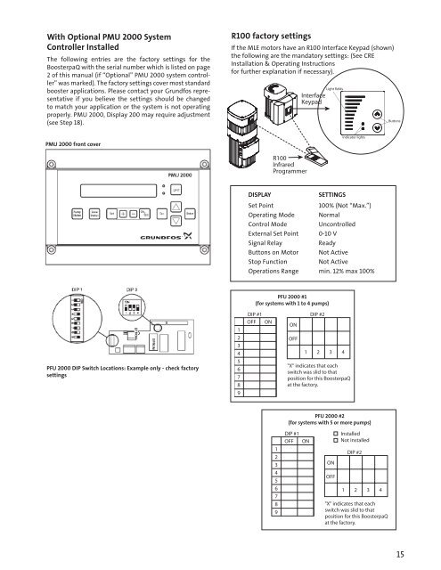
With Optional PMU 2000 System<br />
Controller Installed<br />
The following entries are the factory settings for the<br />
<strong>Booster</strong>paQ with the serial number which is listed on page<br />
2 of this manual (if “Optional” PMU 2000 system controller”<br />
was marked). The factory settings cover most standard<br />
booster applications. Please contact your <strong>Grundfos</strong> representative<br />
if you believe the settings should be changed<br />
to match your application or the system is not operating<br />
properly. PMU 2000, Display 200 may require adjustment<br />
(see Step 18).<br />
R100 factory settings<br />
If the MLE motors have an R100 Interface Keypad (shown)<br />
the following are the mandatory settings: (See <strong>CR</strong>E<br />
Installation & Operating Instructions<br />
for further explanation if necessary).<br />
PMU 2000 front cover<br />
DISPLAY<br />
SETTINGS<br />
Set Point<br />
100% (Not “Max.”)<br />
Operating Mode Normal<br />
Control Mode<br />
Uncontrolled<br />
External Set Point 0-10 V<br />
Signal Relay<br />
Ready<br />
Buttons on Motor Not Active<br />
Stop Function<br />
Not Active<br />
Operations Range min. 12% max 100%<br />
PFU 2000 DIP Switch Locations: Example only - check factory<br />
settings<br />
1<br />
2<br />
3<br />
4<br />
5<br />
6<br />
7<br />
8<br />
9<br />
PFU 2000 #1<br />
(for systems with 1 to 4 pumps)<br />
DIP #1 DIP #2<br />
OFF ON<br />
ON<br />
OFF<br />
1 2 3 4<br />
"X" indicates that each<br />
switch was slid to that<br />
position for this <strong>Booster</strong>paQ<br />
at the factory.<br />
PFU 2000 #2<br />
(for systems with 5 or more pumps)<br />
1<br />
2<br />
3<br />
4<br />
5<br />
6<br />
7<br />
8<br />
9<br />
DIP #1<br />
OFF ON<br />
ON<br />
OFF<br />
Installed<br />
Not installed<br />
DIP #2<br />
1 2 3 4<br />
"X" indicates that each<br />
switch was slid to that<br />
position for this <strong>Booster</strong>paQ<br />
at the factory.<br />
15