BoosterpaQ® Grundfos CR-Booster Systems 60 Hz
BoosterpaQ® Grundfos CR-Booster Systems 60 Hz
BoosterpaQ® Grundfos CR-Booster Systems 60 Hz
You also want an ePaper? Increase the reach of your titles
YUMPU automatically turns print PDFs into web optimized ePapers that Google loves.
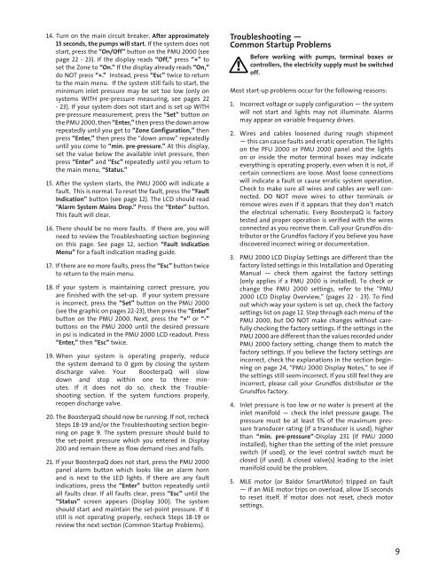
14. Turn on the main circuit breaker. After approximately<br />
15 seconds, the pumps will start. If the system does not<br />
start, press the “On/Off” button on the PMU 2000 (see<br />
page 22 - 23). If the display reads “Off,” press “+” to<br />
set the Zone to “On.” If the display already reads “On,”<br />
do NOT press “+.” Instead, press “Esc” twice to return<br />
to the main menu. If the system still fails to start, the<br />
minimum inlet pressure may be set too low (only on<br />
systems WITH pre-pressure measuring, see pages 22<br />
- 23). If your system does not start and is set up WITH<br />
pre-pressure measurement, press the “Set” button on<br />
the PMU 2000, then “Enter,” then press the down arrow<br />
repeatedly until you get to “Zone Configuration,” then<br />
press “Enter,” then press the “down arrow” repeatedly<br />
until you come to “min. pre-pressure.” At this display,<br />
set the value below the available inlet pressure, then<br />
press “Enter” and “Esc” repeatedly until you return to<br />
the main menu, “Status.”<br />
15. After the system starts, the PMU 2000 will indicate a<br />
fault. This is normal. To reset the fault, press the “Fault<br />
Indication” button (see page 12). The LCD should read<br />
“Alarm System Mains Drop.” Press the “Enter” button.<br />
This fault will clear.<br />
16. There should be no more faults. If there are, you will<br />
need to review the Troubleshooting section beginning<br />
on this page. See page 12, section “Fault Indication<br />
Menu” for a fault indication reading guide.<br />
17. If there are no more faults, press the “Esc” button twice<br />
to return to the main menu.<br />
18. If your system is maintaining correct pressure, you<br />
are finished with the set-up. If your system pressure<br />
is incorrect, press the “Set” button on the PMU 2000<br />
(see the graphic on pages 22-23), then press the “Enter”<br />
button on the PMU 2000. Next, press the “+” or “-”<br />
buttons on the PMU 2000 until the desired pressure<br />
in psi is indicated in the PMU 2000 LCD readout. Press<br />
“Enter,” then “Esc” twice.<br />
19. When your system is operating properly, reduce<br />
the system demand to 0 gpm by closing the system<br />
discharge valve. Your <strong>Booster</strong>paQ will slow<br />
down and stop within one to three minutes.<br />
If it does not do so, check the Troubleshooting<br />
section. If the system functions properly,<br />
reopen discharge valve.<br />
20. The <strong>Booster</strong>paQ should now be running. If not, recheck<br />
Steps 18-19 and/or the Troubleshooting section beginning<br />
on page 9. The system pressure should build to<br />
the set-point pressure which you entered in Display<br />
200 and remain there as flow demand rises and falls.<br />
21. If your <strong>Booster</strong>paQ does not start, press the PMU 2000<br />
panel alarm button which looks like an alarm horn<br />
and is next to the LED lights. If there are any fault<br />
indications, press the “Enter” button repeatedly until<br />
all faults clear. If all faults clear, press “Esc” until the<br />
“Status” screen appears (Display 100). The system<br />
should start and maintain the set-point pressure. If it<br />
still is not operating properly, recheck Steps 18-19 or<br />
review the next section (Common Startup Problems).<br />
Troubleshooting —<br />
Common Startup Problems<br />
Before working with pumps, terminal boxes or<br />
controllers, the electricity supply must be switched<br />
off.<br />
Most start-up problems occur for the following reasons:<br />
1. Incorrect voltage or supply configuration — the system<br />
will not start and lights may not illuminate. Alarms<br />
may appear on variable frequency drives.<br />
2. Wires and cables loosened during rough shipment<br />
— this can cause faults and erratic operation. The lights<br />
on the PFU 2000 or PMU 2000 panel and the lights<br />
on or inside the motor terminal boxes may indicate<br />
everything is operating properly, even when it is not, if<br />
certain connections are loose. Most loose connections<br />
will indicate a fault or cause erratic system operation.<br />
Check to make sure all wires and cables are well connected.<br />
DO NOT move wires to other terminals or<br />
remove wires even if it appears that they don’t match<br />
the electrical schematic. Every <strong>Booster</strong>paQ is factory<br />
tested and proper operation is verified with the wires<br />
connected as you receive them. Call your <strong>Grundfos</strong> distributor<br />
or the <strong>Grundfos</strong> factory if you believe you have<br />
discovered incorrect wiring or documentation.<br />
3. PMU 2000 LCD Display Settings are different than the<br />
factory listed settings in this Installation and Operating<br />
Manual — check them against the factory settings<br />
(only applies if a PMU 2000 is installed). To check or<br />
change the PMU 2000 settings, refer to the “PMU<br />
2000 LCD Display Overview,” (pages 22 - 23). To find<br />
out which way your system is set up, check the factory<br />
settings list on page 12. Step through each menu of the<br />
PMU 2000, but DO NOT make changes without carefully<br />
checking the factory settings. If the settings in the<br />
PMU 2000 are different than the values recorded under<br />
PMU 2000 factory setting, change them to match the<br />
factory settings. If you believe the factory settings are<br />
incorrect, check the explanations in the section beginning<br />
on page 24, “PMU 2000 Display Notes,” to see if<br />
the settings still seem incorrect. If you still feel they are<br />
incorrect, please call your <strong>Grundfos</strong> distributor or the<br />
<strong>Grundfos</strong> factory.<br />
4. Inlet pressure is too low or no water is present at the<br />
inlet manifold — check the inlet pressure gauge. The<br />
pressure must be at least 5% of the maximum pressure<br />
transducer rating (if a transducer is used), higher<br />
than “min. pre-pressure”-Display 231 (if PMU 2000<br />
installed), higher than the setting of the inlet pressure<br />
switch (if used), or the level control switch must be<br />
closed (if used). A closed valve(s) leading to the inlet<br />
manifold could be the problem.<br />
5. MLE motor (or Baldor SmartMotor) tripped on fault<br />
— if an MLE motor trips on overload, allow 15 seconds<br />
to reset itself. If motor does not reset, check motor<br />
settings.<br />
9


