BoosterpaQ® Grundfos CR-Booster Systems 60 Hz
BoosterpaQ® Grundfos CR-Booster Systems 60 Hz
BoosterpaQ® Grundfos CR-Booster Systems 60 Hz

Create successful ePaper yourself
Turn your PDF publications into a flip-book with our unique Google optimized e-Paper software.
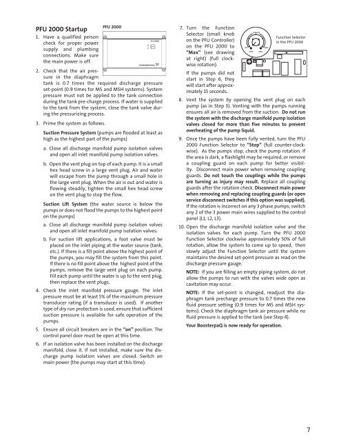
PFU 2000 Startup<br />
1. Have a qualified person<br />
check for proper power<br />
supply and plumbing<br />
connections. Make sure<br />
the main power is off.<br />
2. Check that the air pressure<br />
in the diaphragm<br />
tank is 0.7 times the required discharge pressure<br />
set-point (0.9 times for MS and MSH systems). System<br />
pressure must not be applied to the tank connection<br />
during the tank pre-charge process. If water is supplied<br />
to the tank from the system, close the tank valve during<br />
the pressurizing process.<br />
3. Prime the system as follows.<br />
PFU 2000<br />
Suction Pressure System (pumps are flooded at least as<br />
high as the highest part of the pumps)<br />
a. Close all discharge manifold pump isolation valves<br />
and open all inlet manifold pump isolation valves.<br />
b. Open the vent plug on top of each pump. It is a small<br />
hex head screw in a large vent plug. Air and water<br />
will escape from the pump through a small hole in<br />
the large vent plug. When the air is out and water is<br />
flowing steadily, tighten the small hex head screw<br />
on the vent plug to stop the flow.<br />
Suction Lift System (the water source is below the<br />
pumps or does not flood the pumps to the highest point<br />
on the pumps)<br />
a. Close all discharge manifold pump isolation valves<br />
and open all inlet manifold pump isolation valves.<br />
b. For suction lift applications, a foot valve must be<br />
placed on the inlet piping at the water source (tank,<br />
etc.). If there is a fill point above the highest point of<br />
the pumps, you may fill the system from this point.<br />
If there is no fill point above the highest point of the<br />
pumps, remove the large vent plug on each pump.<br />
Fill each pump until the water is up to the vent plug,<br />
then replace the vent plugs.<br />
4. Check the inlet manifold pressure gauge. The inlet<br />
pressure must be at least 5% of the maximum pressure<br />
transducer rating (if a transducer is used). If another<br />
type of dry run protection is used, ensure that sufficient<br />
suction pressure is available for safe operation of the<br />
pumps.<br />
5. Ensure all circuit breakers are in the “on” position. The<br />
control panel door must be open at this time.<br />
6. If an isolation valve has been installed on the discharge<br />
manifold, close it. If not installed, make sure the discharge<br />
pump isolation valves are closed. Switch on<br />
main power (the pumps may start at this time).<br />
7. Turn the Function<br />
Selector (small knob<br />
on the PFU Controller)<br />
on the PFU 2000 to<br />
“Max” (see drawing<br />
at right) (full clockwise<br />
rotation).<br />
If the pumps did not<br />
start in Step 6, they<br />
will start after approximately<br />
15 seconds.<br />
Setpoint<br />
8. Vent the system by opening the vent plug on each<br />
pump (as in Step 3). Venting with the pumps running<br />
ensures all air is removed from the suction. Do not run<br />
the system with the discharge manifold pump isolation<br />
valves closed for more than five minutes to prevent<br />
overheating of the pump liquid.<br />
9. Once the pumps have been fully vented, turn the PFU<br />
2000 Function Selector to “Stop” (full counter-clockwise).<br />
As the pumps stop, check the pump rotation. If<br />
the area is dark, a flashlight may be required, or remove<br />
a coupling guard on each pump for better visibility.<br />
Disconnect main power when removing coupling<br />
guards. Do not touch the couplings while the pumps<br />
are turning as injury may result. Replace all coupling<br />
guards after the rotation check. Disconnect main power<br />
when removing and replacing coupling guards (or open<br />
service disconnect switches if this option was supplied).<br />
If the rotation is incorrect on any 3 phase pumps, switch<br />
any 2 of the 3 power main wires supplied to the control<br />
panel (L1, L2, L3).<br />
10. Open the discharge manifold isolation valve and the<br />
isolation valves for each pump. Turn the PFU 2000<br />
Function Selector clockwise approximately 50% of full<br />
rotation, allow the system to come up to speed, then<br />
slowly adjust the Function Selector until the system<br />
maintains the desired set-point pressure as read on the<br />
discharge pressure gauge.<br />
NOTE: If you are filling an empty piping system, do not<br />
allow the pumps to run with the valves wide open as<br />
cavitation may occur.<br />
NOTE: If the set-point is changed, readjust the diaphragm<br />
tank precharge pressure to 0.7 times the new<br />
fluid pressure setting (0.9 times for MS and MSH systems).<br />
Check the diaphragm tank air pressure while no<br />
fluid pressure is applied to the tank (see Step 4).<br />
Your <strong>Booster</strong>paQ is now ready for operation.<br />
0%<br />
STOP<br />
MAX<br />
100%<br />
Function Selector<br />
in the PFU 2000<br />
7