Gate 1 Instructions - SEA (UK)
Gate 1 Instructions - SEA (UK)
Gate 1 Instructions - SEA (UK)

Create successful ePaper yourself
Turn your PDF publications into a flip-book with our unique Google optimized e-Paper software.
®<br />
Sistemi Elettronici<br />
di Apertura Porte e Cancelli<br />
International registered trademark n. 804888<br />
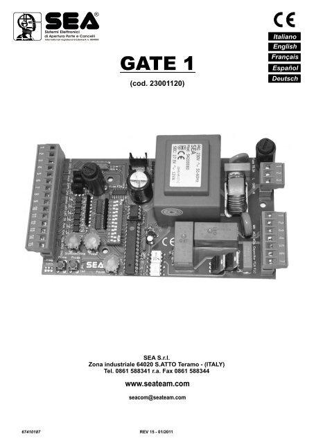
GATE 1<br />
(cod. 23001120)<br />
Italiano<br />
English<br />
Français<br />
Español<br />
Deutsch<br />
<strong>SEA</strong> S.r.l.<br />
Zona industriale 64020 S.ATTO Teramo - (ITALY)<br />
Tel. 0861 588341 r.a. Fax 0861 588344<br />
www.seateam.com<br />
seacom@seateam.com<br />
67410187<br />
REV 15 - 01/2011
®<br />
Sistemi Elettronici<br />
di Apertura Porte e Cancelli<br />
International registered trademark n. 804888<br />
INDICE / INDEX<br />
Italiano<br />
DATI TECNICI..................................................................................................................................................................................3<br />
CONNESSIONI ................................................................................................................................................................................4<br />
DIP SWITCHES E LOGICHE DI PROGRAMMAZIONE ..................................................................................................................5<br />
IMPOSTAZIONI DIP ALTRE FUNZIONI...........................................................................................................................................6<br />
REGOLAZIONI DEI TRIMMER E LETTURA DEI LED ....................................................................................................................7<br />
CONNESSIONI RICEVITORE RADIO, STOP, START ....................................................................................................................8<br />
FOTOCELLULA, LAMPADA SPIA, ACCESSORI SU INGRESSO AUX ..........................................................................................9<br />
CONNESSIONI, ANTENNA, FINECORSA, ENCODER (ANTISCHIACCIAMENTO)....................................................................10<br />
CONNESSIONE MOTORE, CONDENSATORE, LAMPEGGIATORE ...........................................................................................11<br />
CONNESSIONE DEL CAVO DI RETE E MESSA A TERRA, LUCE DI CORTESIA ......................................................................12<br />
AUTOAPPRENDIMENTO PER CANCELLI SCORREVOLI CON FINECORSA ...........................................................................13<br />
AUTOAPPRENDIMENTO PER CANCELLI SCORREVOLI SENZA FINECORSA........................................................................15<br />
PROGRAMMAZIONE DEI TRASMETTITORI ...............................................................................................................................16<br />
CONNESSIONE SPIRE MAGNETICHE........................................................................................................................................17<br />
CONNESSIONE MODULO TRIFASE............................................................................................................................................18<br />
RISOLUZIONE DEI PROBLEMI ....................................................................................................................................................19<br />
AVVERTENZE E GARANZIA.........................................................................................................................................................19<br />
CONDIZIONI DI VENDITA .............................................................................................................................................................89<br />
English<br />
TECHNICAL DATA.........................................................................................................................................................................20<br />
CONNECTIONS.............................................................................................................................................................................21<br />
DIP SWITCHES, LOGIC PROGRAM.............................................................................................................................................22<br />
DIP ADJUSTMENT OTHER FUNCTIONS.....................................................................................................................................23<br />
TRIMMER REGULATION, LEDS...................................................................................................................................................24<br />
RADIO RECEIVER, STOP BUTTON, START BUTTON CONNECTIONS ....................................................................................25<br />
PHOTOCELLS, BUZZER, ACCESSORIES ON AUX ENTRY .......................................................................................................26<br />
ANTENNA, LIMIT SWITCHES, ENCODER (REVERSING SENSOR) CONNECTIONS...............................................................27<br />
MOTOR, CAPACITOR, FLASHING LAMP CONNECTIONS.........................................................................................................28<br />
POWER SUPPLY AND GROUND CONNECTIONS, COURTESY LIGHT ....................................................................................29<br />
SELF-LEARNING OF OPERATING TIME FOR SLIDING GATES (WITH LIMIT SWITCH) ..........................................................30<br />
SELF-LEARNING OF OPERATING TIME FOR SLIDING GATES (WITHOUT LIMIT SWITCH)...................................................32<br />
PROGRAMMING A TRANSMITTER..............................................................................................................................................33<br />
SAFETY LOOP CONNECTION .....................................................................................................................................................34<br />
THREE-PHASE MODULE CONNECTION ....................................................................................................................................35<br />
TROUBLESHOOTING ...................................................................................................................................................................36<br />
WARNINGS AND WARRANTY......................................................................................................................................................36<br />
TERMS OF SALE ..........................................................................................................................................................................90<br />
Français<br />
SPECIFICATIONS TECHNIQUES .................................................................................................................................................37<br />
CONNEXIONS ...............................................................................................................................................................................38<br />
DIP SWITCH ET LOGIQUES DE PROGRAMMATION ................................................................................................................39<br />
AFFICHAGE DIP AUTRES FONCTIONS ....................................................................................................................................40<br />
REGLAGE DES TRIMMER ET LECTURE DES LED ....................................................................................................................41<br />
CONNEXIONS RECEPTEUR RADIO, STOP, START...................................................................................................................42<br />
PHOTOCELLULE, LAMPE TEMOIN, ACCES SUR ENTREE AUX............................................................................................. 43<br />
CONNEXIONS, ANTENNE, FIN DE COURSE, ENCODEUR (ANTI-ECRASEMENT) ................................................................44<br />
CONNEXION MOTEUR, CAPACITEUR, LAMPE CLIGNOTANTE ...............................................................................................45<br />
CONNEXION DU CABLE DU RES<strong>SEA</strong>U ET MISE A LA TERRE, LAMPE DE COURTOISIE......................................................46<br />
AUTOAPPRENTISSAGE POUR PORTAILS COULISSANTS AVEC FIN DE COURSE ...............................................................47<br />
AUTOAPPRENTISSAGE POUR PORTAILS COULISSANTS SANS FIN DE COURSE...............................................................49<br />
PROGRAMMATION DES EMETTEURS .......................................................................................................................................50<br />
CONNEXION SPIRES MAGNETIQUES........................................................................................................................................51<br />
CONNEXIONS MODULE TRIPHASÉ............................................................................................................................................52<br />
RISOLUTIONS DES PROBLEMES ..............................................................................................................................................53<br />
INSTRUCTIONS ET GARANTIE ...................................................................................................................................................53<br />
CONDITION DE VENTE ................................................................................................................................................................89<br />
2<br />
67410187<br />
REV 15 - 01/2011
®<br />
Sistemi Elettronici<br />
di Apertura Porte e Cancelli<br />
International registered trademark n. 804888<br />
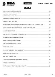
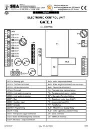
TECHNICAL DATA<br />
English<br />
Automatic Logic<br />
CN1<br />
CN2<br />
Manual Logic<br />
F1<br />
GATE 1 CONTROL UNIT<br />
Partial start<br />
Safety Logic<br />
Automatic Logic 1<br />
Automatic Logic 2<br />
Photocell management in opening<br />
Timer control<br />
Pre-flashing<br />
Warning light<br />
Pause time adjusting<br />
Encoder administration<br />
with inversion on obstacles<br />
Warning lamp<br />
Motor torque regulation<br />
CF CNE<br />
CMR<br />
T1<br />
CN4<br />
U2<br />
DIP<br />
RL2<br />
RL1<br />
U1<br />
Rv3<br />
Limit switch control<br />
Slow down adjustment and administration<br />
Adjustment leaf delay in opening<br />
and closing<br />
Photocells auto-testing<br />
F2<br />
LD11<br />
LD1<br />
LD2<br />
LD3<br />
LD4<br />
LD5<br />
LD6<br />
LD7<br />
LD8<br />
LD9<br />
Rv1<br />
Rv2<br />
LDP<br />
P2<br />
P1<br />
CNP<br />
CN3<br />
LD1 = Warning light<br />
LD2 = TX Photocell power supply<br />
LD3 = 24V Auxiliary<br />
LD4 = Photocell<br />
LD5 = Limit switch in opening<br />
LD6 = Limit switch in closing<br />
LD7 = Start<br />
LD8 = Auxiliary input<br />
LD9 = Encoder<br />
LDP = Programming<br />
LD11 = Stop<br />
CN1 = 230V power supply connector<br />
CN2 = Motor and Flashing lamp connector<br />
CN3 = 24V input / output connector<br />
CN4 = 24V~ Photosync connector<br />
CNP = PALM connector<br />
Rv1 = Trimmer torque adjustment<br />
Rv2 = Trimmer slow down duration adjustment<br />
Rv3 = Trimmer regolazione pausa<br />
P1 = Pushbutton time selflearning<br />
P2 = Pushbutton radio control learning<br />
DIP = Dip-switch Function Setting<br />
F1 = Output and motor fuse (6,3 AT)<br />
F2 = Accessories fuse (1 A)<br />
T1 = Transformer<br />
RL1 = Motor Power Supply Relay<br />
RL2 = Motor Operating Direction Relay<br />
U1 = Micro-controller<br />
U2 = EEPROM memory<br />
CMR = Receiver module connector<br />
CF = Limit switch connector<br />
CNE = Encoder connector<br />
20<br />
67410187<br />
REV 15 - 01/2011
24V<br />
Com m on<br />
C losi n g<br />
Ope ning<br />
Pha s e<br />
Ground<br />
N eu tr a l<br />
®<br />
Sistemi Elettronici<br />
di Apertura Porte e Cancelli<br />
International registered trademark n. 804888<br />
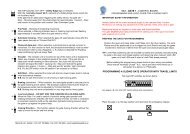
CONNECTIONS<br />
English<br />
CN3<br />
1 2 3 4 5 6 7 8 9 10 11 12 13 14 15<br />
CN1<br />
1 2 3<br />
PSTO<br />
AERIAL<br />
NEG AT IVE<br />
24V War n in lig<br />
ht<br />
24 V Au x il ia<br />
ry<br />
Li m it s witc h o pe nin<br />
g<br />
2 4V TX P h otocel l<br />
Outpu t 1 0 0m A<br />
NEGAT I VE<br />
(se e pag e 23)<br />
300 mA Max<br />
3W Max<br />
50 mA Max<br />
Ph ot o cel l<br />
START<br />
Aux i liary I nput<br />
( se e pag e 23)<br />
EN C O D ER<br />
NEGAT I VE<br />
Limit s wi tc h closin g<br />
Note 1: The 24V Aux supplies 24 V during the whole movement of the gate and during the pause when in<br />
automatic logic, while in semiautomatic logic only during the gate movement. On this output it is possible to connect<br />
a relay with 24V spool for the activation of a contact for generic use.<br />
1 2 3 4 5 6 7 8 9 10 11 12<br />
DIP<br />
ON<br />
CNP<br />
CMR<br />
ON = Function active<br />
Operating logic<br />
Auxiliary input configuration<br />
Pre-flashing<br />
Automatic closing<br />
Photocell autotest<br />
Encoder activation<br />
“Soft” start<br />
Brake (slow-down)<br />
Leaf locking<br />
Closing direction<br />
CNF CNE<br />
Note2: for motors where the limit<br />
switch and the Encoder are precabled<br />
you must not make a<br />
jumper on the limit switches on<br />
the connector and must not use<br />
the contacts of the Encoder.<br />
If the control unit is used without<br />
limit switches, these don't have to<br />
be bridged.<br />
1 2 3 4 5 6 7<br />
~<br />
M<br />
CN2<br />
Note3: On the 24V Ph output it is possible to connect a relay for the timed activation of a courtesy light (see pag. 29)<br />
CN4<br />
1 2<br />
24V~<br />
Note: For the<br />
power supply<br />
of the<br />
synchronized<br />
photocells.<br />
Capaci t or<br />
220<br />
V<br />
F la s h in g lam<br />
p<br />
50W Max<br />
67410187<br />
REV 15 - 01/2011<br />
21
®<br />
Sistemi Elettronici<br />
di Apertura Porte e Cancelli<br />
International registered trademark n. 804888<br />
DIP SWITCHES, LOGIC PROGRAM<br />
English<br />
DIP SWITCHES<br />
ON<br />
1 2 3 4 5 6 7 8 9 10 11 12<br />
WORKING LOGICS<br />
Four different working logics can be selected.<br />
The programming takes place using DIP1 and DIP2.<br />
1 2<br />
1 2 1 2 1 2<br />
DIP<br />
ON<br />
- MANUAL LOGIC<br />
A START command opens the gate, a second START while it is opening stops the motor, a further start impulse<br />
closes. With closed gate a start closes again, a START command while it is closing stops the motor, a further start<br />
opens again.<br />
P. N.: For automatic closing, set DIP SWITCH 6 to the ON position.<br />
- SAFETY LOGIC<br />
A START command opens the gate. A second START while it is opening reverses the motor. With open gate a start<br />
closes the gate again, a START command while it is closing reverses the motor.<br />
- AUTOMATIC LOGIC 1<br />
A START command opens the gate. A second START while it is opening is not accepted. A start in pause is not<br />
accepted, at the en dof the pause the gate closes , a START while it is closing reverses the direction.<br />
P. N.: For automatic closing, set DIP SWITCH 6 to the ON position.<br />
P.N.: When not activated the dip 6 (automatic re-closing) the start impulse during the pause is accepted.<br />
- AUTOMATIC LOGIC 2<br />
A START command opens the gate. A second START is not accepted. A START during the pause time closes the<br />
gate immediately. A START while it is closing reverses the direction.<br />
P. N.: for automatic closing, set DIP SWITCH 6 to the ON position.<br />
DIP1 AND DIP2 PROGRAMMING FOR THE SELECTION OF THE WORKING LOGIC<br />
1 / 2<br />
1 / 2<br />
1 / 2<br />
1 / 2<br />
OFF / OFF<br />
ON / OFF<br />
OFF / ON<br />
ON / ON<br />
If Dip1 and Dip2 are programmed in this way, the control unit will work with Manual Logic<br />
If Dip1 and Dip2 are programmed in this way, the control unit will work with Safety Logic<br />
If Dip1 and Dip2 are programmed in this way, the control unit will work with Automatic 1 Logic<br />
If Dip1 and Dip2 are programmed in this way, the control unit will work with Automatic 2 Logic<br />
22<br />
67410187<br />
REV 15 - 01/2011
®<br />
Sistemi Elettronici<br />
di Apertura Porte e Cancelli<br />
International registered trademark n. 804888<br />
DIP ADJUSTMENT OTHER FUNCTIONS<br />
English<br />
DIP<br />
3 / 4<br />
3 / 4<br />
3 / 4<br />
3 / 4<br />
OPENED<br />
CLOSED<br />
OFF / OFF<br />
ON / OFF<br />
OFF / ON<br />
ON / ON<br />
DIP 3 AND DIP 4 PROGRAMMING FOR AUXILIARY INPUT CONFIGURATION<br />
SAFETY EDGE (N.C. contact)<br />
With dip 3 and dip 4 on OFF the AUX input is activated and works as security edge. When the security edge is<br />
connected to the AUX input, and the contact of the edge opens, the gate reverses the motor about 1 sec. A<br />
START command is required to restart movement.<br />
! ATTENTION: If you choose this configuration, it is necessary to put a jumper between clamps 11 and 14 of CN3.<br />
TIMER (N.O. contact)<br />
If a TIMER is connected to this input, it is possible to open the gate and hold it open for as long as the contact<br />
remains closed. Using a 24 hour or a 7 day timer, openings time can be scheduled exactly as required. When<br />
the TIMER contact is open the motor operates following the operating logics previously set. Do not use this<br />
configuration (active) when not connected to a Timer.<br />
AUXILIARY PHOTOCELL (N.C. contact)<br />
The intervention of this Photocell contact stops the operator until the obstacle is removed. If it’s verified while<br />
the gate is opening, movement resumes in the same direction; if it’s verified while closing, the direction is<br />
reversed. With PALM device it can work as FOTOSTOP, or if occupied it prevents the gate to open and for the<br />
remaining opening it doesn't intervene.<br />
! ATTENTION: If you choose this configuration, it is necessary to put a jumper between clamps 11 and 14 of CN3.<br />
PARTIAL OPENING (N.O. contact)<br />
On this command, the gate opens partially, for about 10 seconds.<br />
The opening time can be changed through the PALM device.<br />
DIP<br />
5<br />
6<br />
7<br />
8<br />
9<br />
OPENED<br />
CLOSED<br />
ON<br />
ON<br />
ON<br />
ON<br />
ON<br />
PROGRAMMING OF OTHER DIPS FOR OTHER FUNCTIONS<br />
PRE-FLASHING<br />
When this function is activated, the flashing lamp and warning light begin flashing about 3 seconds before the<br />
motor starts opening, whether in opening or closing.<br />
AUTOMATIC CLOSING<br />
When activated, the motor automatically closes the gate after the PAUSE time set by trimmer Rv3. This function<br />
can be activated independently from the operating logic set.(DIP SWITCH 1 & 2).<br />
PHOTOCELL AUTOTEST<br />
When this function is activated, a test on the photocells is carried out prior to any movement of the gate. In order<br />
to use this function, the transmitting photocells must be connected to terminals 5 (24V) and 2 (Negative) on the<br />
CN3 connector. In the event of a malfunctioning, the flashing lamp and warning light will both flash slowly. It is<br />
possible to connect a relay to this exit for the courtesy lamp administration.<br />
ENCODER MANAGEMENT (REVERSING SENSOR)<br />
Setting dip 8 on ON the inversion on obstacle with Encoder is activated. Such sensor, in case of obstacle,<br />
reverses the motion for about one second, stops and waits for new commands. In the event of a malfunctioning,<br />
the flashing lamp and warning light will both flash slowly. On the following start the automation will open or close<br />
slowly up to the attainment of one of the stops.<br />
P.N: if no ENCODER is installed, set DIP 8 on OFF. The Encoder sensitivity is adjustable through the<br />
PALM device or through the pushbuttons Ptime and Pcode on board of the control unit.<br />
“SOFT” START<br />
When activated, the motor will start at a lower torque level, to avoid stresses and strains on the mechanical<br />
components of the gate. The starting torque is a percentage of the normal operating torque. P.N.: When the<br />
gate is very heavy or does not run smoothly, it is advised NOT TO activate this function.<br />
10<br />
11<br />
12<br />
67410187<br />
ON<br />
ON<br />
ON<br />
BRAKING (slow-down) AT LIMIT SWITCH<br />
When activated, the motor speed is reduced before reaching the limit switch or the end of the operating time.<br />
The purpose of this function is to bring the leaf gently towards the stop position to avoid a noisy collision. The<br />
closing speed is fixed, but the slow-down time is adjustable, using the Rv2 trimmer.<br />
LEAF LOCKING<br />
When activated, after slowing down, and when the leaf has reached the mechanical stop, for about 1 second<br />
the motor is supplied at the maximum power. This increases the oil pressure in the motor, making the hydraulic<br />
lock more effective. In case of use of the automation, the function (when activated) will be repeated in intervales<br />
of one hour more or less.<br />
IMPORTANT NOTE:<br />
This function SHOULD NOT be activated when used on sliding gates, as it can cause the<br />
!<br />
gate over-running of the limit switches and the motor jamming<br />
Note2: With the Palm through the function PushOpen it is possible to exclude the tightening of the<br />
leaf during the opening phase.<br />
CLOSING DIRECTION<br />
This function allows to define the gate closing direction without reversing the Motor wiring connections and the<br />
Limit Switch contacts.<br />
Note: do not activate this Dip when the motor is working.<br />
23<br />
REV 15 - 01/2011
®<br />
Sistemi Elettronici<br />
di Apertura Porte e Cancelli<br />
International registered trademark n. 804888<br />
TRIMMER REGULATION, LEDS<br />
English<br />
Rv1<br />
Rv2<br />
Rv3<br />
-<br />
P.N.: TIMES AND VALUES ARE<br />
INCREASED BY ROTATING<br />
THE TRIMMERS CLOCKWISE<br />
+<br />
Rv1<br />
OPERATING TORQUE ADJUSTMENT<br />
This Trimmer allows to adjust the motor<br />
torque. This adjustment is needed for<br />
operators without mechanical or<br />
hydraulic anti-crush safety devices.<br />
Regulation should be carried out to avoid<br />
any risks of crushing either people or<br />
objects and, in any case, compliant with<br />
current legislation on the subject.<br />
Rv2<br />
BRAKE (slow-down) LENGTH<br />
ADJUSTMENT<br />
This Trimmer allows to adjust the length of<br />
the slow-down<br />
Rv3<br />
PAUSE LENGTH ADJUSTMENT<br />
This Trimmer allows the adjustment of the<br />
PAUSE time between 0 and 120 seconds.<br />
Set DIP SWITCH 6 to the ON position to<br />
enable automatic closing.<br />
LED1<br />
LED2<br />
LED3<br />
LED4<br />
LED5<br />
LED6<br />
LED7<br />
LED8<br />
LED9<br />
LEDP<br />
LED11<br />
LED1 (TROUBLESHOOTING LED)<br />
This led follows the flashing logic of the control lamp including the alarms’ signalisation.<br />
LED2 (TX PHOTOCELL POWER SUPPLY)<br />
LED3 (24V AUX POWER SUPPLY)<br />
LED4 (PHOTOCELL): When the photocell is occupied the led is switched off<br />
LED5 and LED6 (OPENING LIMIT SWITCH) / (CLOSING LIMIT SWITCH): Switched off leds means that the limit switch<br />
is occupied<br />
LED8 (AUX INPUT)<br />
LED9 (ENCODER)<br />
LEDP (PROGRAMMING)<br />
LED11 (STOP): When connected the led is switched on<br />
ALARM INDICATION BOARD ON CONTROL UNITS GATE<br />
The sequence of lightning, intervals of pause, are shown on the flashlight (for ca. 20 sec.) and on the control lamp (until a new<br />
START).<br />
Number of lightning<br />
Type of alarm<br />
Number of lightning<br />
Type of alarm<br />
1<br />
Photocell<br />
4<br />
Stop<br />
2<br />
Safety edge<br />
5<br />
Photocell self-testing<br />
3<br />
Encoder<br />
6<br />
Triac test<br />
24<br />
67410187<br />
REV 15 - 01/2011
®<br />
Sistemi Elettronici<br />
di Apertura Porte e Cancelli<br />
International registered trademark n. 804888<br />
RADIO RECEIVER, STOP BUTTON,<br />
START BUTTON CONNECTIONS<br />
English<br />
1 2 3 4 5 6 7 8 9<br />
10 11 12 13 14 15<br />
-<br />
+ C<br />
CN3<br />
10<br />
3<br />
2<br />
Com<br />
2<br />
Connection of a radio receiver<br />
Allows to connect an external receiver and to<br />
bettern the range of the radio transmitter. For the<br />
receiver connection make reference to the<br />
related instruction manual.<br />
+ = 24V<br />
- = 0V<br />
C = Contact<br />
Com = Common<br />
13<br />
2<br />
Stop Button<br />
The pressure of this button stops the automation<br />
in whatever condition it can be it needs a start<br />
command (sempre in richiusura) to re-establish<br />
the movement<br />
.<br />
Notice: if it is not used, make a link between<br />
terminals n.13 and 14.<br />
67410187<br />
10<br />
2<br />
10<br />
2<br />
Start Button<br />
An impulse given to this entrance commands<br />
the opening/closing of the automation. It can<br />
be given by a key switch, a loop detector, a<br />
keyboard controller, etc.<br />
To connect the supplied devices (for ex. Loop<br />
detector) see the related instructions.<br />
Timer on the Start Entry:<br />
If the AUX entry (Dip 3 and 4) is not set as TIMER (3 ON / 4 OFF) and the Automatic 1 logic is set (DIP 1 OFF / DIP 2 ON) it is possible to<br />
get the TIMER function through the start contact.<br />
Note 1: The TIMER is active independently from the DIP 6 of automatic reclosing.<br />
Note 2: For all the other functioning logics the TIMER function can be used only through the AUX entry with DIP 3 ON and DIP 4 OFF.<br />
REV 15 - 01/2011<br />
25
®<br />
Sistemi Elettronici<br />
di Apertura Porte e Cancelli<br />
International registered trademark n. 804888<br />
English<br />
PHOTOCELLS, BUZZER,<br />
ACCESSORIES ON AUX ENTRY<br />
1 2 3 4 5 6 7 8 9<br />
10 11 12 13 14 15<br />
-<br />
+<br />
+<br />
C<br />
-<br />
-<br />
Photocell<br />
self-testing<br />
CN3<br />
Photocells Connection<br />
When the photocells beam is crossed, the<br />
automation reverses its movement if in<br />
closing phase.<br />
To use photocell self-testing, connect<br />
positive (+) to terminal 5 instead of 3.<br />
Notice: if it is not used, make a<br />
connection between terminals 7 and 14.<br />
+ = 24V - = 0V C = Contact<br />
Com = Common<br />
3<br />
TX<br />
2<br />
RX<br />
-<br />
+<br />
Com<br />
7<br />
N.C.<br />
Photocells Connection AUX (DIP 3 OFF DIP 4 ON)<br />
The intervention of this Photocell contact stops the<br />
operator until the obstacle is removed. If it’s verified<br />
while the gate is opening, movement resumes in the<br />
same direction; if it’s verified while closing, the direction<br />
is reversed.<br />
With PALM device it can work as FOTOSTOP, or if<br />
occupied it prevents the gate to open and for the<br />
remaining opening it doesn't intervene.<br />
Notice: if it is not used, make a connection between<br />
terminals 11 and 14<br />
+ = 24V - = 0V C = Contact Com = Common<br />
3<br />
TX<br />
2<br />
RX<br />
-<br />
+<br />
Com<br />
11<br />
N.C.<br />
Security light<br />
The connection of the 24V security light allows to follow the function of<br />
the automation in distance as it flashes in the same frequency of the<br />
external warning lamp.<br />
Timer<br />
4<br />
14<br />
Partial Start<br />
Allows the partial opening of the gate for about 10 seconds.<br />
Notice: For the partial opening the contact is a N. O.<br />
contact (Usually opened). To use the partial access,<br />
place dip-switches 3 and 4 on ON.<br />
11<br />
14<br />
With DIP3 on ON and DID4 on<br />
OFF it is possible to connect a<br />
timer. The Timer executes the<br />
timed opening and keeps the<br />
gate open for the whole<br />
adjusted time.<br />
11<br />
14<br />
Safety edge input<br />
The security edge is a (N.C.) contact which once opened causes an inversion of the movement for about one second and has to be<br />
mounted as protection on the principal edge of the gate)<br />
Notice: To use the safety edge, place dip-switches 3 and 4 on OFF.<br />
Notice: This contact can also be used for the connection of the photocell with battery.<br />
! Notice: If not used, but the function has been adjusted, bridge the contact with the negative (ex. 13,15)<br />
26<br />
67410187<br />
REV 15 - 01/2011<br />
11<br />
15
®<br />
Sistemi Elettronici<br />
di Apertura Porte e Cancelli<br />
International registered trademark n. 804888<br />
English<br />
ANTENNA, LIMIT SWITCHES,<br />
ENCODER (reversing sensor)<br />
CONNECTIONS<br />
1 2 3 4 5 6 7 8 9<br />
10 11 12 13 14 15<br />
- +<br />
Com -<br />
LEDP<br />
P2<br />
Brown<br />
White<br />
Green<br />
P1<br />
Cn3<br />
Encoder adjustment procedure on board of the control unit<br />
1. Keep pressed both Ptime and Pcode buttons for 3 seconds until ledP turns on..<br />
2. The led turns on and stays on for 1 second, afterwards it reproduces the number of<br />
flashes corresponding to the level of the set encoder sensibility (from 1 to 15, where<br />
15 stands for the maximum insensibility)<br />
3. If the set level is not suitable, press the push-button Pcode to increase or Ptime to<br />
decrease it. Every impulse corresponds to the increase or the decrease of one unity.<br />
4. After 1 second from the last pressure of the push-button the set sensibility level will<br />
be shown through the corrisponding number of flashes.<br />
5. After 3 seconds from the visualization, the procedure will be left and the ledP<br />
switches off.<br />
Note: Execute the adjustment with still- standing gate.<br />
1-<br />
2<br />
Antenna<br />
Connect the<br />
antenna as in<br />
the picture.<br />
Encoder (reversing sensor)<br />
The encoder is a sensor which allows the inverison of the<br />
movement in case of an obstacle during the run of the gate in both<br />
opening and closing and up to few centimeters from the stop. It is<br />
set in the factory on a middle level but can be modified. Low<br />
sensibility levels do not allow a fast inversion as required by the<br />
En12453 rules. To use this system it is necessary to buy a <strong>SEA</strong><br />
motor provided with encoder. If there are no limit switches, with<br />
active Encoder, whenever there will be a power failure and after<br />
every obstacle, the gate will proceed for one cycle at low speed to<br />
recover the position.<br />
!<br />
Note: When not used, place dip 8 on off.<br />
Note: In case of anomalies of the encoder the warning lamp<br />
and the control lamp will blink slowly.<br />
Limit Switches<br />
Limit Switch 1<br />
They can be of different types:<br />
- inductive limit switch<br />
- mechanical limit switch with lever<br />
- limit switch with spring<br />
- limit switch for motor-reducer with chain.<br />
All these limit switches must be manufactured by<br />
<strong>SEA</strong> for a complete compatibility of the connectors<br />
Com = Common<br />
When the control unit is used without limit<br />
switches it is not necessary to bridge them.<br />
67410187<br />
REV 15 - 01/2011<br />
9<br />
14<br />
Encoder<br />
14<br />
8<br />
Limit Switch 2<br />
3 12 15<br />
27
®<br />
Sistemi Elettronici<br />
di Apertura Porte e Cancelli<br />
International registered trademark n. 804888<br />
English<br />
MOTOR, CAPACITOR, FLASHING LAMP<br />
CN2<br />
CONNECTIONS<br />
Com<br />
C O<br />
1 2 3 4 5 6 7<br />
Flashing Lamp<br />
The warning lamp signals the movement of the gate and<br />
the alarm conditions due to anomalies of the control unit or<br />
itself.<br />
Notice: It is possible to activate a pre-flashing of 3<br />
seconds before activating the automation placing Dip<br />
5 on ON.<br />
6<br />
7<br />
Starting Capacitor<br />
The start condensator allows the motor start,<br />
when not connected it is possible that the motor<br />
does not start.<br />
5<br />
4<br />
Motor<br />
Output for motor connection<br />
O = OPEN<br />
3<br />
C = CLOSED<br />
Com = COMMON<br />
Motor<br />
terminal (CN2)<br />
3<br />
2 1<br />
28<br />
67410187<br />
REV 15 - 01/2011
N.O.<br />
®<br />
POWER SUPPLY AND GROUND CONNECTIONS,<br />
COURTESY LIGHT<br />
CN1<br />
Sistemi Elettronici<br />
di Apertura Porte e Cancelli<br />
International registered trademark n. 804888<br />
The courtesy light remains switched on<br />
for 120sec. after the complete opening<br />
and after the complete closing.<br />
English<br />
Note: This delay is adjustable through<br />
the PALM device and can vary from 15<br />
sec. to 240 sec.<br />
L T N<br />
1 2 3<br />
EXT.P .S .<br />
Courtesy light<br />
connection<br />
F<br />
N<br />
CN3<br />
1 2 3 4 5 6 7<br />
1 2 3 4 5 6 7 8 9<br />
10 11 12 13 14 15<br />
CO M.<br />
- 24V Ph<br />
3CN<br />
2<br />
5<br />
Ground connection<br />
G<br />
G = Ground<br />
Example<br />
- A good ground in a gate operator installation will minimize or<br />
prevent damage to the operator caused by natural events<br />
(lighting, strikes and others)<br />
Net supply input<br />
P = PHASE<br />
N = NEUTRAL<br />
3<br />
2<br />
1<br />
G = GROUND<br />
NOTICE: for the connection to the electric net see the<br />
norms in force.<br />
67410187<br />
REV 15 - 01/2011<br />
29
®<br />
Sistemi Elettronici<br />
di Apertura Porte e Cancelli<br />
International registered trademark n. 804888<br />
English<br />
SELF-LEARNING OF OPERATING TIME<br />
FOR SLIDING GATES (WITH LIMIT SWITCH)<br />
STEP 1:<br />
Make all the electrical connections and jumpers on all N.C. contact.<br />
If an operator equipped with mechanical or hydraulic anti-crush safety device is being used, set the torque (trimmer Rv1) to the<br />
maximum value and adjust the motor torque using the by-pass valves or clutch adjustment screws located on the operator.<br />
If an operator without a mechanical or hydraulic ant-’crush safety system is being used, set the torque to the maximum value<br />
ONLY for the self-learning process.<br />
Immediately afterwards, set a torque value that will ensure anti-crush safety, in accordance with current legislation.<br />
ATTENTION! THIS PROCEDURE IS POTENTIALLY DANGEROUS AND MUST BE CARRIED OUT ONLY BY<br />
SPECIALIZED PERSONNEL USING ALL SAFETY PRECAUTIONS.<br />
STEP 2: Take off the power supply (Fig. 1), release the motor and set the gate in the half open position (Fig. 2).<br />
Re-lock the motor and set the power supply up (Fig. 3)<br />
Fig. 1<br />
OFF<br />
Fig. 2<br />
Fig. 3<br />
ON<br />
30<br />
67410187<br />
REV 15 - 01/2011
®<br />
Sistemi Elettronici<br />
di Apertura Porte e Cancelli<br />
International registered trademark n. 804888<br />
English<br />
SELF-LEARNING OF OPERATING TIME<br />
FOR SLIDING GATES (WITH LIMIT SWITCH)<br />
Note1: When the Encoder is used, set dip 8 on ON<br />
Note 2: Make sure that the Stop, the photocell and<br />
the AUX input, are correctly represented.<br />
Press and hold button P1 (LedP will come on) until<br />
the gate starts closing*.<br />
Release P1<br />
1 2 3 4 5 6 7 8 9 10 1112 13 14 15<br />
CN3<br />
LE D1 1<br />
P1<br />
LED1<br />
LED2<br />
LED3<br />
LED4<br />
LED5<br />
LED6<br />
LED7<br />
LED8<br />
LED9<br />
Rv2<br />
P2<br />
F2<br />
LEDP<br />
Rv1<br />
DIP<br />
Rv3<br />
U2<br />
U1<br />
RL1<br />
T1<br />
RL2<br />
F1<br />
CN1<br />
1 2 3<br />
CN2<br />
1 2 3 4 5 6 7<br />
LEDP<br />
P1<br />
P1<br />
P1<br />
If the motor starts to open the gate, take OFF the power, move DIP SW 12 to opposite position and then repeat STEP 2<br />
*The gate will keep closing until it reaches the closing limit switch (Fig. 6). The motor stops and then immediately begins an<br />
opening cycle (Fig. 7). On reaching the opening limit switch, the motor stops and begins to close once more (Fig. 8) until il<br />
reaches the closing limit switch (Fig. 9). At this point the gate remains closed, the operating times are set and the operator is<br />
ready to work.<br />
Fig. 6 Fig. 7<br />
Fig. 8 Fig. 9<br />
STEP 3: Double check that the operating times have been memorized correctly giving a START or pressing P1. If necessary,<br />
repeat the programming procedure from STEP 2.<br />
STEP 4: If used with an operator without a mechanical or hydraulic anti-crush safety device, adjust trimmer Rv1 to values that<br />
will ensure anti-crush safety, in accordance with current legislation.<br />
Adjust the slow-down length (if enabled), using trimmer Rv2.<br />
67410187<br />
REV 15 - 01/2011<br />
31
®<br />
Sistemi Elettronici<br />
di Apertura Porte e Cancelli<br />
International registered trademark n. 804888<br />
English<br />
SELF-LEARNING OF OPERATING TIME<br />
FOR SLIDING GATES (WITHOUT LIMIT SWITCH)<br />
Note 1: Make sure that the limit switches are not<br />
bridged<br />
Note 2: Make sure that the Stop, the photocell<br />
and the AUX input, are correctly represented.<br />
Press and hold button P1 (LedP will come on) until<br />
the gate starts closing*.<br />
Release P1<br />
1 2 3 4 5 6 7 8 9 10 1112 13 14 15<br />
CN3<br />
L ED1 1<br />
P1<br />
LED1<br />
LED2<br />
LED3<br />
LED4<br />
LED5<br />
LED6<br />
LED7<br />
Rv2<br />
P2<br />
F2<br />
E DL 8<br />
LED9<br />
LEDP<br />
Rv1<br />
DIP<br />
Rv3<br />
U2<br />
U1<br />
RL1<br />
T1<br />
RL2<br />
F1<br />
CN1<br />
1 2 3<br />
CN2<br />
1 2 3 4 5 6 7<br />
LEDP<br />
P1<br />
P1<br />
P1<br />
If the motor starts to open the gate, take OFF the power, move DIP SW 12 to opposite position and then repeat STEP 2<br />
*The gate will keep closing until it reaches the stop in closing (Fig. 10). Once it has reached it press P1 again, now an opening<br />
cycle will start (Fig. 11). When the gate has reached the mechanical stop in opening the motor stops, at this point press P1<br />
again, the gate will execute the closing (Fig.12) until it reaches the stop in closing (Fig.13), at this point press P1 again, now the<br />
selflearning has been concluded.<br />
Note: If the safety gate is installed you must give the impulse exactly on the stop.<br />
Fig. 10 Fig. 11<br />
Fig. 12 Fig. 13<br />
STEP 3: Double check that the operating times have been memorized correctly giving a START or pressing P1. If necessary,<br />
repeat the programming procedure from STEP 2.<br />
STEP 4: If used with an operator without a mechanical or hydraulic anti-crush safety device, adjust trimmer Rv1 to values that<br />
will ensure anti-crush safety, in accordance with current legislation.<br />
Adjust the slow-down length (if enabled), using trimmer Rv2.<br />
32<br />
67410187<br />
REV 15 - 01/2011
®<br />
!<br />
Sistemi Elettronici<br />
di Apertura Porte e Cancelli<br />
International registered trademark n. 804888<br />
PROGRAMMING A TRANSMITTER<br />
WARNING: Make the radio transmitters programming before you connect the antenna and insert the receiver into the<br />
special CMR connector (if available) with turned off control unit. The control unit automatically recognizes if the receiver is a RF<br />
(433 Mhz Cod.23120420, 868 Mhz Cod. 23120425) or RF Roll module (433 Mhz Cod. 23120470, 868 Mhz Cod. 23120480) . Note: With a<br />
RF module it will be possible to use only 12 bit radio transmitters, that are Coccinella Dip and Copy and Smart Dual. With RF Roll<br />
module it will be possible to use only Coccinella Roll radio transmitters.<br />
Note: The auto-recognition of the Roll module will be vaild starting from revision 41D on.<br />
On the preceding revisions it will be possible to insert only the RF module (433 Mhz Cod.23120420, 868 Mhz Cod. 23120425).<br />
RADIO MODULE CONNECTION<br />
Plug the RF or RF Roll receiver module to the CMR connector<br />
PROGRAMMING A TRANSMITTER ON START<br />
Press button P2 (PCode) until LEDP turns ON.<br />
English<br />
P2<br />
12 3 4 56 78 910 1112 13 14 15<br />
CN3<br />
LED11<br />
LED1<br />
LED2<br />
LED3<br />
LED4<br />
Rv2<br />
P1 P2<br />
F2<br />
DLE 5<br />
LED6<br />
LED7<br />
DLE8<br />
LED9<br />
Rv1<br />
DIP<br />
Rv3<br />
ELPD<br />
U2<br />
U1<br />
RL1<br />
T1<br />
RL2<br />
F1<br />
CN1<br />
1 2 3<br />
CN2<br />
1 2 3 4 5 6 7<br />
P2<br />
LEDP<br />
LEDP<br />
Give a START with the transmitter, using the button chosen for the start command.<br />
The LED will flash twice to confirm that the transmitter code has been memorized and will remain ON waiting for further transmitters.<br />
If no further code is memorized within 10 seconds, the LED automatically goes OFF and the programming has to be repeated.<br />
ATTENTION: If the code entered is already in the memory, it will be deleted. LedP flashes 4 times to indicate this procedure.<br />
PROGRAMMING A TRANSMITTER ON PARTIAL START<br />
1) Press button P2 (PCode) until LEDP turns ON.<br />
2) Press button P1 (PTime). LEDP will start to flash quickly<br />
1) 2)<br />
LEDP<br />
LEDP<br />
LEDP<br />
P2<br />
P1<br />
Give a START with the transmitter, using the button chosen for the start command. The LED will flash twice to confirm that the transmitter code<br />
has been memorized and will remain ON waiting for further transmitters.<br />
If no further code is memorized within 10 seconds, the LED automatically goes OFF and exits the programming procedure.<br />
ATTENTION: If the code entered is already in the memory, it will be deleted. Led P flashes 4 times to indicate this procedure.<br />
DELET ALL RADIO TRANSMITTERS<br />
Press and keep pressed push button Pcode, now ledP begins a flashing sequence. Wait until the led stops to blink and release Pcode. Now<br />
ledP will blink for 6 times to confirm the cancellation.<br />
PALM FUNCTIONS:<br />
LED14<br />
LED15<br />
LED16<br />
U2<br />
J1<br />
CN1<br />
U1<br />
Rv3 P1<br />
Rv2<br />
P2<br />
Rv1<br />
F2<br />
LED1<br />
LED2<br />
LED3<br />
LED4<br />
LED5<br />
LED6<br />
LED7<br />
LED8<br />
LED9<br />
LED10<br />
LED11<br />
CN2<br />
LED12<br />
DIP<br />
LED13<br />
CN4<br />
RL1<br />
RL2<br />
CN3<br />
RL3<br />
F1<br />
GATE 1-GATE 2 Administration<br />
• Visualisation and modification of the following parameters:<br />
• Working times<br />
• Leaf delay<br />
• Partial opening time<br />
• 2 n. maintenance cycles adjustment<br />
• Antisqueezing sensibility SAFETY GATE<br />
• Photostop activation<br />
• Reclosing after photocell activation<br />
• Courtesy light time repetition<br />
• Disactivation Push over in opening<br />
67410187<br />
REV 15 - 01/2011<br />
33
®<br />
Sistemi Elettronici<br />
di Apertura Porte e Cancelli<br />
International registered trademark n. 804888<br />
SAFETY LOOP CONNECTION<br />
English<br />
CN3<br />
1 2 3 4 5 6 7 8 9<br />
10 11 12 13 14 15<br />
THIS SCHEME SHOWS HOW TO<br />
CONNECT EVENTUAL<br />
MAGNETIC LOOPS.<br />
This scheme is only valid as a<br />
connection example.<br />
-<br />
+<br />
C2<br />
C1<br />
3 = 24 V<br />
2 = 0 V<br />
EX. Loops’ connection<br />
Loop 1 (security in<br />
exit)<br />
Connecting scheme of<br />
loop detector 1 reader.<br />
7 = Contact photocell<br />
(n.c.)<br />
14 = Common<br />
photocell<br />
Loop1<br />
Loop 1<br />
Loop 2 (start)<br />
Connecting scheme of<br />
loop detector 2 reader.<br />
10 = Contact start (n.o.)<br />
14 = Common<br />
Loop2<br />
Loop 2<br />
Loop 3<br />
Loop3<br />
Loop 3 (start)<br />
Connecting scheme of loop<br />
detector reader.<br />
10 = Contact start (n.o.)<br />
14 = Common<br />
34<br />
67410187<br />
REV 15 - 01/2011
®<br />
Sistemi Elettronici<br />
di Apertura Porte e Cancelli<br />
International registered trademark n. 804888<br />
THREE-PHASE MODULE CONNECTION<br />
English<br />
Power supply connector<br />
for control unit (230V)<br />
23001120 (GATE 1)<br />
1 2 3<br />
1 2 3 4 5 6 7<br />
Motor wiring connector for control unit (230V)<br />
23001120 (GATE 1)<br />
Motor (380V~)<br />
11115005 - 11110055<br />
CN1<br />
U V W<br />
N N F COM. OP. CL.<br />
K1<br />
CN2<br />
Grounding<br />
FST1<br />
Three-phase<br />
power supply<br />
380V~<br />
N R S T<br />
R (2T1)<br />
S (4T2)<br />
T1<br />
T (6T3)<br />
K2<br />
THREE-PHASE<br />
MODULE<br />
K1-K2 = Contactors 230V~ 16A<br />
T1 = Thermal switch (limit 3,7A)<br />
CN1 = Power supply connector for elect. control unit (220V)<br />
CN2 = Power supply connector for motor (380V)<br />
FST1 = Grounding faston<br />
Note: the slow down function (DIP 10), “soft” start (Dip 9) and leaf lock (Dip 11) must be excluded on<br />
the electronic control unit.<br />
The trimmer for the couple adjustment must be set on the maximum value (turn clockwise).<br />
67410187<br />
REV 15 - 01/2011<br />
35
®<br />
Sistemi Elettronici<br />
di Apertura Porte e Cancelli<br />
International registered trademark n. 804888<br />
Advises<br />
Make sure all Safety LED are turned ON<br />
All not-used N.C. contacts must have jumpers<br />
TROUBLESHOOTING<br />
Problem Found Possibile Cause Solutions<br />
Motor doesn't respond to any<br />
start command<br />
<strong>Gate</strong> doesn't move while the<br />
motor is running<br />
A) Jumper missing on one of the N.C. Contacts<br />
B) Receiver doesn’t work (LED 7 in not turned ON)<br />
C) Burnt fuses<br />
D) The Auxiliary contact is set as a N. C. Conntact<br />
A)The Motor is in the Released position<br />
B) The electronic / mechanic Clutch or By-pass<br />
Valve are not set<br />
C) There is an obstacle or the motor has reached<br />
a limit switch<br />
English<br />
A) Check Connections or Jumpers on Contacts<br />
13/14 and 7/2<br />
B) Check connection, polarity and fuse of the receiver<br />
C) Replace burnt fuse on the board<br />
D) Set the Auxiliary contact as a N.O. setting Dip<br />
Switches 3 and 4 in ON position<br />
A) Re-lock the motor<br />
B) Adjust Electronic clutch using Trimmer Rv1 or<br />
Motor Clutch / By-pass Valve<br />
C) Remove obstacle or switch the the operating<br />
direction using Dip Switch 12<br />
<strong>Gate</strong> doesn't reach the<br />
complete Open/Closed<br />
position<br />
The gate opens but doesn’t<br />
close<br />
The gate doesn't close<br />
automatically<br />
A) Wrong setting of the Limit Switches<br />
B) Erron on Programming<br />
C) <strong>Gate</strong> is stopped by an obstacle<br />
A) The photocell Contact 7/2 is not closed<br />
B) The auxiliary contac is set as a N.C.<br />
A) The Automatic Closing is OFF<br />
B) Pause time set to High<br />
A) Set Limit Switches<br />
B) Repeat Programming as on<br />
C) Remove obstacle<br />
A) Check LED or jumpers<br />
B) Set the Auxiliary contact as a N.O. setting Dip<br />
Switch 3 and 4 in ON<br />
A) Activate Automatic Closing by Dip Switch 6<br />
B) Adjust Pause time using Trimmer Rv3<br />
Page for both instaler and user<br />
WARNINGS<br />
The electric installation and the functioning logic choice must agree with the laws in force. In any case you must foresee a 16A and threshold<br />
0.030A differential switch. Keep the power cables (motors, power supply) separate from the command cables (push buttons, photocells and<br />
so on). In order to avoid any interference it’s preferable to foresee and use two separate sheaths.<br />
REPLACEMENTS<br />
Any request for spare parts must be sent to: <strong>SEA</strong> s.r.l. - Zona Ind.le, 64020 S.ATTO - Teramo - Italia<br />
SAFETY AND ENVIRONMENTAL COMPATIBILITY<br />
It’s recommended not to dispel in the environment the packaging materials of products and/or circuits.<br />
STORING<br />
REGULAR PRODUCT DISPOSAL (electric and electronic waste)<br />
(It’s applicable in UE countries and in those ones provided with a differential rubbish collection)<br />
The brand that you find on the product or on documentation signals that the product must not be disposed off together with other domestic<br />
rubbish at the end of life cycle. In order to avoid any possible environmental or health damage because of the irregular waste disposal, we<br />
kindly invite you to separate this product from other kind of rubbish and to recycle it in a responsible way in order to favor the sustainable reuse<br />
of material resorces. Domestic users are invited to contact the retailer where the product has been purchased or the local office in charge for<br />
all the information related to defferential collection and recycling of this kind of product.<br />
WAREHOUSING TEMEPERATURES<br />
T min T Max Dampness min Dampness Max<br />
- 40°C + 85°C 5% not condensing 90% not condensing<br />
Materials handling must be made with appropriate vehicles..<br />
LIMIT OF GUARANTEE<br />
For the guarantee see the sales conditions on the official <strong>SEA</strong> price list.<br />
<strong>SEA</strong> reserves the right to make any required modification or change to the products and/or to this manual without any advanced notice<br />
obligation.<br />
36<br />
67410187<br />
REV 15 - 01/2011
®<br />
67410187<br />
Sistemi Elettronici<br />
di Apertura Porte e Cancelli<br />
International registered trademark n. 804888<br />
CONDIZIONI DI VENDITA<br />
Italiano<br />
EFFICACIA DELLE PRESENTI CONDIZIONI GENERALI DI VENDITA: Le presenti condizioni generali di vendita si applicano a tutti gli ordini<br />
indirizzati a <strong>SEA</strong> s.r.l. Tutte le vendite fatte da <strong>SEA</strong> ai clienti sono regolate secondo le presenti condizioni di vendita che costituiscono parte<br />
integrante del contratto di vendita ed annullano ogni clausola contraria o pattuizioni particolari presenti nell’ ordine o in altro documento<br />
proveniente dall’ acquirente (cliente)<br />
AVVERTENZE GENERALI Gli impianti di automazioni porte e cancelli vanno realizzati esclusivamente con componenti <strong>SEA</strong>, salvo accordi<br />
specifici. L’inosservanza delle norme di sicurezza vigenti (Norm. EUROPEE EN 12453 - EN 12445 e altro) e di buona tecnica esclude la <strong>SEA</strong> da<br />
ogni responsabilità. La <strong>SEA</strong> non risponde del mancato rispetto della corretta e sicura installazione secondo le norme.<br />
1) PROPOSTA D’ORDINE La proposta d’ordine si intenderà accettata solo dopo la sua approvazione da parte della <strong>SEA</strong>. Conseguenza della<br />
sua sottoscrizione, l’acquirente sarà vincolato alla stipula di un contratto d’acquisto, secondo quanto contenuto nella stessa proposta d’ordine e<br />
nelle presenti condizioni di vendita. Viceversa, la mancata comunicazione all’acquirentedell’aprovazione della proposta d’ordine, non comporta<br />
la sua automatica accettazione da parte della <strong>SEA</strong><br />
2) VALIDITÀ OFFERTA Le offerte proposte dalla <strong>SEA</strong> o dalla sua struttura commerciale periferica, avranno una validità di 30 giorni solari, salvo<br />
diversa comunicazione in merito.<br />
3) PREZZI I prezzi della proposta d’ordine sono quelli del listino in vigore alla data della redazione della stessa. Gli sconti applicati dalla struttura<br />
commerciale periferica della <strong>SEA</strong> si intenderanno validi solo dopo la loro accettazione da parte della <strong>SEA</strong>. I prezzi si intendono per merce resa<br />
franco ns. stabilimento in Teramo, esclusi IVA ed imballaggi speciali. La <strong>SEA</strong> si riserva il diritto di modificare in qualsiasi momento il listino, dando<br />
opportuno preavviso alla rete di vendita. Le condizioni speciali riservate agli acquisti con formula agevolata Qx, Qx1, Qx2, Qx3 sono riservate ai<br />
distributori ufficiali dietro accettazione scritta da parte della direzione <strong>SEA</strong>.<br />
4) PAGAMENTI Le forme di pagamento ammesse sono quelle comunicate o accettate di volta in volta dalla <strong>SEA</strong>. Il tasso di interesse sul ritardo<br />
da pagamento è del 1,5% mensile e comunque non oltre il tasso massimo legalmente consentito.<br />
5) CONSEGNA La consegna avverrà indicativamente ma non tassativamente entro 30 giorni lavorativi dalla data di ricezione dell’ordine, salvo<br />
diverse comunicazioni in merito. Il trasporto degli articoli venduti sarà effettuato a spese ed a rischio dell’acquirente. La <strong>SEA</strong> si libera dall’obbligo<br />
della consegna rimettendo la merce al vettore, sia esso scelto dalla <strong>SEA</strong> oppure dall’acquirente. Eventuali smarrimenti e/o danneggiamenti della<br />
merce dovuti al trasporto, sono a carico dell’acquirente.<br />
6) RECLAMI Eventuali reclami e/o contestazioni dovranno pervenire alla <strong>SEA</strong> entro 8 giorni solari dalla ricezione della merce, supportati da<br />
idonei documenti provanti la loro veridicità.<br />
7) FORNITURA L’ordine in oggetto viene assunto da <strong>SEA</strong> senza alcun impegno e subordinatamente alle possibilità di approvvigionamento delle<br />
materie prime occorrenti alla produzione; eventuali mancate esecuzioni totali o parziali non possono dar luogo a reclami e riserve per danni. La<br />
fornitura <strong>SEA</strong> è strettamente limitata alla sola merce di sua produzione, esclusi il montaggio, l’installazione ed il collaudo. La <strong>SEA</strong> declina<br />
pertanto ogni responsabilità per danni che dovessero derivare, anche a terzi, dall’inosservanza delle norme di sicurezza e della buona regola<br />
d’arte nelle fasi dell’installazione e dell’impiego dei prodotti venduti.<br />
8) GARANZIA La garanzia minima è di 12 mesi e può essere estesa, come di seguito, in caso di riconsegna del certificato di garanzia.<br />
SILVER: Le parti meccaniche degli operatori rientranti in tale categoria sono garantite per 24 mesi dalla data di fabbricazione riportata<br />
sull’operatore.<br />
GOLD: Le parti meccaniche degli operatori rientranti in tale categoria sono garantite per 36 mesi dalla data di fabbricazione riportata<br />
sull’operatore.<br />
PLATINUM: Le parti meccaniche degli operatori rientranti in tale categoria sono garantite per 36 mesi dalla data di fabbricazione riportata<br />
sull’operatore. La garanzia di base (36 mesi) sarà estesa per ulteriori 24 mesi (fino ad un totale di 60 mesi) qualora venga acquistato il certificato<br />
di garanzie che dovrà essere compilato e rispedito alla <strong>SEA</strong> s.r.l. entro 60 giorni dall’acquisto. L’elettronica e le centrali di comando sono garantite<br />
per 24 mesi dalla data di fabbricazione. Nell’eventualità di difettosità del prodotto, la <strong>SEA</strong> si impegna alla sua sostituzione gratuita oppure alla sua<br />
riparazione, previa restituzione al proprio centro di riparazione. La definizione di stato di garanzia è ad insindacabile giudizio della <strong>SEA</strong>. I pezzi<br />
sostitutivi restano di proprietà della <strong>SEA</strong>. In modo vincolante, il materiale dell’acquirente ritenuto in garanzia deve essere spedito al centro di<br />
riparazione della <strong>SEA</strong> in porto franco e sarà rispedito dalla <strong>SEA</strong> in porto assegnato. La garanzia non si estende alla manodopera eventualmente<br />
accorsa. I difetti riconosciuti non produrranno alcuna responsabilità e/o richiesta di danni, di qualsiasi natura essi siano, da parte dell’acquirente<br />
nei riguardi della <strong>SEA</strong>. La garanzia non è in ogni caso riconosciuta qualora sia stata apportata alla merce qualsivoglia modifica, oppure vi sia<br />
stato un uso improprio, oppure si sia in presenza di una qualsivoglia sua manomissione o di un montaggio non corretto, oppure se sia stata<br />
rimossa l’etichetta apposta dal produttore comprensiva del marchio <strong>SEA</strong> registrato n° 804888. La garanzia non è inoltre valida nel caso la merce<br />
<strong>SEA</strong> sia stata in parte o in toto accoppiata a componenti meccanici e/o elettronici non originali, ed in particolare in assenza di una specifica<br />
autorizzazione in merito, ed inoltre nel caso in cui l’acquirente non sia in regola con i pagamenti. La garanzia non comprende danni derivati dal<br />
trasporto, materiale di consumo, avarie dovute al mancato rispetto delle specifiche prestazionali dei prodotti indicate nel listino. Non è<br />
riconosciuto alcun indennizzo durante il tempo di riparazione e/o sostituzione della merce in garanzia. La <strong>SEA</strong> declina ogni responsabilità per<br />
danni a cose o persone derivanti dall’inosservanza delle norme di sicurezza e della non conforme installazione o dall’impiego errato dei prodotti<br />
venduti. La riparazione dei prodotti in garanzia e fuori garanzia è subordinata al rispetto delle procedure comunicate da <strong>SEA</strong>.<br />
9) RISERVATO DOMINIO Sulla merce venduta è valida la clausola del riservato dominio, della quale la <strong>SEA</strong> deciderà autonomamente se<br />
avvalersi o meno, in virtù della quale l’acquirente acquisisce la proprietà della merce, solo dopo che il suo pagamento sia stato completamente<br />
effettuato.<br />
10) FORO COMPETENTE Per qualsiasi controversia avente per oggetto l’applicazione di questo contratto, viene eletto competente il Foro di<br />
Teramo. La lingua valida nell’ interpretazione di cataloghi, manuali di installazione, condizioni di vendita o altro è quella italiana. La <strong>SEA</strong> si riserva<br />
la facoltà di apportare modifiche tecniche atte a migliorare i propri prodotti, presenti o meno in questo Listino, in qualsiasi momento senza<br />
preavviso. La <strong>SEA</strong> declina ogni responsabilità derivante da possibili inesattezze contenute nel presente listino, derivanti da errori di stampa e/o<br />
trascrizione. Il presente Listino annulla e sostituisce quelli precedenti. L’acquirente ai sensi della legge 196/2003 (codice privacy) acconsente<br />
all’inserimento dei propri dati personali derivanti dal presente contratto negli archivi informatici e cartacei della <strong>SEA</strong> s.r.l. al loro trattamento per<br />
motivi commerciali ed amministrativi.<br />
Diritti di proprietà industriale: il cliente, con l’acquisto, accetta le presenti condizioni di vendita e riconosce in capo a <strong>SEA</strong> la titolarità esclusiva<br />
del marchio internazionale <strong>SEA</strong> registrato n. 804888 apposto sulle etichette dei prodotti e/o sui manuali e/o su ogni altra documentazione, e si<br />
impegna ad utilizzare il medesimo nella propria attività di rivendita e/o installazione secondo modalità che non ne riducano in alcun modo i diritti,<br />
a non rimuovere, sostituire o alterare marchi o altri segni distintivi di qualsiasi genere apposti ai prodotti.<br />
E’ vietata ogni forma di riproduzione o utilizzo del marchio <strong>SEA</strong> e di ogni altro segno distintivo presente sui prodotti, salvo autorizzazione scritta di<br />
<strong>SEA</strong> srl.<br />
Agli effetti dell’articolo 1341 del C.C. si approvano specificatamente per iscritto le clausole di cui ai numeri:<br />
4) PAGAMENTI - 8) GARANZIA - 10) FORO COMPETENTE<br />
REV 15 - 01/2011<br />
89
®<br />
Sistemi Elettronici<br />
di Apertura Porte e Cancelli<br />
International registered trademark n. 804888<br />
TERMS OF SALE<br />
English<br />
EFFICACY OF THE FOLLOWING TERMS OF SALE: the following general terms of sale shall be applied to all orders sent to <strong>SEA</strong> srl.<br />
All sales made by <strong>SEA</strong> to all costumers are made under the prescription of this terms of sales which are integral part of sale contract and<br />
cancel and substitute all apposed clauses or specific negotiations present in order document received from the buyer.<br />
GENERAL NOTICE The systems must be assembled exclusively with <strong>SEA</strong> components, unless specific agreements apply. Noncompliance<br />
with the applicable safety standards (European Standards EM12453 – EM 12445) and with good installation practice<br />
releases <strong>SEA</strong> from any responsibilities. <strong>SEA</strong> shall not be held responsible for any failure to execute a correct and safe installation under<br />
the above mentioned standards.<br />
1) PROPOSED ORDER The proposed order shall be accepted only prior <strong>SEA</strong> approval of it. By signing the proposed order, the Buyer<br />
shall be bound to enter a purchase agreement, according to the specifications stated in the proposed order.<br />
On the other hand, failure to notify the Buyer of said approval must not be construed as automatic acceptance on the part of <strong>SEA</strong>.<br />
2) PERIOD OF THE OFFER The offer proposed by <strong>SEA</strong> or by its branch sales department shall be valid for 30 solar days, unless<br />
otherwise notified.<br />
3) PRICING The prices in the proposed order are quoted from the Price List which is valid on the date the order was issued. The<br />
discounts granted by the branch sales department of <strong>SEA</strong> shall apply only prior to acceptance on the part of <strong>SEA</strong>. The prices are for<br />
merchandise delivered ex-works from the <strong>SEA</strong> establishment in Teramo, not including VAT and special packaging. <strong>SEA</strong> reserves the<br />
right to change at any time this price list, providing timely notice to the sales network. The special sales conditions with extra discount on<br />
quantity basis (Qx, Qx1, Qx2, Qx3 formula) is reserved to official distributors under <strong>SEA</strong> management written agreement.<br />
4) PAYMENTS The accepted forms of payment are each time notified or approved by <strong>SEA</strong>. The interest rate on delay in payment shall<br />
be 1.5% every month but anyway shall not be higher than the max. interest rate legally permitted.<br />
5) DELIVERY Delivery shall take place, approximately and not peremptorily, within 30 working days from the date of receipt of the order,<br />
unless otherwise notified. Transport of the goods sold shall be at Buyer’s cost and risk. <strong>SEA</strong> shall not bear the costs of delivery giving the<br />
goods to the carrier, as chosen either by <strong>SEA</strong> or by the Buyer. Any loss and/or damage of the goods during transport, are at Buyer’s cost.<br />
6) COMPLAINTS Any complaints and/or claims shall be sent to <strong>SEA</strong> within 8 solar days from receipt of the goods, proved by adequate<br />
supporting documents as to their truthfulness.<br />
7) SUPPLY The concerning order will be accepted by <strong>SEA</strong> without any engagement and subordinately to the possibility to get it’s<br />
supplies of raw material which is necessary for the production; Eventual completely or partially unsuccessful executions cannot be<br />
reason for complains or reservations for damage. <strong>SEA</strong> supply is strictly limited to the goods of its manufacturing, not including assembly,<br />
installation and testing. <strong>SEA</strong>, therefore, disclaims any responsibility for damage deriving, also to third parties, from non-compliance of<br />
safety standards and good practice during installation and use of the purchased products.<br />
8) WARRANTY The standard warranty period is 12 months. This warranty time can be extended by means of expedition of the warranty<br />
coupon as follows:<br />
SILVER: The mechanical components of the operators belonging to this line are guaranteed for 24 months from the date of<br />
manufacturing written on the operator.<br />
GOLD: The mechanical components of the operators belonging to this line are guaranteed for 36 months from the date of<br />
manufacturing written on the operator.<br />
PLATINUM: The mechanical components of the operators belonging to this line are guaranteed for 36 months from the date of<br />
manufacturing written on the operator. The base warranty (36 months) will be extended for further 24 months (up to a total of 60 months)<br />
when it is acquired the certificate of warranty which will be filled in and sent to <strong>SEA</strong> s.r.l. The electronic devices and the systems of<br />
command are guaranteed for 24 months from the date of manufacturing. In case of defective product, <strong>SEA</strong> undertakes to replace free of<br />
charge or to repair the goods provided that they are returned to <strong>SEA</strong> repair centre. The definition of warranty status is by unquestionable<br />
assessment of <strong>SEA</strong>. The replaced parts shall remain propriety of <strong>SEA</strong>. Binding upon the parties, the material held in warranty by the<br />
Buyer, must be sent back to <strong>SEA</strong> repair centre with fees prepaid, and shall be dispatched by <strong>SEA</strong> with carriage forward. The warranty<br />
shall not cover any required labour activities.<br />
The recognized defects, whatever their nature, shall not produce any responsibility and/or damage claim on the part of the Buyer<br />
against <strong>SEA</strong>. The guarantee is in no case recognized if changes are made to the goods, or in the case of improper use, or in the case of<br />
tampering or improper assembly. Furthermore, the warranty shall not apply if <strong>SEA</strong> products are partly or completely coupled with nonoriginal<br />
mechanical and/or electronic components, and in particular, without a specific relevant authorization, and if the Buyer is not<br />
making regular payments. The warranty shall not cover damage caused by transport, expendable material, faults due to non-conformity<br />
with performance specifications of the products shown in the price list. No indemnification is granted during repairing and/or replacing of<br />
the goods in warranty. <strong>SEA</strong> disclaims any responsibility for damage to objects and persons deriving from non-compliance with safety<br />
standards, installation instructions or use of sold goods.<br />
9) RESERVED DOMAIN A clause of reserved domain applies to the sold goods; <strong>SEA</strong> shall decide autonomously whether to make use<br />
of it or not, whereby the Buyer purchases propriety of the goods only after full payment of the latter.<br />
10) COMPETENT COURT OF LAW In case of disputes arising from the application of the agreement, the competent court of law is the<br />
tribunal of Teramo. <strong>SEA</strong> reserves the faculty to make technical changes to improve its own products, which are not in this price list at any<br />
moment and without notice. <strong>SEA</strong> declines any responsibility due to possible mistakes contained inside the present price list caused by<br />
printing and/or copying. The present price list cancels and substitutes the previous ones. The Buyer, according to the law No. 196/2003<br />
(privacy code) consents to put his personal data, deriving from the present contract, in <strong>SEA</strong> archives and electronic files, and he also<br />
gives his consent to their treatment for commercial and administrative purposes. Industrial ownership rights: once the Buyer has<br />
recognized that <strong>SEA</strong> has the exclusive legal ownership of the registered <strong>SEA</strong> brand, he will commit himself to use it in a way which does<br />
not reduce the value of these rights, he won’t also remove, replace or modify brands or any other particularity from the products. Any<br />
kind of replication or use of <strong>SEA</strong> brand is forbidden as well as of any particularity on the products, unless preventive and expressed<br />
authorization by <strong>SEA</strong>.<br />
In accomplishment with art. 1341 of the Italian Civil Law it will be approved expressively clauses under numbers:<br />
4) PAYMENTS - 8) GUARANTEE - 10) COMPETENT COURT OF LOW<br />
90<br />
67410187<br />
REV 15 - 01/2011
®<br />
Sistemi Elettronici<br />
di Apertura Porte e Cancelli<br />
International registered trademark n. 804888<br />
Italiano AVVERTENZE GENERALI PER INSTALLATORE E UTENTE<br />
1. Leggere attentamente le Istruzioni di Montaggio e le Avvertenze Generali prima di iniziare l’installazione del prodotto. Conservare la documentazione per<br />
consultazioni future<br />
2. Non disperdere nell’ ambiente i materiali di imballaggio del prodotto e/o circuiti<br />
3. Questo prodotto è stato progettato e costruito esclusivamente per l’utilizzo indicato in questa documentazione. Qualsiasi altro utilizzo non espressamente indicato<br />
potrebbe pregiudicare l’integrità del prodotto e/o rappresentare fonte di pericolo. L’uso improprio è anche causa di cessazione della garanzia. La <strong>SEA</strong> srl declina<br />
qualsiasi responsabilità derivata dall’uso improprio o diverso da quello per cui l’automatismo è destinato.<br />
4. I prodotti <strong>SEA</strong> sono conformi alle Direttive: Macchine (2006/42/CE e successive modifiche), Bassa Tensione (2006/95/CE e successive modifiche), Compatibilità<br />
Elettromagnetica (2004/108/CE e successive modifiche). L’installazione deve essere effettuata nell’osservanza delle norme EN 12453 e EN 12445.<br />
5. Non installare l’apparecchio in atmosfera esplosiva.<br />
6. <strong>SEA</strong> srl non è responsabile dell’inosservanza della Buona Tecnica nella costruzione delle chiusure da motorizzare, nonché delle deformazioni che dovessero<br />
verificarsi durante l’ uso.<br />
7. Prima di effettuare qualsiasi intervento sull’impianto, togliere l’alimentazione elettrica e scollegare le batterie. Verificare che l’impianto di terra sia realizzato a<br />
regola d’arte e collegarvi le parti metalliche della chiusura.<br />
8. Per ogni impianto <strong>SEA</strong> srl consiglia l’utilizzo di almeno una segnalazione luminosa nonché di un cartello di segnalazione fissato adeguatamente sulla struttura<br />
dell’infisso.<br />
9. <strong>SEA</strong> srl declina ogni responsabilità ai fini della sicurezza e del buon funzionamento della automazione, in caso vengano utilizzati componenti di altri produttori.<br />
10. Per la manutenzione utilizzare esclusivamente parti originali <strong>SEA</strong>.<br />
11. Non eseguire alcuna modifica sui componenti dell’automazione.<br />
12. L’installatore deve fornire tutte le informazioni relative al funzionamento manuale del sistema in caso di emergenza e consegnare all’Utente utilizzatore<br />
dell’impianto il libretto d’avvertenze allegato al prodotto.<br />
13. Non permettere ai bambini o persone di sostare nelle vicinanze del prodotto durante il funzionamento. L’applicazione non può essere utilizzata da bambini, da<br />
persone con ridotte capacità fisiche, mentali, sensoriali o da persone prive di esperienza o del necessario addestramento. Tenere inoltre fuori dalla portata dei<br />
bambini radiocomandi o qualsiasi altro datore di impulso, per evitare che l’automazione possa essere azionata involontariamente.<br />
14. Il transito tra le ante deve avvenire solo a cancello completamente aperto.<br />
15. Tutti gli interventi di manutenzione, riparazione o verifiche periodiche devono essere eseguiti da personale professionalmente qualificato. L’utente deve<br />
astenersi da qualsiasi tentativo di riparazione o d’intervento e deve rivolgersi esclusivamente a personale qualificato <strong>SEA</strong>. L’utente può eseguire solo la manovra<br />
manuale.<br />
2<br />
16. La lunghezza massima dei cavi di alimentazione fra centrale e motori non deve essere superiore a 10 m. Utilizzare cavi con sezione 2.5 mm . Utilizzare cablaggi<br />
con cavi in doppio isolamento (cavi con guaina) nelle immediate vicinanze dei morsetti specie per il cavo di alimentazione (230V). Inoltre è necessario mantenere<br />
adeguatamente lontani (almeno 2.5 mm in aria) i conduttori in bassa tensione (230V) dai conduttori in bassissima tensione di sicurezza (SELV) oppure utilizzare<br />
un’adeguata guaina che fornisca un isolamento supplementare avente uno spessore di almeno 1 mm.<br />
English GENERAL NOTICE FOR THE INSTALLER AND THE USER<br />
1. Read carefully these <strong>Instructions</strong> before beginning to install the product.Store these instructions for future reference<br />
2. Don’t waste product packaging materials and /or circuits.<br />
3. This product was designed and built strictly for the use indicated in this documentation. Any other use, not expressly indicated here, could compromise the good<br />
condition/operation of the product and/or be a source of danger. <strong>SEA</strong> srl declines all liability caused by improper use or different use in respect to the intended one.<br />
4. The mechanical parts must be comply with Directives: Machine Regulation 2006/42/CE and following adjustments), Low Tension (2006/95/CE), electromgnetic<br />
Consistency (2004/108/CE) Installation must be done respecting Directives: EN12453 and En12445.<br />
5. Do not install the equipment in an explosive atmosphere.<br />
6. <strong>SEA</strong> srl is not responsible for failure to observe Good Techniques in the construction of the locking elements to motorize, or for any deformation that may occur<br />
during use.<br />
7. Before attempting any job on the system, cut out electrical power and disconnect the batteries. Be sure that the earthing system is perfectly constructed, and<br />
connect it metal parts of the lock.<br />
8. Use of the indicator-light is recommended for every system, as well as a warning sign well-fixed to the frame structure.<br />
9. <strong>SEA</strong> srl declines all liability as concerns the automated system’s security and efficiency, if components used, are not produced by <strong>SEA</strong> srl.<br />
10. For maintenance, strictly use original parts by <strong>SEA</strong>.<br />
11. Do not modify in any way the components of the automated system.<br />
12. The installer shall supply all information concerning system’s manual functioning in case of emergency, and shall hand over to the user the warnings handbook<br />
supplied with the product.<br />
13. Do not allow children or adults to stay near the product while it is operating. The application cannot be used by children, by people with reduced physical, mental<br />
or sensorial capacity, or by people without experience or necessary training. Keep remote controls or other pulse generators away from children, to prevent<br />
involuntary activation of the system.<br />
14. Transit through the leaves is allowed only when the gate is fully open.<br />
15. The User must not attempt to repair or to take direct action on the system and must solely contact qualified <strong>SEA</strong> personnel or <strong>SEA</strong> service centers. User can apply<br />
only the manual function of emergency.<br />
2<br />
16. The power cables maximum length between the central engine and motors should not be greater than 10 m. Use cables with 2,5 mm section. Use double<br />
insulation cable (cable sheath) to the immediate vicinity of the terminals, in particular for the 230V cable. Keep an adequate distance (at least 2.5 mm in air), between<br />
the conductors in low voltage (230V) and the conductors in low voltage safety (SELV) or use an appropriate sheath that provides extra insulation having a thickness<br />
of 1 mm.<br />
Français CONSIGNES POUR L’INSTALLATEUR ET L’UTILISATEUR<br />
1. Lire attentivement les instructions avant d’installer le produit.Conserver les instructions en cas de besoin.<br />
2. Ne pas dispenser dans l’ environnement le materiel d’ emballage du produit et/ou des circuits<br />
4. Ce produit a été conçu et construit exclusivement pour l’usage indiqué dans cette fiche. Toute autre utilisation non expressément indiquée pourraient<br />
compromettre l’intégrité du produit et/ou représenter une source de danger. <strong>SEA</strong> srl décline toute responsabilités qui dériverait d’usage impropre ou différent de celui<br />
auquel l’automatisme est destiné.Une mauvaise utilisation cause la cessation de la garantie.<br />
5. Les composants doivent répondre aux prescriptions des Normes: Machines (2006/42/CE et successifs changements); Basse Tension (2006/95/CE et successifs<br />
changements); EMC (2004/108/CE et successifs changements). L’installation doit être effectuée conformément aux Normes EN 12453 et EN 12445.<br />
6. Ne pas installer l’appareil dans une atmosphère explosive.<br />
7. <strong>SEA</strong> srl n’est pas responsable du non-respect de la Bonne Technique de construction des fermetures à motoriser, ni des déformations qui pourraient intervenir lors<br />
de l’utilisation.<br />
8. Couper l’alimentation électrique et déconnecter la batterie avant toute intervention sur l’installation.Vérifier que la mise à terre est réalisée selon les règles de l’art<br />
et y connecter les pièces métalliques de la fermeture.<br />
9. On recommande que toute installation soit doté au moins d’une signalisation lumineuse, d’un panneau de signalisation fixé, de manière appropriée, sur la<br />
structure de la fermeture.<br />
10. <strong>SEA</strong> srl décline toute responsabilité quant à la sécurité et au bon fonctionnement de l’automatisme si les composants utilisés dans l’installation n’appartiennent<br />
pas à la production <strong>SEA</strong>.<br />
67410187<br />
REV 15 - 01/2011<br />
91
®<br />
Sistemi Elettronici<br />
di Apertura Porte e Cancelli<br />
International registered trademark n. 804888<br />
Dichiarazione di conformità<br />
Declaration of Conformity<br />
La <strong>SEA</strong> s.r.l. dichiara sotto la propria responsabilità e, se applicabile, del suo rappresentante<br />
autorizzato che il prodotto:<br />
<strong>SEA</strong> srl declares under its proper responsability and, if applicable, under the responsability of its<br />
authorised representative that the product:<br />
Descrizione / Description Modello / Model Marca / Trademark<br />
Centrale di controllo <strong>Gate</strong>1 (e tutti i suoi derivati) 23001120 <strong>SEA</strong><br />
<strong>Gate</strong>1 Control Unit (and all its by-products) 23001120 <strong>SEA</strong><br />
è costruito per essere incorporato in una macchina o per essere assemblato con altri macchinari per<br />
costruire una macchina ai sensi della Direttiva 2006/42/CE:<br />
is built to be integrated into a machine or to be assembled with other machinery to create a machine<br />
under the provisions of Directive 2006/42/CE:<br />
è conforme ai requisiti essenziali di sicurezza relativi al prodotto entro il campo di applicabilità delle<br />
Direttive Comunitarie 2006/95/CE e 2004/108/CE.<br />
it is conforming to the essential safety requirements related to the product within the field of applicability<br />
of the Community Directives 2006/95/CE and 2004/108/CE.<br />
COSTRUTTORE o RAPPRESENTANTE AUTORIZZATO:<br />
MANUFACTURER or AUTHORISED REPRESENTATIVE:<br />
<strong>SEA</strong> S.r.l.<br />
DIREZIONE E STABILIMENTO:<br />
Zona industriale 64020 S.ATTO Teramo - (ITALY)<br />
Tel. 0861 588341 r.a. Fax 0861 588344<br />
Http://www.seateam.com<br />
I test sul prodotto sono stati effettuati in configurazione standard e in riferimento alle norme specifiche<br />
per la sua classe d'utilizzo.<br />
The products have been tested in standard configuration and with reference to the special norms<br />
concerning the classe of use.<br />
(Luogo, data di emissione)<br />
(Place, date of issue)<br />
Teramo, 28/06/2010<br />
67410187<br />
REV 15 - 01/2011<br />
93
®<br />
Sistemi Elettronici<br />
di Apertura Porte e Cancelli<br />
International registered trademark n. 804888<br />
Note - Notes - Note - Notas - Anmerkung
Questo articolo è stato prodotto seguendo rigide procedure<br />
di lavorazione ed è stato testato singolarmente al fine di<br />
garantire i più alti livelli qualitativi e la vostra soddisfazione.<br />
Vi ringraziamo per aver scelto <strong>SEA</strong>.<br />
This item has been produced following strict production<br />
procedures and has been singularly tested for the highest<br />
quality levels and for your complete satisfaction.<br />
Thanks for choosing <strong>SEA</strong>.<br />
Cet article a été produit suivant des procédures d'usinage<br />
strictes et il a singulièrement été testé afin de garantir<br />
les plus hauts niveaux de qualité pour votre satisfaction.<br />
Nous vous remercions d'avoir choisi <strong>SEA</strong>.<br />
Este articulo ha sido producido siguiendo rigidos<br />
procedimientos de elaboracion y ha sido probando<br />
singolarmente a fin de garantizar los mas altos inveles de<br />
calidad y vuestra satisfaccion.<br />
Le agradecemos por haber escogito <strong>SEA</strong>.
®<br />
Sistemi Elettronici<br />
di Apertura Porte e Cancelli<br />
International registered trademark n. 804888<br />
<strong>SEA</strong> S.r.l.<br />
Zona industriale 64020 S.ATTO Teramo (ITALY)<br />
Tel. 0861 588341 r.a. Fax 0861 588344<br />
seacom@seateam.com<br />
www.seateam.com