The Electronic Load
The Electronic Load
The Electronic Load

Create successful ePaper yourself
Turn your PDF publications into a flip-book with our unique Google optimized e-Paper software.
<strong>The</strong> <strong>Electronic</strong> <strong>Load</strong><br />
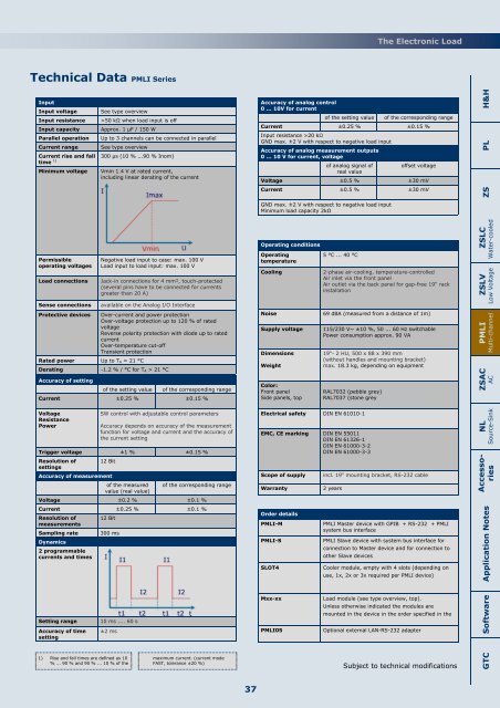
Technical Data PMLI Series<br />
Input<br />
Input voltage<br />
Input resistance<br />
Input capacity<br />
Parallel operation<br />
Current range<br />
Current rise and fall<br />
time 1)<br />
Minimum voltage<br />
Permissible<br />
operating voltages<br />
<strong>Load</strong> connections<br />
Sense connections<br />
See type overview<br />
>50 kΩ when load input is off<br />
Approx. 1 µF / 150 W<br />
Up to 3 channels can be connected in parallel<br />
See type overview<br />
300 µs (10 % ...90 % Inom)<br />
Vmin 1.4 V at rated current,<br />
including linear derating of the current<br />
Negative load input to case: max. 100 V<br />
<strong>Load</strong> input to load input: max. 100 V<br />
Jack-in connections for 4 mm², touch-protected<br />
(several pins have to be connected for currents<br />
greater than 20 A)<br />
available on the Analog I/O Interface<br />
Protective devices Over-current and power protection<br />
Over-voltage protection up to 120 % of rated<br />
voltage<br />
Reverse polarity protection with diode up to rated<br />
current<br />
Over-temperature cut-off<br />
Transient protection<br />
Rated power Up to TA = 21 °C<br />
Derating -1.2 % / °C for TA > 21 °C<br />
Accuracy of setting<br />
of the setting value of the corresponding range<br />
Current ±0.25 % ±0.15 %<br />
Voltage<br />
Resistance<br />
Power<br />
SW control with adjustable control parameters<br />
Accuracy depends on accuracy of the measurement<br />
function for voltage and current and the accuracy of<br />
the current setting<br />
Trigger voltage ±1 % ±0.15 %<br />
Resolution of 12 Bit<br />
settings<br />
Accuracy of measurement<br />
of the measured of the corresponding range<br />
value (real value)<br />
Voltage ±0.2 % ±0.1 %<br />
Current ±0.25 % ±0.1 %<br />
Resolution of 12 Bit<br />
measurements<br />
Sampling rate 300 ms<br />
Dynamics<br />
2 programmable<br />
currents and times<br />
Accuracy of analog control<br />
0 ... 10V for current<br />
of the setting value of the corresponding range<br />
Current ±0.25 % ±0.15 %<br />
Input resistance >20 kΩ<br />
GND max. ±2 V with respect to negative load input<br />
Accuracy of analog measurement outputs<br />
0 ... 10 V for current, voltage<br />
of analog signal of<br />
offset voltage<br />
real value<br />
Voltage ±0.5 % ±30 mV<br />
Current ±0.5 % ±30 mV<br />
GND max. ±2 V with respect to negative load input<br />
Minimum load capacity 2kΩ<br />
Operating conditions<br />
Operating<br />
temperature<br />
Cooling<br />
5 °C ... 40 °C<br />
2-phase air-cooling, temperature-controlled<br />
Air inlet via the front panel<br />
Air outlet via the back panel for gap-free 19“ rack<br />
installation<br />
Noise 69 dBA (measured from a distance of 1m)<br />
Supply voltage<br />
Dimensions<br />
Weight<br />
Color:<br />
Front panel<br />
Side panels, top<br />
115/230 V~ ±10 %, 50 ... 60 Hz switchable<br />
Power consumption approx. 90 VA<br />
19“- 2 HU, 500 x 88 x 390 mm<br />
(without handles and mounting bracket)<br />
max. 18.3 kg, depending on equipment<br />
RAL7032 (pebble grey)<br />
RAL7037 (stone grey<br />
Electrical safety DIN EN 61010-1<br />
EMC, CE marking DIN EN 55011<br />
DIN EN 61326-1<br />
DIN EN 61000-3-2<br />
DIN EN 61000-3-3<br />
Scope of supply<br />
Warranty<br />
Order details<br />
PMLI-M<br />
PMLI-S<br />
SLOT4<br />
incl. 19“ mounting bracket, RS-232 cable<br />
2 years<br />
PMLI Master device with GPIB + RS-232 + PMLI<br />
system bus interface<br />
PMLI Slave device with system bus interface for<br />
connection to Master device and for connection to<br />
other Slave devices<br />
Cooler module, empty with 4 slots (depending on<br />
use, 1x, 2x or 3x required per PMLI device)<br />
Application Notes ZS PL H&H<br />
ZSLC<br />
Water-cooled<br />
ZSLV<br />
Low Voltage<br />
PMLI<br />
Multi-channel<br />
ZSAC<br />
AC<br />
NL<br />
Source-Sink<br />
Accessories<br />
Setting range<br />
Accuracy of time<br />
setting<br />
10 ms .... 60 s<br />
±2 ms<br />
Mxx-xx<br />
PMLI05<br />
<strong>Load</strong> module (see type overview, top).<br />
Unless otherwise indicated the modules are<br />
mounted in the device in the order specified in the<br />
Optional external LAN-RS-232 adapter<br />
Software<br />
1) Rise and fall times are defined as 10<br />
% ... 90 % and 90 % ... 10 % of the<br />
maximum current. (current mode<br />
FAST, tolerance ±20 %)<br />
Subject to technical modifications<br />
GTC<br />
37