The Electronic Load
The Electronic Load
The Electronic Load

Create successful ePaper yourself
Turn your PDF publications into a flip-book with our unique Google optimized e-Paper software.
<strong>The</strong> <strong>Electronic</strong> <strong>Load</strong><br />
<strong>Load</strong>ing AC voltages with a DC load<br />
<strong>Load</strong>ing AC Voltages<br />
<strong>The</strong>re is often a need to load an<br />
alternating voltage.<br />
If there is no specific AC load<br />
you can substitute a DC load<br />
with a rectifier.<br />
Waveform<br />
It is important to note that the<br />
unit under test is loaded with<br />
different waveforms depending<br />
on the chosen operating mode.<br />
Example for Constant<br />
Current Mode<br />
Once, after the zero-crossing of<br />
the alternating voltage, the<br />
input voltage at the load input is<br />
greater than the minimum<br />
voltage of the electronic load,<br />
the current is adjusted to the<br />
preset value and remains<br />
constant for the whole trajectory<br />
of the half wave.<br />
Only when the AC voltage<br />
passes through zero again the<br />
current will drop back to 0.<br />
Example for Constant<br />
Resistance Mode<br />
In resistance mode the<br />
waveform of the load current<br />
depends on the height and<br />
waveform of the input voltage.<br />
This means that the current and<br />
the rectified input voltage are<br />
also half wave-shaped so that<br />
an approximately sinusoidal load<br />
current is produced for the test<br />
unit.<br />
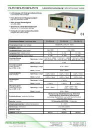
If in direct current mode a<br />
constant current of 1 A is set,<br />
then in the case of rectified<br />
alternating voltage it is also 1 A.<br />
<strong>The</strong> waveform in this case<br />
however is rectangular.<br />
<strong>The</strong> result: A rectangular load<br />
current is applied to the<br />
AC source.<br />
Due to the rectangular<br />
waveform the current display of<br />
the electronic load shows the<br />
effective value of the load<br />
current.<br />
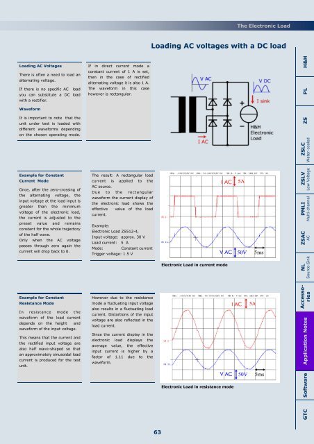
Example:<br />
<strong>Electronic</strong> <strong>Load</strong> ZS512-4,<br />
Input voltage: approx. 30 V<br />
<strong>Load</strong> current: 5 A<br />
Mode: Constant current<br />
Trigger voltage: 1.5 V<br />
However due to the resistance<br />
mode a fluctuating input voltage<br />
also results in a fluctuating load<br />
current. Distortions of the input<br />
voltage are also reflected in the<br />
load current.<br />
Since the current display in the<br />
electronic load displays the<br />
average value, the effective<br />
input current is higher by a<br />
factor of 1.11 due to the<br />
waveform.<br />
<strong>Electronic</strong> <strong>Load</strong> in current mode<br />
Application Notes ZS PL H&H<br />
ZSLC<br />
Water-cooled<br />
ZSLV<br />
Low Voltage<br />
PMLI<br />
Multi-channel<br />
ZSAC<br />
AC<br />
NL<br />
Source-Sink<br />
Accessories<br />
<strong>Electronic</strong> <strong>Load</strong> in resistance mode<br />
GTC<br />
Software<br />
63