The Electronic Load
The Electronic Load
The Electronic Load

You also want an ePaper? Increase the reach of your titles
YUMPU automatically turns print PDFs into web optimized ePapers that Google loves.
<strong>The</strong> <strong>Electronic</strong> <strong>Load</strong><br />
Application Notes ZS PL H&H<br />
ZSLC<br />
Water-cooled<br />
ZSLV<br />
Low Voltage<br />
PMLI<br />
Multi-channel<br />
ZSAC<br />
AC<br />
NL<br />
Source-Sink<br />
Accessories<br />
H&H Application Note #3<br />
Simulation of exponential inrush currents<br />
Function<br />
Via the analog control input of<br />
the ZS electronic load with the<br />
help of a few passive<br />
components a control signal can<br />
be generated which simulates<br />
the current consumption of<br />
devices with exponentially<br />
decaying inrush current peaks.<br />
Applications<br />
Simulation of current<br />
consumption of devices at the<br />
point of switching on, e.g. light<br />
bulbs, engines etc.<br />
Measurement set-up<br />
As stated in the circuit, the<br />
connected input voltage is fed<br />
via an RC network to the<br />
analog control input of the<br />
device.<br />
As soon as the SW1 switch is<br />
closed, at the AIN10+ control<br />
input the RC network<br />
generates a rapid voltage rise<br />
with a subsequent exponential<br />
fall.<br />
<strong>The</strong> peak current is<br />
determined by the value of the<br />
connected voltage and the<br />
resistors R2 and R3.<br />
R1 is used to generate the<br />
continuous current which is set<br />
after the decay of the poweron<br />
process.<br />
<strong>The</strong> current can be calculated<br />
from the voltages at the<br />
voltage divider R1, R2 and R3<br />
and the technical data of the<br />
electronic load.<br />
If using the 10 V control<br />
input the full current of the<br />
selected range flows at 10 V.<br />
<strong>The</strong> decay time constant is<br />
calculated from the resistors R2<br />
and R3 with the capacitor C1.<br />
<strong>The</strong> input resistance of the<br />
analog control input - 20 kOhm<br />
- must also be taken into<br />
account.<br />
<strong>The</strong> device must be set to<br />
constant current operating<br />
mode and external control.<br />
For smaller input voltages the<br />
5 V control input can also be<br />
used in place of the 10 V control<br />
input.<br />
Note<br />
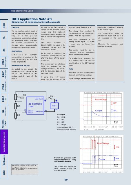
Example:<br />
R1: 10 kΩ<br />
R2: 1 kΩ<br />
R3: 1 kΩ<br />
C1: 100 µF<br />
Input voltage: 12 V<br />
<strong>Electronic</strong> load: ZS3606<br />
Note that the load current value<br />
depends on the input voltage.<br />
Input voltage interferences are<br />
coupled by capacitor C1 directly<br />
to the control signal.<br />
<strong>The</strong> resistances must be<br />
dimensioned such that 10 V is<br />
not exceeded at the control<br />
input.<br />
Otherwise the electronic load<br />
could be damaged.<br />
Software<br />
GTC<br />
H&H offers no guarantee for the function of<br />
the suggested applications.<br />
H&H offers no guarantee for damage resulting<br />
from such applications.<br />
Switch-on process with<br />
electromechanical relay<br />
and contact bounce<br />
<strong>The</strong> current also follows the<br />
input voltage during the<br />
contact bounce.<br />
60