The Electronic Load
The Electronic Load
The Electronic Load

Create successful ePaper yourself
Turn your PDF publications into a flip-book with our unique Google optimized e-Paper software.
<strong>The</strong> <strong>Electronic</strong> <strong>Load</strong><br />
Function<br />
Via the analog control input of<br />
the ZS electronic load a direct<br />
analog adder.<br />
If only one control input is<br />
connected, only this signal is<br />
voltage and an alternating used to set the load current.<br />
voltage from a function<br />
If both control inputs are<br />
generator can overlap the load<br />
connected, the control signals<br />
current with alternating current<br />
are added.<br />
portions.<br />
Applications<br />
Test of dynamic behaviour of<br />
power supplies, simulation of<br />
loads with alternating current<br />
<strong>The</strong> ratio at which the signals<br />
are added is stated by the<br />
ratio of the control voltages<br />
(5 V and 10 V) for the rated<br />
current.<br />
portions.<br />
Connecting two external<br />
Measurement Set-Up<br />
resistors can change the<br />
addition ratio.<br />
<strong>The</strong> ZS electronic loads have<br />
two external control inputs for<br />
the signal levels 0 ... 5 V and<br />
0 ... 10 V.<br />
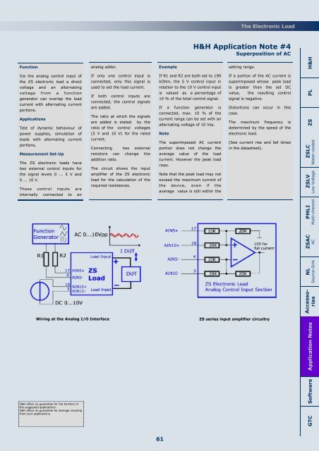
<strong>The</strong> circuit shows the input<br />
amplifier of the ZS electronic<br />
load for the calculation of the<br />
required resistances.<br />
<strong>The</strong>se control inputs are<br />
internally connected to an<br />
Wiring at the Analog I/O Interface<br />
Example<br />
If R1 and R2 are both set to 190<br />
kOhm, the 5 V control input in<br />
relation to the 10 V control input<br />
is valued as a percentage of<br />
10 % of the total control signal.<br />
If a function generator is<br />
connected, max. 10 % of the<br />
current range can be set with an<br />
alternating voltage of 10 Vss.<br />
Note<br />
<strong>The</strong> superimposed AC current<br />
portion does not change the<br />
average value of the load<br />
current. However the peak load<br />
rises.<br />
Note that the peak load may not<br />
exceed the maximum current of<br />
the device, even if the<br />
average value is still within the<br />
H&H Application Note #4<br />
Superposition of AC<br />
setting range.<br />
If a portion of the AC current is<br />
superimposed whose peak load<br />
is greater than the set DC<br />
value, the resulting control<br />
signal is negative.<br />
Distortions can occur in this<br />
case.<br />
<strong>The</strong> maximum frequency is<br />
determined by the speed of the<br />
electronic load.<br />
(See current rise and fall times<br />
in the datasheet).<br />
ZS series input amplifier circuitry<br />
Application Notes ZS PL H&H<br />
ZSLC<br />
Water-cooled<br />
ZSLV<br />
Low Voltage<br />
PMLI<br />
Multi-channel<br />
ZSAC<br />
AC<br />
NL<br />
Source-Sink<br />
Accessories<br />
H&H offers no guarantee for the function of<br />
the suggested applications.<br />
H&H offers no guarantee for damage resulting<br />
from such applications.<br />
Software<br />
GTC<br />
61