H.264 Megapixel Indoor/Outdoor Dome IP Camera User Manual
H.264 Megapixel Indoor/Outdoor Dome IP Camera User Manual
H.264 Megapixel Indoor/Outdoor Dome IP Camera User Manual

Create successful ePaper yourself
Turn your PDF publications into a flip-book with our unique Google optimized e-Paper software.
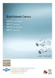
<strong>H.264</strong> <strong>Megapixel</strong><br />
<strong>Indoor</strong>/<strong>Outdoor</strong> <strong>Dome</strong><br />
<strong>IP</strong> <strong>Camera</strong> <strong>User</strong> <strong>Manual</strong><br />
Product: BLK-<strong>IP</strong>D105M<br />
Please read this manual before using your camera, and always follow the instructions for<br />
safety and proper use. Save this manual for future reference.<br />
BLK-<strong>IP</strong>D105M_CM<br />
10/26/11
�<br />
CAUTION<br />
LEGAL NOTICE<br />
ii www.digiop.com<br />
Do not operate this camera in environments where the temperatures or humidity is outside the recommended range.<br />
Doing so my cause electric shock and shorten the life of the product.<br />
DIGIOP products are designed to meet safety and performance standards with the use of specific DIGIOP<br />
authorized accessories. DIGIOP disclaims liability associated with the use of non-DIGIOP authorized accessories.<br />
The recording, transmission, or broadcast of any person’s voice without their consent or a court order is strictly<br />
prohibited by law.<br />
DIGIOP makes no representations concerning the legality of certain product applications such as the making,<br />
transmission, or recording of video and/or audio signals of others without their knowledge and/or consent. We<br />
encourage you to check and comply with all applicable local, state, and federal laws and regulations before<br />
engaging in any form of surveillance or any transmission of radio frequencies.<br />
Other trademarks and trade names may be used in this document to refer to either the entities claiming the marks<br />
and names or their products. DIGIOP, Inc. disclaims any proprietary interest in trademarks and trade names other<br />
than its own.<br />
Microsoft, Windows, and Internet Explorer are either registered trademarks or trademarks of Microsoft Corporation in<br />
the United States and/or other countries. Aptina is a trademark of Aptina Imaging Corporation.<br />
No part of this document may be reproduced or distributed in any form or by any means without the express written<br />
permission of DIGIOP, Inc.<br />
© 2011 DIGIOP, Inc. All Rights Reserved.<br />
3850 Priority Way South Drive, Suite 200, Indianapolis, IN 46240<br />
Sales/Support: 1.877.972.2522
Table of Contents<br />
SECTION 1 Features . . . . . . . . . . . . . . . . . . . . . . . . . . . . . . . . . . . . . . . . . . . . . . . . . . . . . . . . . . . . . . . . . . . . . . . . . . . 2<br />
SECTION 2 Installation and Setup . . . . . . . . . . . . . . . . . . . . . . . . . . . . . . . . . . . . . . . . . . . . . . . . . . . . . . . . . . . . . . . 3<br />
2.1 What’s in the box . . . . . . . . . . . . . . . . . . . . . . . . . . . . . . . . . . . . . . . . . . . . . . . . . . . . . . . . . . . . . . . . . . . .3<br />
2.2 Tools you need . . . . . . . . . . . . . . . . . . . . . . . . . . . . . . . . . . . . . . . . . . . . . . . . . . . . . . . . . . . . . . . . . . . . . . .3<br />
2.3 Mount the camera . . . . . . . . . . . . . . . . . . . . . . . . . . . . . . . . . . . . . . . . . . . . . . . . . . . . . . . . . . . . . . . . . . .3<br />
2.4 Connections . . . . . . . . . . . . . . . . . . . . . . . . . . . . . . . . . . . . . . . . . . . . . . . . . . . . . . . . . . . . . . . . . . . . . . . . .5<br />
2.4.1 Audio in/out connections . . . . . . . . . . . . . . . . . . . . . . . . . . . . . . . . . . . . . . . . . . . . . . . . . . . . . . . . .6<br />
2.4.2 Sensor in (DI) connection . . . . . . . . . . . . . . . . . . . . . . . . . . . . . . . . . . . . . . . . . . . . . . . . . . . . . . . . .7<br />
2.4.3 Alarm out (DO) connection . . . . . . . . . . . . . . . . . . . . . . . . . . . . . . . . . . . . . . . . . . . . . . . . . . . . . . . .8<br />
2.4.4 RS-485 device connection. . . . . . . . . . . . . . . . . . . . . . . . . . . . . . . . . . . . . . . . . . . . . . . . . . . . . . . . .8<br />
2.4.5 LAN and power connections . . . . . . . . . . . . . . . . . . . . . . . . . . . . . . . . . . . . . . . . . . . . . . . . . . . . . . .9<br />
2.5 Install <strong>IP</strong>Admin Tool . . . . . . . . . . . . . . . . . . . . . . . . . . . . . . . . . . . . . . . . . . . . . . . . . . . . . . . . . . . . . . . . .10<br />
2.6 Configure the camera network settings . . . . . . . . . . . . . . . . . . . . . . . . . . . . . . . . . . . . . . . . . . . . . . . . .10<br />
2.6.1 Configuring cameras on networks with DHCP . . . . . . . . . . . . . . . . . . . . . . . . . . . . . . . . . . . . . . .11<br />
2.6.2 Configuring cameras on networks without DHCP . . . . . . . . . . . . . . . . . . . . . . . . . . . . . . . . . . . .13<br />
2.7 Setup the camera Basic Configuration . . . . . . . . . . . . . . . . . . . . . . . . . . . . . . . . . . . . . . . . . . . . . . . . . .17<br />
2.8 Aim, focus, and image quality adjustment . . . . . . . . . . . . . . . . . . . . . . . . . . . . . . . . . . . . . . . . . . . . . .21<br />
2.8.1 Aim . . . . . . . . . . . . . . . . . . . . . . . . . . . . . . . . . . . . . . . . . . . . . . . . . . . . . . . . . . . . . . . . . . . . . . . . . .21<br />
2.8.2 Focus . . . . . . . . . . . . . . . . . . . . . . . . . . . . . . . . . . . . . . . . . . . . . . . . . . . . . . . . . . . . . . . . . . . . . . . . .21<br />
2.8.3 Image quality adjustments. . . . . . . . . . . . . . . . . . . . . . . . . . . . . . . . . . . . . . . . . . . . . . . . . . . . . . .22<br />
2.9 Speaker/microphone setup . . . . . . . . . . . . . . . . . . . . . . . . . . . . . . . . . . . . . . . . . . . . . . . . . . . . . . . . . . .22<br />
2.10 Cleaning . . . . . . . . . . . . . . . . . . . . . . . . . . . . . . . . . . . . . . . . . . . . . . . . . . . . . . . . . . . . . . . . . . . . . . . . . . .24<br />
SECTION 3 Specifications . . . . . . . . . . . . . . . . . . . . . . . . . . . . . . . . . . . . . . . . . . . . . . . . . . . . . . . . . . . . . . . . . . . . . 25<br />
APPENDIX A Troubleshooting . . . . . . . . . . . . . . . . . . . . . . . . . . . . . . . . . . . . . . . . . . . . . . . . . . . . . . . . . . . . . . . . . . . 28<br />
A.1 Reboot camera . . . . . . . . . . . . . . . . . . . . . . . . . . . . . . . . . . . . . . . . . . . . . . . . . . . . . . . . . . . . . . . . . . . . .28<br />
A.2 Set camera to factory default network settings . . . . . . . . . . . . . . . . . . . . . . . . . . . . . . . . . . . . . . . . . .28<br />
A.3 Checking your Firmware . . . . . . . . . . . . . . . . . . . . . . . . . . . . . . . . . . . . . . . . . . . . . . . . . . . . . . . . . . . . .29<br />
A.4 Support . . . . . . . . . . . . . . . . . . . . . . . . . . . . . . . . . . . . . . . . . . . . . . . . . . . . . . . . . . . . . . . . . . . . . . . . . . .29<br />
APPENDIX B Dimensions . . . . . . . . . . . . . . . . . . . . . . . . . . . . . . . . . . . . . . . . . . . . . . . . . . . . . . . . . . . . . . . . . . . . . . . 30<br />
APPENDIX C Power over Ethernet . . . . . . . . . . . . . . . . . . . . . . . . . . . . . . . . . . . . . . . . . . . . . . . . . . . . . . . . . . . . . . . . 32<br />
C.1 PoE compatibility . . . . . . . . . . . . . . . . . . . . . . . . . . . . . . . . . . . . . . . . . . . . . . . . . . . . . . . . . . . . . . . . . . .32<br />
C.2 Power classification . . . . . . . . . . . . . . . . . . . . . . . . . . . . . . . . . . . . . . . . . . . . . . . . . . . . . . . . . . . . . . . . .32<br />
<strong>H.264</strong> <strong>Megapixel</strong> <strong>Indoor</strong>/<strong>Outdoor</strong> <strong>Dome</strong> <strong>IP</strong> <strong>Camera</strong><br />
1
SECTION 1<br />
Features<br />
SECTION 1: FEATURES<br />
The DIGIOP Black BLK-<strong>IP</strong>D105M is a professional, premium-grade dome camera designed for outdoor or indoor installation. It<br />
features:<br />
• Fixed vandal-proof dome<br />
• Gimbal mounted camera<br />
• Aptina (Micron) 1/3.2” (4:3) CMOS 2 <strong>Megapixel</strong> sensor<br />
• Digital day/night<br />
• Dual streaming mode<br />
• De-interlacing on DSP<br />
• Supports burnt-in text, unicast/multicast<br />
• Video compression: <strong>H.264</strong>/MPEG/MJPEG, 30FPS@D1<br />
• Audio compression: G.711 (µLaw, aLaw)/PCM<br />
• Supports motion detection, 2-way mono audio support<br />
• Supports 10/100 Base-T Ethernet, RTSP/ HTTP protocol support<br />
• RS485 support<br />
• Micro SD card support<br />
• PoE support<br />
• OSD support<br />
• Software development kit (SDK) available<br />
• Built-in Video Content Analysis features<br />
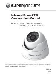
Power<br />
adapter<br />
connector<br />
LAN connector<br />
2 www.digiop.com<br />
Micro SD<br />
card slot<br />
BLK-<strong>IP</strong>D105M camera without the dome cover<br />
LAN/power<br />
extension cable<br />
socket<br />
Reset<br />
button<br />
Terminal block<br />
connector
SECTION 2<br />
Installation and Setup<br />
2.1 What’s in the box<br />
Your dome camera includes the following:<br />
• BLK-<strong>IP</strong>D105M camera<br />
• DC power adapter with power plugs for different powering sources<br />
• Base seal (surface cushion)<br />
• Power extension cable<br />
• 11-pin terminal block<br />
• Hardware installation kit with a hex wrench, 3 screws and wall inserts<br />
• CD mini disk with application software and documentation<br />
2.2 Tools you need<br />
To install the camera, you will need:<br />
• Phillips #2 screwdriver<br />
• PC with Microsoft ® Windows ® XP with SP3 or newer, 32- or 64-bit system<br />
Depending on how the camera is mounted, you may also need:<br />
• Hammer<br />
• Drill with bits for drilling mounting holes<br />
• 1-3/8” hole saw<br />
2.3 Mount the camera<br />
SECTION 2: INSTALLATION AND SETUP<br />
1. Determine where the camera will be mounted and record the Media Access Control (MAC) address of the camera. The MAC<br />
address can be found on the label on the base of the camera. Record the information in the following table.<br />
Location:<br />
MAC address:<br />
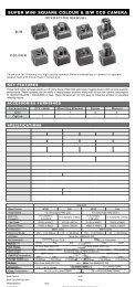
2. Separate the camera dome from the camera base housing by loosening the three captive screws with the hex wrench<br />
provided.<br />
<strong>H.264</strong> <strong>Megapixel</strong> <strong>Indoor</strong>/<strong>Outdoor</strong> <strong>Dome</strong> <strong>IP</strong> <strong>Camera</strong><br />
3
SECTION 2: INSTALLATION AND SETUP<br />
4 www.digiop.com<br />
<strong>Camera</strong> dome removal<br />
3. Using the base as a template, mark the location of the three mounting screw holes.<br />
4. Drill mounting screw holes into the mounting surface:<br />
— If the mounting surface is a soft material, such as a drywall, drill and install drywall inserts for the mounting screws.<br />
OR<br />
— If the mounting surface is a very soft material, such as ceiling tile, place a wood block behind the tile and drill holes for<br />
mounting screws long enough to secure the base to the block.<br />
OR<br />
— If mounting the camera on a hard surface, such as wood, drill the mounting screw holes into the surface before<br />
attaching the camera.<br />
5. Determine the extension cable routing. If the cable is to be routed through the hole in the bottom of the base, perform the<br />
following steps. If the cable will be routed through the conduit port in the side of the base and routed to a nearby junction<br />
box, skip to step 9.<br />
6. While holding the camera in its mounting position, align the mounting screw holes in the base with the holes drilled for the<br />
mounting screws. Mark the location of hole for the extension cable routing.<br />
7. Drill a 1-3/8” hole through the mounting surface for the extension cable.<br />
8. If you are routing interface cables through conduit attached to the bottom of the base, do the following:
SECTION 2: INSTALLATION AND SETUP<br />
a. Unplug the extension cable from the camera electronics and remove it from the camera.<br />
b. Install a conduit fitting onto the bottom of the base.<br />
c. Install a junction box close enough to the camera for the extension cable LAN and power connectors to be in the box.<br />
Attach the conduit for the junction box to the conduit fitting on the bottom of the camera base.<br />
9. Place the base seal over the base, aligning the holes for the mounting screws. Attach the camera and seal to the surface with<br />
three screws. Skip to step 15.<br />
10. Unplug the extension cable from the camera electronics and remove it from the camera.<br />
11. Remove the conduit port plug on the side of the base and install it in the cable port in the bottom of the base.<br />
12. Install a conduit fitting onto the side of the base.<br />
13. Place the base seal over the base, aligning the holes for the mounting screws in the base with those in the seal. Attach the<br />
base and seal to the mounting surface with three screws.<br />
14. Install a junction box with conduit close enough to the camera for the extension cable LAN and power connectors to be in<br />
the box. When installing the junction box, attach the conduit to the fitting on the side of the camera base.<br />
15. Route the extension cable Molex ® connector end into the camera and re-attach it to the electronics.<br />
16. Remove the protective cover on the camera lens.<br />
2.4 Connections<br />
Connections to the camera for audio in and out (microphone and speaker), D/I sensor, alarm, and RS-485 control are made through<br />
the 11-pin terminal block.<br />
11-pin terminal block<br />
<strong>H.264</strong> <strong>Megapixel</strong> <strong>Indoor</strong>/<strong>Outdoor</strong> <strong>Dome</strong> <strong>IP</strong> <strong>Camera</strong><br />
5
SECTION 2: INSTALLATION AND SETUP<br />
6 www.digiop.com<br />
Terminal block pin assignments<br />
NOTE The terminal connections do not support analog video output.<br />
NOTE: When connecting leads from external devices<br />
to the terminal block, use the pin definitions shown on<br />
the circuit board as a guide. Pin definitions on the circuit<br />
board may be different from those shown below.<br />
The 11-pin terminal block may be detached from the camera. Install the block in the location shown above.<br />
2.4.1 Audio in/out connections<br />
The camera includes an interface for a mono audio input (from a microphone) and a mono audio output (to a speaker). The audio<br />
output is a low level signal that requires an amplified speaker (see Specifications). The configuration of the audio wiring (Aout, Ain)<br />
is shown in the diagram below.<br />
To connect a speaker and/or microphone to the camera:<br />
Audio in/out wiring schematic<br />
1. Route speaker and/or microphone wiring through the cable channel and into the camera base housing.<br />
2. Strip 1/4” of insulation from the wires and insert them into the terminal block in the locations shown connector terminal<br />
figure above. The common (ground) leads to the microphone and speaker share the same terminal block pin.
2.4.2 Sensor in (DI) connection<br />
SECTION 2: INSTALLATION AND SETUP<br />
The camera provides one channel for sensor input that can be connected to either a voltage type or relay type sensor. For voltage<br />
type sensors, the camera allows a maximum input of 24 V DC, with a 1 V DC threshold (see Specifications). The configuration of the<br />
sensor input wiring is illustrated in the diagrams below.<br />
CAUTION<br />
�<br />
To connect a sensor to the camera:<br />
Do not exceed the maximum input voltage or the relay switching rate. Refer to the specifications in this<br />
manual for more information.<br />
Voltage type sensor wiring schematic<br />
Relay type sensor wiring schematic<br />
1. Route sensor wiring through the cable channel and into the camera base housing.<br />
2. Strip 1/4” of insulation from the sensor wires and insert them into the terminal block in the DI pin locations shown above.<br />
The pin marked “C” in the terminal block is the common (COM) pin.<br />
<strong>H.264</strong> <strong>Megapixel</strong> <strong>Indoor</strong>/<strong>Outdoor</strong> <strong>Dome</strong> <strong>IP</strong> <strong>Camera</strong><br />
7
SECTION 2: INSTALLATION AND SETUP<br />
2.4.3 Alarm out (DO) connection<br />
The camera supports one alarm out connection to relay type device. It provides up to 24 V AC @ 500 mA or 12 V DC @ 1 A. The<br />
configuration of the relay type alarm wiring is illustrated in the diagram below.<br />
CAUTION<br />
� Do not exceed the maximum relay rating. Refer to the specifications in this manual for more information.<br />
To connect an alarm reporting device to the camera:<br />
8 www.digiop.com<br />
Relay type alarm wiring schematic<br />
1. Route alarm out wiring through the cable channel and into the camera base housing.<br />
2. Strip 1/4” of insulation from the wires and insert them into the terminal block in the DO pin locations shown above. The pin<br />
marked “C” in the terminal block is the common (COM) pin.<br />
2.4.4 RS-485 device connection<br />
The camera provides one RS-485 interface connection. The wiring signal polarity to the terminal block is shown in the schematic<br />
below.<br />
RS-485 device wiring schematic
To connect an RS-485 device wiring to the camera:<br />
SECTION 2: INSTALLATION AND SETUP<br />
1. Route RS-485 device wiring through the cable channel and into the camera base housing.<br />
2. Strip 1/4” of insulation from the wires and insert them into the terminal block. Observe the signal polarity shown in the<br />
schematic.<br />
2.4.5 LAN and power connections<br />
1. Route a LAN drop cable into the camera and plug it into the RJ-45 LAN connector.<br />
Power<br />
connector<br />
LAN<br />
connector<br />
2. Route the wire end of the power extension cable into the camera and connect it to the 12 VDC power connector. If the<br />
camera is powered through the LAN cable, DO NOT apply power to the camera at this time.<br />
3. Connect the other end of the power extension cable to the DC12V power adapter. The polarity of the adapter connector is<br />
shown in the following diagram. DO NOT apply power to the camera at this time.<br />
�<br />
CAUTION<br />
When applying power to the camera, ensure that the polarity is correct. An incorrect connection may cause a malfunction and<br />
can damage the camera.<br />
<strong>H.264</strong> <strong>Megapixel</strong> <strong>Indoor</strong>/<strong>Outdoor</strong> <strong>Dome</strong> <strong>IP</strong> <strong>Camera</strong><br />
9
SECTION 2: INSTALLATION AND SETUP<br />
2.5 Install <strong>IP</strong>Admin Tool<br />
The <strong>IP</strong>Admin Tool, included on the CD mini disk, is a utility that will discover cameras installed on your network and enable you<br />
to perform the initial network setup for each camera. After a camera is setup on the network, the Microsoft Internet Explorer ®<br />
web browser can be used to see video from the camera, set the camera’s password, date and time, finalize camera hardware<br />
adjustments, and configure the camera for functional requirements.<br />
The <strong>IP</strong>AdminTool can be loaded on a Microsoft Windows XP, Vista or Windows 7 operating system (32- or 64-bit). To use this utility<br />
for the initial setup of your camera, your computer must be connected to the same network subnet as your camera.<br />
At a computer on the same LAN (subnet) where your cameras will be installed, do the following:<br />
1. Insert the CD mini disk provided with your camera into your computer’s CD ROM drive and open the CD in a Windows<br />
Explorer window.<br />
2. Find the <strong>IP</strong>AdminTool directory on the CD.<br />
3. Copy the <strong>IP</strong>AdminTool directory with its contents to your computer hard drive.<br />
2.6 Configure the camera network settings<br />
Devices attached to a Local Area Network (LAN) are each assigned a unique address (<strong>IP</strong> address) that they use when sending<br />
messages with each other. No two devices on a single Ethernet network can have the same <strong>IP</strong> address. Otherwise, addressing<br />
conflicts will occur.<br />
When your <strong>IP</strong> camera is attached to a network and initially powered on, it attempts acquire compatible network settings from<br />
a DHCP server. If it cannot find a DHCP server, it configures itself with the following static <strong>IP</strong> address, subnet mask, and gateway<br />
setting, which may or may not be compatible with other devices on the network.<br />
<strong>IP</strong> address: 192.168.0.100<br />
Subnet mask: 255.255.255.0<br />
Gateway: 192.168.0.1<br />
Whether it acquires a dynamic (changeable) <strong>IP</strong> address and other network settings from a DHCP server, or uses the default static<br />
(fixed, unchanging) settings, your camera must be configured with static network settings that are compatible with the network<br />
configuration. Additionally, if DHCP is not used on your network, DIGIOP Black cameras must be installed on the network and<br />
configured with new network settings one at a time to avoid addressing conflicts.<br />
Use the following procedure to setup and apply compatible, static, network settings for your camera. If connecting your camera to a<br />
large enterprise network, consult with your network administrator for network settings before attaching the camera to the LAN to<br />
10 www.digiop.com
SECTION 2: INSTALLATION AND SETUP<br />
ensure that your camera won’t conflict with other devices. Your network administrator should also setup WAN (Internet) access to<br />
the camera, if that is needed.<br />
If you encounter a problem and need to contact Technical Support, first complete the chart in Table 1 about your computer (PC) and<br />
camera network settings, if possible. Support will need this information to provide assistance.<br />
2.6.1 Configuring cameras on networks with DHCP<br />
In networks with a DHCP server, the <strong>IP</strong> camera will acquire dynamic (changeable) network settings when it is initially powered on.<br />
These dynamic settings can easily be converted to static settings, or changed to other static settings that are also compatible with<br />
your network.<br />
1. Connect your camera to the LAN, then power on the camera.<br />
2. Open the <strong>IP</strong>AdminTool directory on your computer, then double click the file <strong>IP</strong>AdminTool.exe to start the application.<br />
When the <strong>IP</strong>Admin Tool starts, it will discover all the <strong>IP</strong> devices it supports that exist on the network. The discovery process<br />
may take a few minutes.<br />
Check the list of <strong>IP</strong> devices found by <strong>IP</strong>Admin Tool. You can identify your camera by the MAC address. If the camera was not<br />
found, click the Refresh button every minute until your camera appears in the list.<br />
3. In the <strong>IP</strong>Admin Tool device list, use the camera’s MAC Address to find the camera you are installing. After finding the camera,<br />
right click the entry, then select <strong>IP</strong> Address from the drop-down list. An <strong>IP</strong> Setup window will open.<br />
<strong>H.264</strong> <strong>Megapixel</strong> <strong>Indoor</strong>/<strong>Outdoor</strong> <strong>Dome</strong> <strong>IP</strong> <strong>Camera</strong><br />
11
SECTION 2: INSTALLATION AND SETUP<br />
4. In the <strong>IP</strong> Setup window, click the Static option bullet to select this option.<br />
Static<br />
Option<br />
If you have other compatible, network settings you want to apply to the device, enter them in the appropriate locations. Click<br />
Setup to save settings.<br />
5. In the Login window, enter the ID and PW (password) for your camera and click Login. The default administrator values for<br />
the ID and PW are root and pass. After entering ID and PW, the <strong>IP</strong> Setup window closes.<br />
6. In the <strong>IP</strong>Admin Tool window, click Refresh and verify that the entry representing the camera now shows the new <strong>IP</strong> address.<br />
7. Continue with procedure 2.7 Setup camera Basic Configuration.<br />
12 www.digiop.com
SECTION 2: INSTALLATION AND SETUP<br />
2.6.2 Configuring cameras on networks without DHCP<br />
NOTE The following procedure works with most networks. For further assistance, contact Technical Support.<br />
<strong>Camera</strong>s installed on a network without a DHCP server will initially use the factory default static network settings:<br />
<strong>IP</strong> address: 192.168.0.100<br />
Subnet mask: 255.255.255.0<br />
Gateway: 192.168.0.1<br />
In networks without a DHCP server, cameras must be powered on and reconfigured one at a time to avoid addressing conflicts<br />
between other cameras, or possibly with another device on the network. Configuring the network settings of your cameras includes<br />
these steps:<br />
— Determine the network settings of your computer.<br />
— Check the network for compatibility with the default static network settings of your camera.<br />
— Find network settings (<strong>IP</strong> addresses) that are not in use and can be assigned to your camera.<br />
— Attach your camera to the network, power it on, and configuring it with new network settings.<br />
Determine the network settings of your computer<br />
1. At a PC attached to the same LAN that will be shared with your camera, determine the <strong>IP</strong> address, subnet mask, and default<br />
gateway of your PC and record it in Table 1. To find this information, do the following at the Windows desktop:<br />
a. Hold down the Windows key and press r to open the Run dialog box.<br />
b. Type cmd in the entry field, then click OK to open the DOS command window.<br />
c. At the command prompt, enter ipconfig. The response will show the your PC’s network settings.<br />
<strong>H.264</strong> <strong>Megapixel</strong> <strong>Indoor</strong>/<strong>Outdoor</strong> <strong>Dome</strong> <strong>IP</strong> <strong>Camera</strong><br />
13
SECTION 2: INSTALLATION AND SETUP<br />
14 www.digiop.com<br />
Example: Typical use of ipconfig in Windows XP<br />
d. Enter the <strong>IP</strong> Address, Subnet Mask, and Default Gateway for your PC’s Ethernet adapter into Table 1.<br />
NOTE<br />
The Ethernet adapter data you see by using ipconfig will probably be different from that shown in the example above. If<br />
you are using Windows Vista or Windows 7, the <strong>IP</strong> address is identified as the “<strong>IP</strong>v4 Address.”<br />
Table 1. PC/<strong>Camera</strong> network settings<br />
<strong>IP</strong> Address<br />
Subnet Mask<br />
Default Gateway<br />
CAUTION<br />
�<br />
Computer (PC) <strong>Camera</strong><br />
If connecting your camera to an enterprise network, consult with your network administrator for the<br />
camera <strong>IP</strong> address, subnet mask, and default gateway.<br />
Find network settings (<strong>IP</strong> addresses) that are not in use<br />
1. At your PC, find an <strong>IP</strong> address on your network that is not in use:<br />
a. Write down the EXACT <strong>IP</strong> address of your PC up to the third/last period. Using the example shown above, this<br />
expression is: 192.168.1.<br />
b. After the third period, include any number between 1 and 254 that is different from the one in your PC’s <strong>IP</strong> address,<br />
168. As a first try, let’s choose 200, which will form the <strong>IP</strong> address 192.168.1.200.
SECTION 2: INSTALLATION AND SETUP<br />
c. Next, use the ping command in the DOS window to see if this <strong>IP</strong> address is in use on your network. The format of the<br />
ping command is:<br />
ping <br />
To test this <strong>IP</strong> address, enter ping 192.168.1.200. Any reply received from the ping indicates that a device on the<br />
network is already using this <strong>IP</strong> address and you can connect to it.<br />
In the example shown above, the message “Reply from 192.168.1.200: ..” indicates that your PC can reach the<br />
device with that <strong>IP</strong> address, and that address is in use (i.e., you cannot use it for your camera).<br />
d. Since the ping test of the <strong>IP</strong> address we tried showed the address was in use, try another number between 1 and 254.<br />
For example, let’s ping 192.168.1.201. At the DOS prompt, enter: ping 192.168.1.201<br />
e. In this test, the message “Request timed out” indicates that your PC cannot reach the device with that <strong>IP</strong> address, and<br />
that address is probably not in use. Enter this number into Table 1. If this test indicated that this <strong>IP</strong> address is in use, try<br />
other <strong>IP</strong> addresses using the steps above until an unused address is found.<br />
Check LAN for default <strong>IP</strong> address compatibility<br />
Because all DIGIOP Black cameras and encoders are factory configured with the static <strong>IP</strong> address 192.168.0.100, check the LAN<br />
before connecting your camera to ensure that network conflicts won’t occur.<br />
<strong>H.264</strong> <strong>Megapixel</strong> <strong>Indoor</strong>/<strong>Outdoor</strong> <strong>Dome</strong> <strong>IP</strong> <strong>Camera</strong><br />
15
16<br />
SECTION 2: INSTALLATION AND SETUP<br />
At a Microsoft Windows computer attached to the LAN subnet where the camera will be connected, open a Command Prompt<br />
window and enter:<br />
ping 192.168.0.100<br />
The “Request timed out” response indicates that the <strong>IP</strong> address is not in use and the camera can be connected without causing<br />
errors.<br />
Attach your camera to the network and power it on<br />
Apply power to the camera. When the camera powers on, it performs an internal initialization, then establishes a connection to the<br />
LAN. Wait until the initialization process completes before continuing. It may take up to 3 minutes for your camera to initialize.<br />
Configure the camera <strong>IP</strong> address<br />
1. Open the <strong>IP</strong>AdminTool directory on your computer, then double click the file <strong>IP</strong>AdminTool.exe to start the application.<br />
When the <strong>IP</strong>Admin Tool starts, it will discover all the <strong>IP</strong> devices it supports that exist on the network. The discovery process<br />
may take a few minutes.<br />
2. In the Product list, find the entry with the same MAC address as the camera you installed. If the camera is not shown, click<br />
Refresh once a minute to update the list.<br />
www.digiop.com
3. Right click on the entry for your camera and select <strong>IP</strong> Address.<br />
4. In the <strong>IP</strong> Setup window:<br />
SECTION 2: INSTALLATION AND SETUP<br />
<strong>IP</strong> Setup window<br />
a. Select the Static option if it is not selected. This option is required if video from the camera will be recorded by a<br />
network DVR, or if you want to view video from the camera across a WAN (Internet).<br />
b. Enter the <strong>IP</strong> address for your camera from Table 1 into the <strong>IP</strong> Address field.<br />
c. Enter the subnet mask for your computer from Table 1 into the Subnet Mask field.<br />
d. Click SETUP. A Login window will open.<br />
5. In the Login window, enter the ID and PW (password) for your camera, then click Login. The default administrator ID and<br />
PW are root and pass. After entering the ID and PW, the <strong>IP</strong> Setup window closes.<br />
6. In the <strong>IP</strong>Admin Tool window, click Refresh and verify that the entry representing the camera now shows the new <strong>IP</strong> address.<br />
7. In the <strong>IP</strong>Admin Tool window, click Refresh and verify that the entry for your camera now shows the new <strong>IP</strong> address.<br />
2.7 Setup the camera Basic Configuration<br />
IIn this procedure, use the Internet Explorer (IE) browser to setup the camera administrator and user passwords, date, and time.<br />
<strong>H.264</strong> <strong>Megapixel</strong> <strong>Indoor</strong>/<strong>Outdoor</strong> <strong>Dome</strong> <strong>IP</strong> <strong>Camera</strong><br />
17
SECTION 2: INSTALLATION AND SETUP<br />
1. Open the IE browser.<br />
2. In the URL field (Internet address), enter the <strong>IP</strong> address for your camera in the format:<br />
http:///<br />
where is the <strong>IP</strong> address of your camera. Following the example earlier in this guide, the entry would be:<br />
http://192.168.1.201<br />
3. If prompted to install an ActiveX control such as AxAll.cab (publisher Cap Co), follow screen prompts to install the software.<br />
NOTE<br />
18 www.digiop.com<br />
IE prompt to install ActiveX control<br />
To load these ActiveX controls, you may need to adjust the security settings of your browser to accept add-ins from<br />
unknown publishers.<br />
Typical initial camera view
NOTE<br />
SECTION 2: INSTALLATION AND SETUP<br />
If, after logging into your camera, you cannot see live video and the message:<br />
“Can not Create XMLDOMDocument Install MSXML4.0” appears, download and install the MS XML 4.0 library. This library can<br />
be found at:<br />
http://www.microsoft.com/downloads/details.aspx?familyid=3144B72B-B4F2-46DA-B4B6-C5D7485F2B42&displaylang=en<br />
4. In the camera window, click the SETUP link in the upper right corner of the window. Enter the <strong>User</strong> name and Password for<br />
the camera, and click OK. The default administrator values are root and pass. The Basic Configuration window will open.<br />
5. In the Basic Configuration menu, click Date & Time.<br />
In the Date & Time Setting options:<br />
a. Select the Time Zone you prefer.<br />
b. Select the synchronization method, or Set <strong>Manual</strong>ly bullet and enter the appropriate information.<br />
<strong>H.264</strong> <strong>Megapixel</strong> <strong>Indoor</strong>/<strong>Outdoor</strong> <strong>Dome</strong> <strong>IP</strong> <strong>Camera</strong><br />
19
SECTION 2: INSTALLATION AND SETUP<br />
c. Select the Sync Source and Interval you prefer.<br />
d. Click Apply.<br />
6. In the Basic Configuration menu, click <strong>User</strong>s.<br />
7. In the <strong>User</strong> List, click root, and then click Modify and follow the prompts. Setup the administrator user with a new<br />
password and click OK.<br />
8. In the <strong>User</strong>s menu, click Apply, then click OK to restart the webserver (if you wish to do so at this time).<br />
9. Click Add to include other administrators, operators or viewers to the user list. Follow the screen prompts to complete the<br />
entries.<br />
10. Click VIEW in the upper right corner of the window to return to the camera live view.<br />
20 www.digiop.com
SECTION 2: INSTALLATION AND SETUP<br />
2.8 Aim, focus, and image quality adjustment<br />
2.8.1 Aim<br />
The camera mount allows the camera to be rotated on three axis to set the horizon alignment, horizontal direction, and up/down<br />
position of the video frame.<br />
Horizon alignment<br />
Lens shroud<br />
Horizontal direction<br />
1. Gently lift the lens shroud off the camera assembly to remove it from the camera assembly.<br />
Up/down position<br />
2. While observing video from the camera, set the horizon alignment by rotating camera module bracket on its horizontal axis<br />
(direction the lens is pointed).<br />
3. Set the horizontal direction of the video frame by rotating camera assembly on its vertical axis.<br />
4. Set the up-down position of the video frame by point the lens up or down.<br />
5. If necessary, make additional adjustments to these settings to perfect the frame of the video.<br />
6. Reinstall the lens shroud<br />
7. Reinstall the camera dome.<br />
2.8.2 Focus<br />
The lens focus and iris is set at the factory and requires no further adjustment.<br />
�<br />
CAUTION<br />
If a camera with a high zoom lens is subjected to a temperature variation of about 18˚F or more, a change of focus may<br />
occur. Make sure to consider the environment when installing a camera with a high zoom lens.<br />
<strong>H.264</strong> <strong>Megapixel</strong> <strong>Indoor</strong>/<strong>Outdoor</strong> <strong>Dome</strong> <strong>IP</strong> <strong>Camera</strong><br />
21
SECTION 2: INSTALLATION AND SETUP<br />
2.8.3 Image quality adjustments<br />
Adjustments to the image brightness, contrast, hue, saturation, and sharpness are performed through the web browser:<br />
1. From the VIEW window, click: SETUP > Video & Audio > Video-In<br />
2. Scroll to the bottom of the screen and click the PREVIEW button. Follow the screen instructions to open the camera view in<br />
another IE window.<br />
3. While observing the video in the PREVIEW window, adjust the values for brightness, contrast, hue, saturation, sharpness,<br />
and/or other parameters on screen. Click Apply to see the effect of the change. Make any necessary adjustments to produce<br />
the best video image.<br />
4. Close the PREVIEW window and click VIEW to return to the normal viewing window.<br />
2.9 Speaker/microphone setup<br />
Verify the functionality of the speaker and microphone setup at the camera, and adjust volume levels.<br />
1. Re-install the camera housing.<br />
22 www.digiop.com
2. On the VIEW screen, click: SETUP > Video & Audio > Audio<br />
to open the Bi-directional Audio Settings menu.<br />
SECTION 2: INSTALLATION AND SETUP<br />
3. In the Bi-directional Audio Settings menu, click the checkboxes to select “Listen to the audio from server with setting<br />
below” and “Talk to the speakers of server”.<br />
4. Click Apply, and then click VIEW to return to the camera view screen.<br />
5. On the VIEW screen, check the SPK and MIC options to enable the speaker at the camera and the microphone on your<br />
computer.<br />
6. At your computer, listen for sounds from the microphone at the camera. If necessary, adjust the volume level in the camera.<br />
Click: SETUP > Video & Audio > Audio<br />
to re-open the Bi-directional Audio Settings menu. In the Listen frame, adjust the volume to the preferred level. Click Apply.<br />
7. Use a microphone at your PC to send audio to the speaker at the camera. Verify that your microphone audio is heard at the<br />
speaker.<br />
To adjust the speaker volume go to the Bi-directional Audio Settings menu. In the Talk to frame, adjust the volume to an<br />
appropriate level. Click Apply.<br />
<strong>H.264</strong> <strong>Megapixel</strong> <strong>Indoor</strong>/<strong>Outdoor</strong> <strong>Dome</strong> <strong>IP</strong> <strong>Camera</strong><br />
23
SECTION 2: INSTALLATION AND SETUP<br />
2.10 Cleaning<br />
Clean the camera housing with an approved glass cleaning solution and a lint free cloth.<br />
• Dust can be removed from the unit by wiping it with a soft damp cloth. To remove stains, gently rub the surface with a soft<br />
cloth moistened with a mild detergent solution, then rinse and dry it with a soft cloth.<br />
• Remove all foreign particles, such as plastic or rubber materials, attached to the camera housing. These may cause damage<br />
to the surface over time.<br />
�<br />
CAUTION<br />
24 www.digiop.com<br />
Do not use benzene, thinner or other chemical products on the camera assembly; these may dissolve the paint and<br />
promote damage of the surfaces. Before using any chemical product, read the accompanying instructions carefully.
SECTION 3<br />
Specifications<br />
Table 2. Specifications<br />
<strong>Camera</strong> Module<br />
CMOS<br />
ELECTRICAL<br />
Image Sensor Aptina (Micron) 1/3.2” (4:3) CMOS 2 <strong>Megapixel</strong><br />
Effective Pixels 1600 x 1200 (UXGA, 2M)<br />
Scanning system Progressive<br />
Resolution 550 TV lines<br />
SNR 71 dB<br />
Min. Illumination 0.5 Lux (50IRE), 0.1 Lux (DSS x5 ON)<br />
Wide Dynamic Range 52 dB (x128)<br />
Color ON/AUTO<br />
AGC Control AUTO<br />
White Balance AUTO<br />
Electronic Shutter Speed AUTO<br />
Lens 3.3~12 mm, F1.6~3.2, <strong>Manual</strong> Iris Lens, CS mount<br />
Day & Night Software Day & Night<br />
Electrical characteristics<br />
Video Output Not available<br />
Audio Input Linein, 1.43 Vp-p (Min 1.35 Vp-p, max 1.49 Vp-p), 39 KΩ<br />
Audio Output Lineout, 46 mW Power, 16 Ω<br />
Sensor(D/I) TTL level 4.5V threshold, Max 50 mA<br />
Alarm(D/O) Max 500 mA@24 VAC or 1A @ 12 VDC<br />
Power Source (Approx) 12 VDC or PoE IEEE 802.3af (Class 0)<br />
Power Consumption (Approx) 2.76W (12 VDC) / 3.6W (PoE)<br />
Video<br />
Compression Format <strong>H.264</strong>, MPEG–4 (up to D1 only), and MJPEG<br />
Number of Streams Dual Stream, configurable<br />
SECTION 3: SPECIFICATIONS<br />
<strong>H.264</strong> <strong>Megapixel</strong> <strong>Indoor</strong>/<strong>Outdoor</strong> <strong>Dome</strong> <strong>IP</strong> <strong>Camera</strong><br />
25
Resolution<br />
(Compression FPS.<br />
NOTE: FPS may be<br />
decreased if using<br />
burnt-in text or VCA.)<br />
SECTION 3: SPECIFICATIONS<br />
<strong>H.264</strong><br />
26 www.digiop.com<br />
5 fps @ UXGA (1600 x 1200)<br />
8 fps @ SXGA (1280 x 1024)<br />
12 fps @ HD720 (1280 x 720)<br />
15 fps @ XGA (1024 x 768), D1 (720 x 480)<br />
MJPEG 15 fps @ UXGA (1600 x 1200)<br />
MPEG–4 15 fps @ D1 (720 x 480)<br />
Motion Detection Supported<br />
Burnt-in Text (Digital) Supported (DSP)<br />
Output Not supported<br />
Audio<br />
Input/output 1/1 channel<br />
Compression Format G.711<br />
Function<br />
Digital Input/output 1/1 channel<br />
RS-485 Supported<br />
Network 10/100Base-T<br />
Power over Ethernet Supported<br />
Protocol<br />
TCP/<strong>IP</strong>, UDP/<strong>IP</strong>, HTTP, RTSP, RTCP, RTP/UDP, RTP/TCP, SNTP, mDNS, UPnP, SMTP, SOCK, IGMP, DHCP, FTP,<br />
DDNS, SSL v2/v3, IEEE 802.1X, SSH, SNMP v2/v3<br />
SD Slot Supported — MicroSD (MicroSD card not included)<br />
Mechanical characteristics<br />
Material Aluminum (die cast) / polycarbonate<br />
Color Ivory<br />
Dimensions<br />
Weight 2.38 lbs. (1,080g)<br />
Mechanical characteristics<br />
Housing: 5.94” dia x 4.47”h (ø150.8 mm x 113.5 mm (h))<br />
<strong>Dome</strong>: 3.94” dia. (ø100 mm)<br />
Operating Temperature 32˚F ~ 122˚F (0˚C ~ 50 ˚C)<br />
Operating Humidity Up to 85% RH
Table 3. Video Content Analysis (optional)<br />
VCA Presence<br />
High Performance Advanced Tracking Algorithm, Low False Alarm Rate<br />
Easy to Use Intuitive Web Browser Interface<br />
Detection Zones Multi-segment Polygons and Lines<br />
On-screen Display Real-time Display of Tracking Data and Events<br />
Burnt-in Annotation Stream out<br />
Image Stabilization<br />
Electronic Stabilization Removes <strong>Camera</strong> Sway<br />
SECTION 3: SPECIFICATIONS<br />
<strong>H.264</strong> <strong>Megapixel</strong> <strong>Indoor</strong>/<strong>Outdoor</strong> <strong>Dome</strong> <strong>IP</strong> <strong>Camera</strong><br />
27
APPENDIX A: TROUBLESHOOTING<br />
APPENDIX A<br />
Troubleshooting<br />
A.1 Reboot camera<br />
NOTE<br />
28 www.digiop.com<br />
The reboot process lasts about 2 minutes, during which time the camera will not respond to the <strong>IP</strong>Admin Tool or transmit video to<br />
a web browser<br />
The camera can be rebooted in two ways:<br />
• Using the <strong>IP</strong>Admin Tool:<br />
a. Start the <strong>IP</strong>Admin Tool.<br />
b. Find the entry for the camera you want to reboot and click it to select (highlight) it.<br />
c. Click the Reboot button and enter the administrator ID and PW.<br />
d. Click Refresh to re-discover the camera.<br />
• Using the reset button on the camera:<br />
a. Press and hold the reset button on the camera for 5 seconds.<br />
b. Click Refresh to re-discover the camera.<br />
A.2 Set camera to factory default network settings<br />
The camera network settings can be forced to the factory default values:<br />
Network settings acquired through DHCP on networks with DHCP<br />
- OR -<br />
Network settings forced to the following on networks were a DHCP server cannot be found:<br />
— <strong>IP</strong> address – reset to 192.168.0.100<br />
— Subnet mask – reset to 255.255.0.0<br />
— Gateway – reset to 192.168.0.1<br />
— <strong>User</strong> ID – reset to root<br />
— Password – reset to pass
To force the camera to the factory network settings:<br />
1. Disconnect the power (adapter) from the camera.<br />
2. While pressing and holding down the reset button, power on the camera.<br />
3. Release the Reset button 5 seconds after applying power.<br />
4. Wait for the camera to reboot.<br />
A.3 Checking your Firmware<br />
APPENDIX A: TROUBLESHOOTING<br />
Firmware is software embedded in the camera that determines many of its features and functionality. The current firmware version<br />
number in your camera can be found by viewing video from the camera in IE, and then clicking SETUP > About > Version.<br />
Contact DIGIOP Support for firmware updates.<br />
A.4 Support<br />
If you cannot resolve an issue, please contact the DIGIOP Support at 1.877.972.2522 for assistance. When you contact support,<br />
please provide the server reports, log file and a brief description of the problem, if possible.<br />
• To generate server reports, enter the following into the IE address field:<br />
https:///nvc-cgi/admin/param.cgi?action=list<br />
- and -<br />
https:///nvc-cgi/admin/vca.cgi?action=list<br />
where is the <strong>IP</strong> address of your camera. The server report contains important information about the device,<br />
as well as a list of the current parameters.<br />
• To generate a log report, use IE to log into the unit. In the View screen, click the following items, entering security<br />
information when required:<br />
SETUP > Maintenance > System Log > LOG LIST<br />
Click the name of the Log List of interest to open it.<br />
<strong>H.264</strong> <strong>Megapixel</strong> <strong>Indoor</strong>/<strong>Outdoor</strong> <strong>Dome</strong> <strong>IP</strong> <strong>Camera</strong><br />
29
APPENDIX B: DIMENSIONS<br />
APPENDIX B<br />
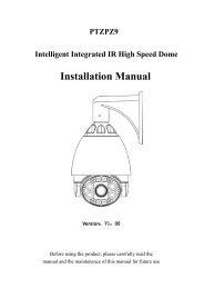
Dimensions<br />
30 www.digiop.com<br />
Top View<br />
Side View<br />
3/4” Tap<br />
Ø 3.94”<br />
5.94”<br />
4.47”
Base view<br />
Ø 4.53”<br />
~ Ø .15”<br />
APPENDIX B: DIMENSIONS<br />
1.24”<br />
3/4” Tap<br />
<strong>H.264</strong> <strong>Megapixel</strong> <strong>Indoor</strong>/<strong>Outdoor</strong> <strong>Dome</strong> <strong>IP</strong> <strong>Camera</strong><br />
31
APPENDIX C: POWER OVER ETHERNET<br />
APPENDIX C<br />
Power over Ethernet<br />
The BLK-<strong>IP</strong>D105M camera supports Power over Ethernet (PoE) in conformance with the IEEE 802.3af standard. IEEE 802.3af allows<br />
for two power options for Category 5 cables.<br />
• The PoE module signature and control circuit provides the PoE compatibility signature and power classification required by<br />
the Power Sourcing Equipment (PSE) before applying up to 15 W power to the port.<br />
• The high efficiency AC/DC converter operates over a wide input voltage range and provides a regulated low ripple and low<br />
noise output. The AC/DC converter also has built-in overload and short-circuit output protection.<br />
C.1 PoE compatibility<br />
With non Power Sourcing Equipment (PSE)<br />
When it is connected with non PSE, use the power adaptor to provide power to the camera.<br />
With power adaptor<br />
Connecting both PSE and power adaptor does not do any harm to the products. Disconnecting power adaptor while it is operating<br />
does not stop operation. The product continues to work without rebooting.<br />
C.2 Power classification<br />
The PoE Power Class supported by the <strong>IP</strong> device is Class 0.<br />
Class Usage Minimum Power Levels Output at the PSE Maximum Power Levels at the Powered Device<br />
0 Default 15.4 W 0.44 to 12.95 W<br />
32 www.digiop.com