condair sH2
condair sH2
condair sH2

You also want an ePaper? Increase the reach of your titles
YUMPU automatically turns print PDFs into web optimized ePapers that Google loves.
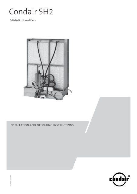
Condair SH2<br />
Adiabatic Humidifiers<br />
Installation and operating instructions<br />
2529324 EN 0810
Contents<br />
1 Introduction 4<br />
1.1 To the very beginning 4<br />
1.2 Notes on the installation and operating instructions 4<br />
2 For your safety 6<br />
5 Operation 48<br />
5.1 Putting into operation 48<br />
5.2 Adjust the volume controlling valves 48<br />
5.3 Notes on operation 49<br />
5.4 Taking out of operation 49<br />
3 Product overview 8<br />
3.1 Model overview 8<br />
3.2 Product designation 8<br />
3.3 Model “flow” 10<br />
3.3.1 Construction model “flow” 10<br />
3.3.2 System overview model “flow” 11<br />
3.4 Model “flow C” 12<br />
3.4.1 Construction model “flow C” 12<br />
3.4.2 System overview model “flow C” 13<br />
3.5 Model “flow SC” 14<br />
3.5.1 Construction Model “flow SC” 14<br />
3.5.2 System overview model “flow SC” 15<br />
3.6 Model “REflow” 16<br />
3.6.1 Construction model “REflow” 16<br />
3.6.2 System overview model “REflow” 17<br />
3.7 Model “REflow C” 18<br />
3.7.1 Construction model “REflow C” 18<br />
3.7.2 System overview model “REflow C” 19<br />
3.8 Model “REflow SC” 20<br />
3.8.1 Construction model “REflow SC” 20<br />
3.8.2 System overview model “REflow SC” 21<br />
3.9 Standard delivery 22<br />
3.10 Storing/Transport/Packaging 22<br />
6 Maintenance 50<br />
6.1 Important notes on maintenance 50<br />
6.2 Maintenance intervals 51<br />
6.3 Maintenance work 51<br />
6.4 Dismantling and installation works 53<br />
6.4.1 Dismantle and install the mist eliminator<br />
and humidification boxes 53<br />
6.4.2 Dismantle and install the UV lamp (option) 54<br />
6.5 Resetting the maintenance indication 54<br />
7 Malfunctions 55<br />
7.1 Malfunction list 55<br />
7.2 Notes on fault elimination 56<br />
8 Taking out of service/Disposal 57<br />
8.1 Taking out of service 57<br />
8.2 Disposal/Recycling 57<br />
9 Product specifications 58<br />
9.1 Technical data 58<br />
9.2 Unit dimensions 59<br />
4 Installation 23<br />
4.1 Important notes on the mounting and<br />
installation work 23<br />
4.2 Unit mounting 23<br />
4.2.1 Note on locating the unit 23<br />
4.2.2 Mounting process 25<br />
4.3 Water installation 38<br />
4.3.1 Overviews water installation 38<br />
4.3.2 Notes on water installation 41<br />
4.4 Electric installation 42<br />
4.4.1 Leading the electric cables out of the duct 42<br />
4.4.2 Mounting the control unit SH2 43<br />
4.4.3 Wiring diagram Condair SH2 flow C 44<br />
4.4.4 Wiring diagram Condair SH2 flow SC 45<br />
4.4.5 Wiring diagram Condair SH2 REflow C 46<br />
4.4.6 Wiring diagram Condair SH2 REflow SC 47
1 Introduction<br />
1.1 To the very beginning<br />
We thank you for having purchased the Adiabatic Air Humidifier Condair SH2.<br />
The adiabatic air humidifier Condair SH2 incorporates the latest technical advances and meets all<br />
recognized safety standards. Nevertheless, improper use of the adiabatic air humidifier Condair SH2<br />
may result in danger to the user or third parties and/or impairment of material assets.<br />
To ensure a safe, proper, and economical operation of the adiabatic air humidifier Condair SH2, please<br />
observe and comply with all information and safety instructions contained in the present installation<br />
and operating instructions as well as in the separate documentations of the components installed<br />
in the humidification system.<br />
If you have questions, which are not or insufficiently answered in this documentation, please contact<br />
your Condair supplier. They will be glad to assist you.<br />
1.2 Notes on the installation and operating instructions<br />
Limitation<br />
The subject of these installation and operating instructions is the adiabatic air humidifier<br />
Condair SH2. The various accessories are only described insofar as this is necessary for proper<br />
operation of the equipment. Further information on accessories can be obtained in the respective<br />
instructions.<br />
These installation and operating instructions are restricted to the installation, commissioning, operation,<br />
servicing, and trouble-shooting of the adiabatic air humidifier Condair SH2 and is meant<br />
for well trained personnel being sufficiently qualified for their respective work.<br />
The installation and operating instructions are supplemented by various separate items of documentation<br />
(spare parts list, manuals for accessories, etc.). Where necessary, appropriate cross-references<br />
are made to these publications in the installation and operating instructions.
Symbols used in this manual<br />
CAUTION!<br />
The catchword “CAUTION” designates notes in this installation and operating instructions<br />
that, if neglected, may cause damage and/or malfunction of the unit<br />
or other material assets.<br />
WARNING!<br />
The catchword “WARNING” used in conjunction with the general caution symbol<br />
designates safety and danger notes in this installation and operating instructions<br />
that, if neglected, may cause to injury to persons.<br />
DANGER!<br />
The catchword “DANGER” used in conjunction with the general caution symbol<br />
designates safety and danger notes in this installation and operating instructions<br />
that, if neglected, may lead to severe injury or even death of persons.<br />
Safekeeping<br />
Please safeguard these installation and operating instructions in a safe place, where they can be<br />
immediately accessed. If the equipment changes hands, the documentation must be passed on to<br />
the new operator.<br />
If the documentation gets mislaid, please contact your Condair supplier.<br />
Language versions<br />
These installation and operating instructions are available in various languages. Please contact your<br />
Condair supplier for information.<br />
Copyright protection<br />
The present installation and operating instructions is protected under the Copyright Act. Passing-on<br />
and reproduction of the manual (or part thereof) as well as exploitation and communication of the<br />
contents are prohibited without written permission by the manufacturer. Violation of copyright terms<br />
is subject to legal prosecution and arises liability for indemnification.<br />
The manufacturer reserves the right to fully exploit commercial patent rights.
2 For your safety<br />
General<br />
Every person working with the Condair SH2 must have read and understood the installation and<br />
operating instructions before carrying out any work.<br />
Knowing and understanding the contents of the installation and operating instructions is a basic<br />
requirement for protecting the personnel against any kind of danger, to prevent faulty operation, and<br />
to operate the unit safely and correctly.<br />
All ideograms, signs and markings applied to the unit must be observed and kept in readable<br />
state.<br />
Qualification of personnel<br />
All work (installation, operating, servicing , etc.) described in these installation and operating instructions<br />
may only be carried out by specialist who are well trained and adequately qualified and<br />
are authorized by the customer.<br />
For safety and warranty reasons any action beyond the scope of this manual must be carried out<br />
only by qualified personnel authorised by the manufacturer.<br />
It is assumed that all persons working with the Condair SH2 are familiar and comply with the appropriate<br />
regulations on work safety and the prevention of accidents.<br />
Intended use<br />
The adiabatic air humidifier/cooler Condair SH2 are intended exclusively for air humidification/air<br />
cooling in air ducts or monoblocs within the specified operating conditions (see chapter 9 “Product<br />
specifications”. Any other type of application, without the written consent of your Condair supplier,<br />
is considered as not conforming with the intended purpose and may lead to the Condair SH2<br />
becoming dangerous.<br />
Operation of the equipment in the intended manner requires that all the information in these<br />
instructions are observed (in particular the safety instructions).
Danger that may arise from the unit<br />
– Some components of the Condair SH2 are mains powered.<br />
DANGER!<br />
One may get in touch with live parts when the control unit or the distribution<br />
boxes are open. Touching live parts may cause severe injury or danger<br />
to life.<br />
Prevention:<br />
Before carrying out any work set the Condair SH2 out of operation as described<br />
in chapter 5.4 (switch off the unit, disconnect it from the mains and<br />
stop the water supply) and secure the unit against inadvertent power-up.<br />
– The UV lamp used in the water treatment unit (option) emits harmful UV-C rays.<br />
WARNING!<br />
If the UV lamp is operated outside the housing, the emitted UV-C rays may<br />
damage the eyes and the skin lasting.<br />
Prevention:<br />
Never operate the UV lamp outside the housing.<br />
– Badly maintained humidifiers can endanger the health.<br />
WARNING!<br />
Prevention:<br />
If the unit is insufficient maintained ill-making germs may grow in the water<br />
tub and the humidification boxes (and the mist eliminator) of the Condair<br />
SH2 and may can affect the air passing through the humidifier.<br />
The Condair SH2 must be cleaned in the prescribed intervals according to<br />
the information given in chapter 6 “Maintenance". The cleaning works must<br />
be carried out correctly and the humidification boxes and the mist eliminator<br />
boxes must be replaced after their prescribed lifetime has elapsed.<br />
Behaviour in case of danger<br />
If it is suspected that safe operation is no longer possible, then the Condair SH2 should immediately<br />
be shut down and secured against accidental power-up according to chapter 5.4. This can<br />
be the case under the following circumstances:<br />
– if the Condair SH2 is damaged<br />
– if the Condair SH2 is no longer operating correctly<br />
– if connections and/or piping are not sealed<br />
– if electrical cables are defective<br />
All persons working with the Condair SH2 must report any alterations to the unit that may affect<br />
safety to the owner without delay.<br />
Prohibited modifications to the unit<br />
No modifications must be undertaken on the Condair SH2 without the express written consent<br />
of the manufacturer.<br />
For the replacement of defective components use exclusively original accessories and spare parts<br />
available from your Condair supplier.
3 Product overview<br />
3.1 Model overview<br />
The Condair SH2 is available in the two base versions “flow” with direct water system and “REflow”<br />
with circulating water system. The following base models are available:<br />
– Condair SH2 flow<br />
– Condair SH2 flow C (with control unit RC and On/Off control)<br />
– Condair SH2 flow SC (with control unit SH2 and step control)<br />
– Condair SH2 REflow<br />
– Condair SH2 REflow C (with control unit SH2 and On/Off control)<br />
– Condair SH2 REflow SC (with control unit SH2 and step control)<br />
All base models can be extended in their functions by different options. In addition there are different<br />
accessories available for all models.<br />
3.2 Product designation<br />
The product designation and the most important unit data are found on the rating plate:<br />
Type designation Serial number Month/Year<br />
Supply voltage<br />
Humidification capacity<br />
Admissible water supply pressure<br />
Certificates<br />
Type key<br />
Walter Meier (Climate International) Ltd. 8808 Pfäffikon, Switzerland<br />
SH2 REflow SC<br />
XXXXXXX 03.07<br />
230V 1~ / 50Hz<br />
393 VA<br />
Befeuchtungsleistung = 150.0 kg/h REflow SC 300 1800 2000 1 150<br />
Fliessdruck 2...10 bar max. 45°C<br />
Made in Switzerland<br />
Power consumption
Type key<br />
Example:<br />
Condair SH2 REflow SC 300 1800 2000 0 150<br />
Model:<br />
flow<br />
flow C<br />
flow SC<br />
REflow<br />
REflow C<br />
REflow SC<br />
Depth of humidification box:<br />
200 mm<br />
300 mm<br />
Order code width W<br />
Order code height H<br />
Mist eliminator:<br />
No mist eliminator: 0<br />
Mist eliminator 100 mm: 1<br />
Mist eliminator 200 mm: 2<br />
Humidification capacity in kg/h according layout
10<br />
3.3 Model “flow”<br />
3.3.1 Construction model “flow”<br />
6<br />
7<br />
8<br />
5<br />
2<br />
1<br />
4<br />
3<br />
1 Water connection on unit R 3/4" (outside thread)<br />
2 Volume controlling valves (adjustable manually)<br />
3 Water tub<br />
4 Open drain (ø 40/34 mm)<br />
5 Water hoses<br />
6 Trickling hoods with distribution pipes<br />
7 Humidification boxes<br />
8 Mist eliminator (for air speed above humidification boxes >3.8 m/s)
11<br />
3.3.2 System overview model “flow”<br />
Volume controlling valves<br />
(adjustable manually)<br />
Humidification boxes<br />
Water tub<br />
Open drain<br />
Water connection unit (accessory)<br />
Water filter<br />
Siphon (building side)<br />
Pressure reducing valve<br />
Drain funnel (building side)<br />
Shut-off valve<br />
Control: via humidistat that actuates the supply valve depending on the humidification requests<br />
Water supply<br />
2...10 bar<br />
Functional description<br />
In case of a humidification/cooling request the supply valve (accessory) opens and the water flows<br />
via the pressure reducing valve (accessory), the water filter (accessory) and the manually adjustable<br />
volume controlling valves to the distribution pipes above the humidification boxes.<br />
The distribution pipes evenly supply the water to the entire surface of the humidification boxes where<br />
it flows down and humidifies the air flowing through the humidification boxes. The excess water not<br />
used for humidification flows to the water tub and then directly to the drain.
12<br />
3.4 Model “flow C”<br />
3.4.1 Construction model “flow C”<br />
9<br />
6<br />
7<br />
8<br />
5<br />
1<br />
2<br />
4<br />
3<br />
1 Water connection on unit R 3/4" (outside thread)<br />
2 Volume controlling valves (adjustable manually)<br />
3 Water tub<br />
4 Open drain (ø 40/34 mm)<br />
5 Water hoses<br />
6 Trickling hoods with distribution pipes<br />
7 Humidification boxes<br />
8 Mist eliminator (for air speed above humidification boxes >3.8 m/s)<br />
9 Control unit RC
13<br />
3.4.2 System overview model “flow C”<br />
Volume controlling valves<br />
(adjustable manually)<br />
Humidification boxes<br />
Supply valve<br />
Water tub<br />
Water connection unit (accessory)<br />
Water filter<br />
Control unit RC<br />
Output:<br />
Supply valve<br />
Open drain<br />
Siphon (building side)<br />
Pressure reducing valve<br />
L1 N S S<br />
Drain funnel (building side)<br />
Shut-off valve<br />
Humidistat 230V/2A<br />
%rH<br />
Water supply<br />
2...10 bar<br />
Input:<br />
Potential free contact 230 V<br />
PE L1 N<br />
Functional description<br />
The “flow C” model provides On/Off control by means of the RC control unit and an external On/Off<br />
humidistat. In case of a humidification/cooling request the supply valve opens and the water flows<br />
via the pressure reducing valve (accessory), the water filter (accessory) and the manually adjustable<br />
volume controlling valves to the distribution pipes above the humidification boxes.<br />
The distribution pipes evenly supply the water to the entire surface of the humidification boxes where<br />
it flows down and humidifies the air flowing through the humidification boxes. The excess water not<br />
used for humidification flows to the water tub and then directly to the drain.
14<br />
3.5 Model “flow SC”<br />
3.5.1 Construction Model “flow SC”<br />
7<br />
11<br />
8<br />
9<br />
10<br />
6<br />
2<br />
3<br />
1<br />
5<br />
4<br />
1 Water connection on unit R 3/4" (outside thread)<br />
2 Volume controlling valves (adjustable manually)<br />
3 Step valves (1 to 3)<br />
4 Water tub<br />
5 Open drain (ø 40/34 mm)<br />
6 Water hoses<br />
7 Trickling hoods with distribution pipes<br />
8 Humidification boxes<br />
9 Mist eliminator (for air speed above humidification boxes >3.8 m/s)<br />
10 UV water treatment (option)<br />
11 Control unit SH2
15<br />
3.5.2 System overview model “flow SC”<br />
Humidification boxes<br />
UV water treatment<br />
(option)<br />
Minimum<br />
pressure switch<br />
Volume controlling valves<br />
(adjustable manually)<br />
Rinsing valve<br />
Step valves 1..3<br />
Water tub<br />
Water connection unit<br />
(standard delivery **)<br />
** installation mandatory<br />
Open drain<br />
Water filter<br />
Pressure reducing valve<br />
Inputs<br />
Outputs<br />
Minimum pressure<br />
Siphon (building side)<br />
Control unit SH2<br />
Drain funnel (building side)<br />
Shut-off valve<br />
Display<br />
Step valves 1...3<br />
Water supply<br />
2...10 bar<br />
Error<br />
Humidification<br />
UV water treatment<br />
Remote indication (On, Error, Maintenance and Humidification)<br />
Control/sensor signal analog<br />
0...5 VDC, 1...5 VDC, 0...10 VDC<br />
2...10 VDC, 0..16 VDC, 3.2...16 VDC,<br />
0..20 mA, 4..20 mA<br />
Functional description<br />
The “flow SC” model provides multistep control by means of the SH2 control unit and the step<br />
valves (1, 2 or 3 step valves depending on the humidifier capacity). The SH2 control unit (for wall<br />
mounting) processes analog sensor/control signals and uses them to control the step valves. This<br />
allows multistep control (1 to 3 steps depending on the humidifier capacity) which improves control<br />
accuracy compared to the “flow” model.<br />
In case of a humidification/cooling request one, two or all three step valves open (depending on the<br />
request). The water flows via the manually adjustable volume controlling valves to the distribution<br />
pipes above the humidification boxes.<br />
The distribution pipes evenly supply the water to the entire surface of the humidification boxes where<br />
it flows down and humidifies the air flowing through the humidification boxes. The excess water not<br />
used for humidification flows to the water tub and then directly to the drain.<br />
If the “flow SC” model is equipped with the optional UV water treatment (installed in the water<br />
supply) the water is continuously degerminated during the humidification process.
16<br />
3.6 Model “REflow”<br />
3.6.1 Construction model “REflow”<br />
11<br />
12<br />
13<br />
10<br />
1<br />
2<br />
4<br />
5<br />
9<br />
3<br />
7<br />
6<br />
8<br />
1 Water connection on unit R 3/4" (outside thread)<br />
2 Level-controlled supply valve<br />
3 Circulation pump<br />
4 Volume controlling valves (adjustable manually)<br />
5 Overflow<br />
6 Drain (ø 40/34 mm)<br />
7 Shut-off valve<br />
8 Water tub<br />
9 Drain line<br />
10 Water hoses<br />
11 Trickling hoods with distribution pipes<br />
12 Humidification boxes<br />
13 Mist eliminator (for air speed above humidification boxes >3.8 m/s)<br />
CAUTION!<br />
The circulation pump must be protected against dry operation by taking appropriate<br />
measures (by the customer).
17<br />
3.6.2 System overview model “REflow”<br />
Humidification boxes<br />
Volume controlling valves<br />
(adjustable manually)<br />
Level-controlled<br />
supply valve<br />
Circulation pump<br />
Water level<br />
Overflow<br />
Water tub<br />
Water connection unit (accessory)<br />
Shut-off valve<br />
Water filter<br />
Pressure reducing valve<br />
Shut-off valve<br />
Control:<br />
Via humidistat switching the circulation pump on or off depending on humidification<br />
request<br />
Draining:<br />
Draining is done continuously via the volume controlling valve (to the very right).<br />
Siphon (building side)<br />
Drain funnel (building side)<br />
Water supply<br />
2...10 bar<br />
Functional description<br />
The water tub is filled up to a preset upper level via the level-controlled supply valve. When the water<br />
level in the tub drops below a certain limit, the level-controlled supply valve opens until the upper<br />
limit is reached again.<br />
In case of a humidification/cooling request the circulation pump starts and supplies the water via<br />
the manually adjustable volume controlling valves to the distribution pipes above the humidification<br />
boxes.<br />
The distribution pipes evenly supply the water to the entire surface of the humidification boxes where<br />
it flows down and humidifies the air flowing through the humidification boxes. The excess water not<br />
used for humidification flows to the water tub and is fed back to the circulation pump.<br />
To prevent accumulation of mineral residues in the water tub, a limited amount of water is continuously<br />
drained via a manually adjustable volume controlling valve and replaced with fresh water.
18<br />
3.7 Model “REflow C”<br />
3.7.1 Construction model “REflow C”<br />
10<br />
13<br />
11<br />
12<br />
9<br />
2<br />
1<br />
7<br />
4<br />
3<br />
6<br />
8<br />
5<br />
1 Water connection on unit R 3/4" (outside thread)<br />
2 Level-controlled supply valve<br />
3 Circulation pump<br />
4 Overflow<br />
5 Drain (ø 40/34 mm)<br />
6 Drain valve<br />
Volume controlling valves (adjustable manually)<br />
8 Water tub<br />
9 Water hoses<br />
10 Trickling hoods with distribution pipes<br />
11 Humidification boxes<br />
12 Mist eliminator (for air speed above humidification boxes >3.8 m/s)<br />
13 Control unit SH2
19<br />
3.7.2 System overview model “REflow C”<br />
Humidification boxes<br />
Level-controlled<br />
supply valve<br />
Level switch<br />
Conductivity monitoring<br />
(option)<br />
Volume controlling valves<br />
(adjustable manually)<br />
Circulation pump<br />
Overflow<br />
Water tub<br />
Operating level = pump immediately on / delayed off<br />
Water connection unit (accessory)<br />
Water filter<br />
Pressure reducing valve<br />
Inputs<br />
Outputs<br />
Conductivity (option)<br />
Operating level<br />
Drain valve<br />
Siphon (building side)<br />
Water supply<br />
2...10 bar<br />
Stop valve<br />
Control unit SH2<br />
Display<br />
Error<br />
Humidification<br />
Drain funnel (building side)<br />
Supply valve<br />
Drain valve<br />
Circulation pump<br />
Signal On/Off humidistat<br />
Remote indication (On, Error, Maintenance and Humidification)<br />
Functional description<br />
The water tub is filled up to a preset upper level via the level-controlled supply valve. When the water<br />
level in the tub drops below a certain limit, the level-controlled supply valve opens until the upper<br />
limit is reached again.<br />
The “REflow C” model provides On/Off control by means of the SH2 control unit and an external<br />
On/Off humidistat. In case of a humidification/cooling request one, two or all three step valves open<br />
(depending on the request). The water flows via the manually adjustable volume controlling valves<br />
to the distribution pipes above the humidification boxes.<br />
The distribution pipes evenly supply the water to the entire surface of the humidification boxes where<br />
it flows down and humidifies the air flowing through the humidification boxes. The excess water not<br />
used for humidification flows to the water tub.<br />
To prevent accumulation of mineral residues and the formation of germs in the water tub, the tub<br />
is completely drained periodically (interval or time controlled). Additionally further hygiene functions<br />
can be activated: Operation-dependent draining of the water tub (conductivity or fill cycle controlled)<br />
as well as cleaning and drying of the humidification boxes.
20<br />
3.8 Model “REflow SC”<br />
3.8.1 Construction model “REflow SC”<br />
11<br />
15<br />
12<br />
13<br />
14<br />
10<br />
2<br />
1<br />
8<br />
7<br />
3<br />
4<br />
6<br />
5<br />
9<br />
1 Water connection on unit R 3/4" (outside thread)<br />
2 Level-controlled supply valve<br />
3 Circulation pump<br />
4 Overflow<br />
5 Drain (ø 40/34 mm)<br />
6 Drain valve<br />
Step valves (1 to 3)<br />
8 Volume controlling valves (adjustable manually)<br />
9 Water tub<br />
10 Water hoses<br />
11 Trickling hoods with distribution pipes<br />
12 Humidification boxes<br />
13 Mist eliminator (for air speed above humidification boxes >3.8 m/s)<br />
14 UV water treatment (option)<br />
15 Control unit SH2
21<br />
3.8.2 System overview model “REflow SC”<br />
Level-controlled<br />
supply valve<br />
Humidification boxes<br />
Level switch<br />
UV water treatment<br />
(option)<br />
Conductivity monitoring<br />
(option)<br />
Circulation pump<br />
Volume controlling valves<br />
(adjustable manually)<br />
Step valves 1..3<br />
Overflow<br />
Water tub<br />
Operating level = pump immediately on / delayed off<br />
Water connection unit (accessory)<br />
Drain valve<br />
Water filter<br />
Conductivity (option)<br />
Operating level<br />
Pressure reducing valve<br />
Inputs<br />
Outputs<br />
Siphon (building side)<br />
Water supply<br />
2...10 bar<br />
Stop valve<br />
Control unit SH2<br />
Display<br />
Error<br />
Humidification<br />
Drain funnel (building side)<br />
Step valves 1...3<br />
UV water treatment<br />
Supply valve<br />
Drain valve<br />
Circulation pump<br />
Remote indication (On, Error, Maintenance and Humidification)<br />
Control/sensor signal analog<br />
0...5 VDC, 1...5 VDC, 0...10 VDC,<br />
2...10 VDC, 0..16 VDC, 3.2...16 VDC,<br />
0..20 mA, 4..20 mA<br />
Functional description<br />
The water tub is filled up to a preset upper level via the level-controlled supply valve. When the water<br />
level in the tub drops below a certain limit, the level-controlled supply valve opens until the upper<br />
limit is reached again.<br />
The “REflow SC” model provides multistep control by means of the SH2 control unit and the step<br />
valves (1, 2 or 3 step valves depending on the humidifier capacity). The SH2 control unit (for wall<br />
mounting) processes analog sensor/control signals and uses them to control the step valves. This<br />
allows multistep control (1 to 3 steps depending on the humidifier capacity) which improves control<br />
accuracy compared to the “REflow” model.<br />
In case of a humidification/cooling request the circulation pump starts and one, two or all three<br />
step valves open (depending on the request). The water flows via the manually adjustable volume<br />
controlling valves to the distribution pipes above the humidification boxes.<br />
The distribution pipes evenly supply the water to the entire surface of the humidification boxes where<br />
it flows down and humidifies the air flowing through the humidification boxes. The excess water not<br />
used for humidification flows to the water tub.
22<br />
To prevent accumulation of mineral residues and the formation of germs in the water tub, the tub<br />
is completely drained periodically (Interval or time controlled). Additionally further hygiene functions<br />
can be activated: Operation-dependent draining of the water tub (conductivity or fill cycle controlled)<br />
as well as cleaning and drying of the humidification boxes.<br />
If the “REflow SC” model is equipped with the optional UV water treatment, a particular amount of<br />
water is led to the UV water treatment unit where it is degerminated.<br />
3.9 Standard delivery<br />
The standard delivery includes:<br />
– Adiabatic air humidifier Condair SH2 according type designation (delivered apart) equipped with<br />
options according delivery note.<br />
– Ordered accessories with operating instructions, packed separately.<br />
– Installation and operating instructions (this document)<br />
– Operating instructions control unit SH2 (models with control unit SH2 only)<br />
– Spare parts list<br />
3.10 Storing/Transport/Packaging<br />
Storing<br />
Store the unit and unit components in a protected area meeting the following requirements:<br />
– room temperature: 1 ... 40 °C<br />
– room humidity: 10 ... 75 %rh<br />
Transport<br />
For optimum protection always transport the unit and the unit components in the original packaging.<br />
The weight of the unit components depends on the unit model. To transport bigger unit components<br />
always ask a second person for assistance.<br />
Packaging<br />
Keep the original packaging of the Condair SH2 for later use.<br />
In case you wish to dispose of the packaging, observe the local regulations on waste disposal. Never<br />
dispose of the packaging to the environment.
23<br />
4 Installation<br />
4.1 Important notes on the mounting and installation work<br />
Qualification of personnel<br />
All mounting and installation work must be carried out only by well qualified personnel authorised<br />
by the owner. It is the owner’s responsibility to verify proper qualification of the personnel.<br />
General note<br />
Strictly observe and comply with all information given in the present installation and operating<br />
instructions regarding the mounting of the unit and the installation of water and electricity.<br />
Observe and comply with all local regulations dealing with water and electrical installations.<br />
Safety<br />
The electrical installation for the unit models flow C, flow SC, REflow C and REflow SC requires the<br />
removal of the control unit cover. Please note the following:<br />
DANGER!<br />
CAUTION!<br />
Danger of electrical shock! You may get in touch with live parts when the control<br />
unit is open. The control unit must be connected to the mains only after<br />
all mounting and installation work has been completed and the control unit<br />
cover has been relocated properly.<br />
The electronic components inside the control unit are very sensitive to electrostatic<br />
discharge. When the unit is open for installation work, appropriate measures must<br />
be taken to protect these components against damage caused by electrostatic<br />
discharge (ESD protection).<br />
4.2 Unit mounting<br />
4.2.1 Note on locating the unit<br />
Usually, the design and dimensioning of the ventilation duct/monobloc as well as the location of<br />
the Condair SH2 inside the duct are determined, recorded and set compulsory when planning the<br />
entire system. Prior to installation, however, make sure the following criteria have been taken into<br />
consideration:<br />
– For operation with fully demineralised water: Fully demineralised water is aggressive! For this<br />
reason, all components located close to the humidification unit (duct/monobloc, fastening material,<br />
drain pipe, etc.) must be made of corrosion-proof steel (minimum requirements according<br />
to DIN 1.4301) or plastic.<br />
– For installation and maintenance of the humidification unit a viewing window and a sufficiently<br />
large maintenance door (min. width= installation depth Condair SH2, see chapter 9.2) must be<br />
available in the duct/monobloc.<br />
– In the area of the humidification unit the ventilation duct/monobloc must be waterproof.<br />
– In the area of the humidification unit the duct floor must offer a plane support (plane duct floor or<br />
profile construction), which is lengthwise and crosswise horizontal aligned and has a sufficient<br />
load-bearing capacity to support the humidifier unit.
24<br />
– We recommend to install air filter (quality standard F7 (EU7) or better) before the humidification<br />
unit. The operation without air filter or with a filter of lower quality is possible, this can however,<br />
depending on the air quality, lead to an increased contamination of the humidifier boxes and thus<br />
to a reduction of the performance/lifetime.<br />
– In case of low ambient temperature the duct must be insulated to prevent the moist air from<br />
condensing inside the duct.<br />
– If the system is equipped with a heater, make sure it is at least 0.5 m away from the humidification<br />
unit.<br />
– If silencers are mounted in the airconditioning units make sure to locate the humidification unit<br />
at a minimum distance of 3 m before or after the silencers.<br />
– In order to avoid drops seeping over the humidification boxes, an even air flow over the full cross<br />
section of the humidification unit must be guaranteed. If necessary, rectifiers or perforated plates<br />
must be installed on the building side before the humidifier.<br />
If the air velocity above the humidification boxes exceeds 3.8 m/s, mist eliminator must be installed.<br />
– The effective height of the siphon in the drain line depends on the duct pressure. Correct dimensioning<br />
of the siphon is the customer’s responsibility.
25<br />
4.2.2 Mounting process<br />
A<br />
A<br />
1. Fix the two mounting brackets “A” to the water tub using one nut M6 and washer for each<br />
bracket. Align the water tub to the centre of the duct, then use the spirit level to adjust the water<br />
tub to the duct lengthwise and crosswise. When adjusted, fix the mounting brackets to the duct<br />
wall using two self-tapping screws 5.5x19.<br />
Note: Alternatively the water tub can be fixed directly to the duct floor/support construction with<br />
four self-tapping screws 5.5x19 on each side.<br />
B<br />
2. Fix the cross beam “B” to the water tub using four hexagon socket screws M6x12 and washers.
26<br />
D<br />
E<br />
Hint: With close space conditions we recommend to install the EPDM sealing profile to the vertical<br />
supports before installing the supports. Please refer to step 7 for more information.<br />
3. Carefully mount the left “D” and the right vertical support “E” onto the threaded bolts of the<br />
water tub, then fix each support with four nuts M6 and washers (do not overtighten the nuts).<br />
Important! Before tightening the nuts make sure the holes of the vertical supports seat solidly<br />
on the sheet metal of the water tub and do not stuck on the collar of the threaded bolt!
27<br />
F<br />
4. Carefully mount the vertical intermediate support(s) “F” (number depending on the unit size)<br />
onto the threaded bolts of the water tub, then fix each support with two nuts M6 and washers<br />
to the water tub (do not overtighten the nuts) and with a hexagon socket screw M6x12 and a<br />
washer to the cross beam.<br />
Important! Before tightening the nuts make sure the holes of the intermediate support seat<br />
solidly on the sheet metal of the water tub and do not stuck on the collar of the threaded bolt!
28<br />
G<br />
5. Fix the front bracket “G” to each vertical support using two hexagon socket screws M6x12 and<br />
washers.<br />
Important! Before tightening the screws make sure all supports are vertically exactly aligned!
29<br />
H<br />
H<br />
H<br />
6. Fix one mounting bracket “H” to each vertical support and intermediate support using a hexagon<br />
socket screw M6x12, a nut M6 and a washer (see figure above). Important: With multiple intermediate<br />
supports all mounting brackets must be mounted to the supports on the same side. The<br />
mounting brackets fixed to the outermost supports must be mounted always outside (between<br />
duct wall and support) and point inward.<br />
Finally align the supports, then fix the mounting brackets to the duct ceiling using two self-tapping<br />
screws 5.5x19 each.
30<br />
7. The air gap between the outermost vertical supports and the duct walls as well as between the<br />
front bracket and the duct ceiling must be sealed using EPDM sealing profile (accessory).<br />
Cut the EPDM sealing profiles to the desired length (channel height and channel width plus 5 cm<br />
allowance). Fix the EPDM sealing profiles to the outermost vertical supports and to the front<br />
bracket using the clamping brackets and self-tapping screws 5.5x19 supplied. Tailor the EPDM<br />
sealing profiles to the duct height and the duct width, then fix them to the duct walls and the<br />
duct ceiling using the clamping brackets and self-tapping screws 5.5x19 supplied (number of<br />
self-tapping screws to be used as required).<br />
Note: In place of the EPDM sealing profiles also sheet metal angles of stainless steel (not included<br />
in the delivery) may be used for the sealing.
31<br />
H<br />
8. Fix hydraulic unit to the water tub and the cross beam using four hexagon socket screws M6x12<br />
and washers.<br />
Important: Remove the closing plug “H” from the circulation pump inlet before mounting<br />
the hydraulic units REflow, REflow C or REflow SC.
32<br />
flow<br />
flow C<br />
flow SC<br />
REflow<br />
REflow C<br />
REflow SC<br />
remains<br />
open<br />
Important:<br />
Insert the hose at least<br />
20–30 mm into the opening!<br />
9. Assemble the drains according to the corresponding figure above (the drains can be assembled<br />
for draining to the right or to the left) and fix it to the connector(s) of the water tub. Fasten all<br />
threaded connections and hose clamps and fix the drain pipe to the water tub with the pipe support<br />
supplied.
33<br />
K<br />
10. Starting from the bottom, install the humidification boxes in each row: Hook the mounting clips<br />
of the boxes into the corresponding openings of the supports, then push the humidification box<br />
downwards until it comes to a stop (arrangement of the humidification boxes according to the<br />
installation drawing included in the delivery).<br />
Note: in ventilation systems with an air speed >4.7 m/s the cover sheet “K” must be mounted<br />
to all topmost humidification boxes before installing them.
34<br />
11. Only for units with mist eliminator: Hook the mounting brackets into corresponding openings<br />
of the vertical supports, then push the brackets downwards until it comes to a stop (if necessary<br />
use a rubber mallet).<br />
Note: arrangement of the mounting brackets according to the detail figures above and the installation<br />
drawing included in the delivery.
12. Only for units with mist eliminator: Starting from the bottom, install the mist eliminator in<br />
each row: Hook the mounting clips of the mist eliminator into the corresponding openings of the<br />
mounting brackets, then push the mist eliminator downwards until it comes to a stop.<br />
Note: arrangement of the mist eliminator according to the installation drawing included in the<br />
delivery.<br />
35
36<br />
13. Mounting the trickling hoods: Push the two tongues on the back side of the trickling hood underneath<br />
the frame sheet of the humidification box (see detail above), then flap the trickling hood<br />
downwards. The two brackets on the front side of the trickling hood must engage in the frame<br />
(see detail above) of the humidification box.<br />
Note: arrangement of the trickling hoods according to the installation drawing included in the<br />
delivery.
14. Remove the closing plugs from the connections of the hydraulic unit. Cut the water hoses to the<br />
required length. Connect water hoses to the connectors on the trickling hoods and the volume<br />
controlling valves and fix them with the hose clamps.<br />
Note: arrangement of the water hoses according to the installation drawing included in the delivery.<br />
37
38<br />
4.3 Water installation<br />
4.3.1 Overviews water installation<br />
Model “flow”<br />
R 3/4"<br />
ø 40/34 mm<br />
Drain line with constant down-slope<br />
Siphon (building side, height<br />
adjusted to the duct pressure)<br />
Open funnel (building side)<br />
Water connection unit (accessory)<br />
Water filter<br />
Pressure reducing valve<br />
Shut-off valve<br />
Model “flow C”<br />
Water supply<br />
2...10 bar<br />
5...45 °C<br />
R 3/4"<br />
Water connection unit (accessory)<br />
Water filter<br />
Pressure reducing valve<br />
Shut-off valve<br />
Water supply<br />
2...10 bar<br />
5...45 °C<br />
ø 40/34 mm<br />
Drain line with constant down-slope<br />
Siphon (building side, height<br />
adjusted to the duct pressure)<br />
Open funnel (building side)
39<br />
Model “flow SC”<br />
R 3/4"<br />
** installation mandatory<br />
ø 40/34 mm<br />
Drain line with constant down-slope<br />
Siphon (building side, height<br />
adjusted to the duct pressure)<br />
Open funnel (building side)<br />
Water connection unit **<br />
(standard delivery)<br />
Water filter<br />
Pressure reducing valve<br />
Shut-off valve<br />
Water supply<br />
2...10 bar<br />
5...45 °C<br />
Model “REflow”<br />
R 3/4"<br />
Water connection unit (accessory)<br />
Water filter<br />
Pressure reducing valve<br />
Shut-off valve<br />
Water supply<br />
2...10 bar<br />
5...45 °C<br />
Insert drain hose at least<br />
20–30 mm into the opening<br />
ø 40/34 mm<br />
Drain line with constant down-slope<br />
Siphon (building side, height<br />
adjusted to the duct pressure)<br />
Open funnel (building side)
40<br />
Models “REflow C” and “REflow SC”<br />
R 3/4"<br />
Water connection unit (accessory)<br />
Water filter<br />
Pressure reducing valve<br />
Shut-off valve<br />
Water supply<br />
2...10 bar<br />
5...45 °C<br />
ø 40/34 mm<br />
Drain line with constant down-slope<br />
Siphon (building side, height<br />
adjusted to the duct pressure)<br />
Open funnel (building side)
41<br />
4.3.2 Notes on water installation<br />
Water supply<br />
The water supply is to be carried out according to the figure found in chapter 4.3.1 and the applicable<br />
local regulations for water installations. The indicated connection specifications must be observed.<br />
– The installation of the shut-off valve, pressure reducing valve and a water filter should be<br />
made as close as possible to the unit.<br />
– Notes on water quality:<br />
– For the water supply of the Condair SH2, use exclusively untreated drinking water, fully<br />
demineralised water or partly softened water with a max of 100 cfu/ml.<br />
– The use of additives such as corrosion inhibitors, disinfectants, etc. is not allowed, since<br />
these additives may endanger health and affect proper operation.<br />
– If the Condair SH2 shall be operated with softened water, please contact your Condair supplier.<br />
– The connection material must be pressure-proof and certified for use in drinking water supply systems.<br />
– Important! Before connecting the water line to the unit, the line must be flushed thoroughly.<br />
CAUTION!<br />
The thread at the humidifier connection is made of plastic. To avoid overtightening,<br />
the union nut of the water pipe must be tightened by hand only.<br />
Water drain<br />
The water drain is to be carried out according to the figure found in chapter 4.3.1 and the applicable<br />
local regulations for water installations. The indicated connection specifications must be observed.<br />
– Make sure the drain line is installed with a constant down-slope to the siphon of the building.<br />
– Make sure the drain pipe is correctly fixed and easily accessible for inspections and cleaning purposes.<br />
– The minimum inside diameter of the drain pipe of 34 mm must be maintained throughout the<br />
entire length!<br />
When operating the Condair SH2 with fully demineralised water:<br />
Fully demineralised water is aggressive! For this reason, use exclusively plastic or stainless steel<br />
installation materials (min. DIN 1.4301).
42<br />
4.4 Electric installation<br />
Note: the electric installation of the unit models Condair SH2 “flow” and “REflow” is by the clients<br />
responsibility.<br />
4.4.1 Leading the electric cables out of the duct<br />
Lead the cable(s) of the connecting boxe(s) via cable gland(s) out of the duct.
43<br />
4.4.2 Mounting the control unit SH2<br />
CAUTION!<br />
The electronic components inside the control unit are very sensitive to electrostatic<br />
discharge. When the unit is open for installation work, appropriate measures must<br />
be taken to protect these components against damage caused by electrostatic<br />
discharge (ESD protection).<br />
2.<br />
236 mm<br />
220 mm<br />
3.<br />
306 mm<br />
280 mm<br />
1.<br />
Detail “B”<br />
Detail “A”<br />
1. Unlock and swivel up the transparent cover, then unlock the two hinges (see detail “A”) and remove<br />
the cover.<br />
2. Undo the 6 screws, then carefully lift the control unit cover and disconnect the cables on the<br />
electronic.<br />
3. Break out the 4 oblong holes in the bottom of the unit housing and fix the control unit to the wall<br />
using 4 screws.<br />
4. Connect the cables from the connecting box(es), the voltage supply, etc. to the corresponding<br />
terminals in the control unit according the appropriate wiring diagram (see chapter 4.4.3, 4.4.4,<br />
4.4.5 and 4.4.6).<br />
Important: all cables must be lead into the control unit via the cable glands in the housing.
44<br />
4.4.3 Wiring diagram Condair SH2 flow C<br />
Y1<br />
B1<br />
B2<br />
F6<br />
Y1<br />
Control unit RC<br />
Q<br />
L1 N S S<br />
B1<br />
%rH<br />
cross section 1.5 mm 2<br />
Humidistat or thermostat (230V/2A)<br />
Safety humidistat (Safety chain)<br />
Fuse 2 A, slow acting (voltage supply)<br />
Inlet valve<br />
Service switch (min. contact opening 3 mm) or<br />
plug connection (installation mandatory)<br />
B2<br />
%rH<br />
Q<br />
F6<br />
PE L1 N
45<br />
4.4.4 Wiring diagram Condair SH2 flow SC<br />
-<br />
Y<br />
+<br />
B1<br />
B4<br />
Clean Trg. 1:<br />
e.Demand<br />
brown<br />
white<br />
brown<br />
white<br />
P<br />
GND<br />
0-10V<br />
N<br />
P1<br />
GND<br />
Input+<br />
5V/24V<br />
F4<br />
200mAF<br />
L1 N L1 N<br />
24V<br />
5V<br />
+24V<br />
F1<br />
6.3AT<br />
Res1<br />
Res2<br />
Level max<br />
level min / PS<br />
Connector<br />
to CPU<br />
+24V<br />
L1<br />
N<br />
SC<br />
SC<br />
PT1<br />
PT2<br />
F3<br />
630mAT<br />
F2<br />
1AT<br />
Reserve<br />
Output<br />
N<br />
UV Lamp N<br />
Drain Valve<br />
Inlet Valve<br />
N<br />
Stage 3<br />
Stage 2<br />
Stage 1<br />
N<br />
Pump<br />
7<br />
6<br />
5<br />
PE<br />
4 (N)<br />
3<br />
2<br />
1<br />
brown<br />
PS<br />
V<br />
Y2<br />
Y5<br />
Y4<br />
Y3<br />
blue<br />
N<br />
Modul B<br />
S2<br />
1<br />
4<br />
Front panel<br />
J<br />
2<br />
5<br />
Connecting box<br />
H<br />
Error<br />
Service<br />
Humidification<br />
Unit On<br />
L1 N<br />
B2<br />
Q<br />
cross section 1.5 mm 2<br />
F6<br />
PE L1 N<br />
B1 Active controller or humidity sensor<br />
B2 Ventilator interlock (safety chain)<br />
B4 Potential free contact, to trigger a “Box cleaning cycle”<br />
F1 Fuse 6.3 A, slow acting (Voltage supply control unit)<br />
F2 Fuse 1 A, slow acting (Relay 230 V)<br />
F3 Fuse 630 mA, slow acting (Step valves)<br />
F4 Fuse 200 mA, fast acting (Analog entry)<br />
F6 Fuse 10 A, slow acting (Voltage supply)<br />
H Remote operating and fault indication (Option)<br />
J Cable bridge (must be removed, if “B2” is connected)<br />
PS Pressure switch<br />
S2 Unit switch<br />
Y2 Rinsing valve<br />
Y3-Y5 Step valves<br />
Q Service switch (min. contact opening 3 mm) or<br />
plug connection (installation mandatory)<br />
V UV lamp for water sterilisation (Option)
46<br />
4.4.5 Wiring diagram Condair SH2 REflow C<br />
B1<br />
B4<br />
Clean Trg. 1:<br />
e.Demand<br />
P<br />
Modul B<br />
white<br />
green<br />
GND<br />
0-10V<br />
N<br />
P1<br />
S2<br />
GND<br />
Input+<br />
5V/24V<br />
1<br />
2<br />
F4<br />
200mAF<br />
4<br />
5<br />
brown<br />
L1 N L1 N<br />
24V<br />
5V<br />
Front panel<br />
+24V<br />
F1<br />
6.3AT<br />
Res1<br />
Res2<br />
Level max<br />
level min / PS<br />
Connector<br />
to CPU<br />
L1<br />
N<br />
SC<br />
SC<br />
PT1<br />
PT2<br />
J<br />
+24V<br />
green<br />
brown<br />
white<br />
K<br />
F3<br />
630mAT<br />
F2<br />
1AT<br />
Reserve<br />
Output<br />
N<br />
UV Lamp N<br />
Drain Valve<br />
Inlet Valve<br />
1 3 5 13<br />
N<br />
Stage 3<br />
Stage 2<br />
Stage 1<br />
N<br />
Pump<br />
A1<br />
A2<br />
7<br />
6<br />
5<br />
PE<br />
4 (N)<br />
3<br />
2<br />
1<br />
F5<br />
9 (N)<br />
8<br />
small<br />
connecting<br />
box<br />
black<br />
black<br />
blue<br />
Y2<br />
Y1<br />
brown<br />
large connecting box<br />
M<br />
S1<br />
N<br />
H<br />
Error<br />
Service<br />
Humidification<br />
Unit On<br />
B2<br />
97<br />
98 2 4 6<br />
95<br />
14<br />
96<br />
F7<br />
L1 N<br />
green<br />
B3 1 2 3<br />
+ –<br />
Temp. signal 4 5 6<br />
blue<br />
black<br />
7 8 + –<br />
Cond. signal<br />
brown<br />
white white<br />
brown<br />
Electrode<br />
PE L1 N<br />
Q<br />
F6<br />
cross section 1.5 mm 2<br />
B1 Humidistat or thermostat (set jumper to 24 V)<br />
B2 Ventilator interlock (safety chain)<br />
B3 Conductivity measuring (Option)<br />
B4 Potential free contact, to trigger a “Drain cycle with box cleaning”<br />
F1 Fuse 6.3 A, slow acting (Voltage supply control unit)<br />
F2 Fuse 1 A, slow acting (Relay 230 V)<br />
F3 Fuse 630 mA, slow acting (Step valves)<br />
F4 Fuse 200 mA, fast acting (Analog entry)<br />
F5 Fuse 6.3 A, slow acting (Pump)<br />
F6 Fuse 10 A, slow acting (Voltage supply)<br />
H Remote operating and fault indication (Option)<br />
J Cable bridge (must be removed, if “B2” is connected)<br />
K Main contactor with manually resettable protective motor switch “F7”<br />
M Pump<br />
S1 Level switch (operating level)<br />
S2 Unit switch<br />
Y1 Inlet valve<br />
Y2 Drain valve<br />
Q Service switch (min. contact opening 3 mm) or<br />
plug connection (installation mandatory)
47<br />
4.4.6 Wiring diagram Condair SH2 REflow SC<br />
-<br />
Y<br />
+<br />
B1<br />
B4<br />
Clean Trg. 1:<br />
e.Demand<br />
white<br />
green<br />
brown<br />
green<br />
brown<br />
white<br />
black<br />
black<br />
S1<br />
P<br />
Modul B<br />
GND<br />
0-10V<br />
N<br />
P1<br />
S2<br />
GND<br />
Input+<br />
5V/24V<br />
1<br />
2<br />
F4<br />
200mAF<br />
L1 N L1 N<br />
4<br />
5<br />
24V<br />
5V<br />
Front panel<br />
+24V<br />
F1<br />
6.3AT<br />
Res1<br />
Res2<br />
Level max<br />
level min / PS<br />
Connector<br />
to CPU<br />
L1<br />
N<br />
SC<br />
SC<br />
PT1<br />
PT2<br />
J<br />
+24V<br />
K<br />
F3<br />
630mAT<br />
F2<br />
1AT<br />
Reserve<br />
Output<br />
N<br />
UV Lamp N<br />
Drain Valve<br />
Inlet Valve<br />
1 3 5 13<br />
N<br />
Stage 3<br />
Stage 2<br />
Stage 1<br />
N<br />
Pump<br />
A1<br />
A2<br />
7<br />
6<br />
5<br />
PE<br />
4 (N)<br />
3<br />
2<br />
1<br />
F5<br />
9 (N)<br />
8<br />
small<br />
connecting<br />
box<br />
brown<br />
blue<br />
brown<br />
V<br />
Y2<br />
Y1<br />
large connecting box<br />
M<br />
Y5<br />
Y4<br />
Y3<br />
blue<br />
N<br />
H<br />
Error<br />
Service<br />
Humidification<br />
Unit On<br />
B2<br />
97<br />
98 2 4 6<br />
95<br />
14<br />
96<br />
F7<br />
green<br />
B3<br />
Temp. signal 4 5 6<br />
blue<br />
black<br />
7 8 + –<br />
Cond. signal<br />
brown<br />
white white<br />
brown<br />
Electrode<br />
1 2 3<br />
+ –<br />
L1 N<br />
PE L1 N<br />
Q<br />
F6<br />
cross section 1.5 mm 2<br />
B1 Active controller or humidity sensor<br />
B2 Ventilator interlock (safety chain)<br />
B3 Conductivity measuring (Option)<br />
B4 Potential free contact, to trigger a “Drain cycle with box cleaning”<br />
F1 Fuse 6.3 A, slow acting (Voltage supply control unit)<br />
F2 Fuse 1 A, slow acting (Relay 230 V)<br />
F3 Fuse 630 mA, slow acting (Step valves)<br />
F4 Fuse 200 mA, fast acting (Analog entry)<br />
F5 Fuse 6.3 A, slow acting (Pump)<br />
F6 Fuse 10 A, slow acting (Voltage supply)<br />
H Remote operating and fault indication (Option)<br />
J Cable bridge (must be removed, if “B2” is connected)<br />
K Main contactor with manually resettable protective motor switch “F7”<br />
M Pump<br />
S1 Level switch (operating level)<br />
S2 Unit switch<br />
Y1 Inlet valve<br />
Y2 Drain valve<br />
Y3-Y5 Step valves<br />
Q Service switch (min. contact opening 3 mm) or<br />
plug connection (installation mandatory)<br />
V UV lamp for water sterilisation (Option)
48<br />
5 Operation<br />
5.1 Putting into operation<br />
Proceed as follows when putting the Condair SH2 into operation:<br />
1. Examine the Condair SH2 and installation for possible damage.<br />
DANGER!<br />
Damaged devices or devices with damaged installation may present danger to<br />
human life or cause severe damage to material assets.<br />
Damaged units and/or units with damaged or faulty installation must not<br />
be operated.<br />
2. Models flow C, flow SC, REflow, REflow C and REflow SC: Make sure the connecting box(es)<br />
and the control unit are closed and that all cables are lead through cable glands.<br />
3. Open the shut-off valve in the water supply line.<br />
4. Switch on the service switch in the mains supply.<br />
5. Models flow SC, REflow C and REflow SC: switch on the control unit SH2 (the unit switch<br />
lights up).<br />
Note: regarding the operation of the control unit SH2 please observe the information given in the<br />
separate operating instructions to the control unit SH2.<br />
6. Check the settings of the humidistat/thermostat or the humidity controller, respectively. If necessary,<br />
adjust settings.<br />
5.2 Adjust the volume controlling valves<br />
After first time commissioning of the Condair SH2 the volume controlling valves must be adjusted<br />
to the local operating conditions according to the separate instructions.
49<br />
5.3 Notes on operation<br />
During operation of the Condair SH2 the humidification system has to be inspected weekly. On this<br />
occasion check the following:<br />
• the water for any leakage.<br />
• the humidifier and the other system components for correct fixing and any damage.<br />
• the electric installation for any damage.<br />
• Unit models with control unit SH2: Check operating information in display level and whether or<br />
not a warning or error message is present.<br />
If the inspection reveals any irregularities (e.g. leakage, error indication) or any damaged components<br />
take the Condair SH2 out of operation as described in chapter 5.4. Then, have the malfunction be<br />
eliminated or the damaged component be replaced by a well trained specialist or a service technician<br />
from your Condair supplier.<br />
5.4 Taking out of operation<br />
In order to take the Condair SH2 out of operation (e.g. to perform maintenance works, to eliminate<br />
a malfunction, etc.) perform the following steps:<br />
1. Close the shut-off valve in the water supply line.<br />
2. Models REflow, REflow C and REflow SC: empty the water tub.<br />
– Model REflow: Open the shut-off valve in the water drain line. If the water tub is empty close<br />
the shut-off valve again.<br />
– Models REflow C and REflow SC: Start manual draining (see operating instructions of the<br />
control unit SH2) and wait until the water tub is empty.<br />
3. Models flow SC, REflow C and REflow SC: switch off control unit.<br />
Important: If the unit has to be switched off because of a malfunction, please note the code of<br />
the actual error message.<br />
4. Isolate all components of the Condair SH2 from the mains and secure system against accidentally<br />
being reconnected to the mains.<br />
5. If work has to be carried out on the Condair SH2, switch off the ventilation system and secure<br />
the system against accidentally being switched on.<br />
Note: if the Condair SH2 is not be used for a longer period of time the models flow, flow C and REflow<br />
should be taken out of operation as described above. However, the models flow SC, REflow C<br />
and REflow SC should stay operable to keep the hygiene functions (e.g. periodical flushing of supply<br />
pipe) active.
50<br />
6 Maintenance<br />
6.1 Important notes on maintenance<br />
Qualification of personnel<br />
All maintenance work must be carried out only by well qualified and trained personnel authorised<br />
by the owner. It is the owner’s responsibility to verify proper qualification of the personnel.<br />
General note<br />
The instructions and details for maintenance work must be followed and upheld.<br />
Only the maintenance work described in this documentation may be carried out.<br />
Only use original Condair spare parts to replace faulty parts.<br />
Safety<br />
Before carrying out any maintenance work take the Condair SH2 out of operation as described<br />
in chapter 5.4 and secure the unit against inadvertent power-up. In addition the take ventilation<br />
system out of operation as described in the operations instructions of the ventilation system and<br />
secure the ventilation system against inadvertent power-up.<br />
The Condair SH2 must be maintained in the prescribed intervals, the cleaning work must be carried<br />
out correctly and the humidification boxes and the mist eliminator boxes must be replaced after their<br />
prescribed lifetime has elapsed.<br />
WARNING!<br />
If the unit is insufficient maintained ill-making germs may grow in the water<br />
tub and the humidification boxes (and the mist eliminator) of the Condair SH2<br />
and may can affect the air passing through the humidifier.
51<br />
6.2 Maintenance intervals<br />
In order to maintain operational safety the Condair SH2 must be maintained in regular intervals. The<br />
time interval for the maintenance is to be adapted to the operating conditions. The hygiene status<br />
depends mainly on the quality of the humidifier water but also on the adherence to the exchange<br />
intervals of the upstream air filter, the air velocity and the micro-biological and chemical composition<br />
of the supply air. Therefore the maintenance intervals must be determined for each system<br />
separately.<br />
The first maintenance must be carried out after 800 operating hours. Depending on the encountered<br />
hygiene status during the first maintenance the interval time must be decreased or increased.<br />
In any case the Condair SH2 is to be maintained however at least twice annually.<br />
On units equipped with a SH2 control unit (flow SC, REflow C and REflow SC) the maintenance<br />
interval can be programmed. As soon as the maintenance time has elapsed, a maintenance message<br />
is displayed to draw your attention to the pending maintenance. To determine the maintenance<br />
interval time the above described procedure can be used.<br />
6.3 Maintenance work<br />
Component<br />
Humidification boxes and<br />
mist eliminator boxes<br />
Water tub<br />
Frame structure<br />
Duct section downstream of<br />
the humidifier<br />
Hydraulic unit<br />
Work to be carried out<br />
Dismantle and check the humidification boxes (and mist eliminator<br />
boxes). Clean the frame of the boxes with a combined<br />
detergent and disinfectant.<br />
If the humidifier fleece is heavily soiled, the humidification boxes<br />
have to be replaced.<br />
Note: If the humidification boxes indicate strong dust deposit,<br />
the air filter of the ventilation system is to be controlled (recommended<br />
filter quality: F7/EU7 or better).<br />
Check water tub for soiling (dust, slime, mineral deposit, etc.)<br />
and clean with a combined detergent and disinfectant.<br />
Note: the actual hygiene status indicates, whether the maintenance<br />
interval time must be decreased or increased.<br />
Check screw connections of the frame structure, tight loose<br />
screw connections. Clean frame structure with a combined<br />
detergent and disinfectant.<br />
Check the duct section behind the humidifier (downstream) for<br />
collection of residual water. If residual water is present: Check<br />
air velocity above the humidification boxes (without mist eliminator<br />
max. 3.8 m/s, with mist eliminator max. 4.5 m/s or 5.5 m/s,<br />
respectively). Mount mist eliminator if necessary.<br />
Clean duct with a combined detergent and disinfectant.<br />
Check connections and components for sealing and correct<br />
fastening. Seal/replace leaky components, replace defective<br />
components, fasten loose components.<br />
Carefully clean the components of the hydraulic unit with a<br />
combined detergent and disinfectant.
52<br />
Water installation<br />
Check water the water hoses of the humidifier for cracks and<br />
correct fastening, replace defective hoses.<br />
Carefully clean the hoses with a combined detergent and disinfectant.<br />
Check water supply line for sealing and seal if necessary. Dismantle<br />
water filter (if present), clean it, then reinstall it.<br />
Trickling hood<br />
Drain line with Siphon<br />
UV water treatment<br />
(Option)<br />
Electric installation<br />
Dismantle the trickling hoods and check the holes in the water<br />
distribution pipes for mineral deposit. If necessary, dismantle<br />
the water distribution pipes and remove the mineral deposit.<br />
Clean trickling hood and water distribution pipes with a combined<br />
detergent and disinfectant.<br />
Check and clean with a combined detergent and disinfectant,<br />
if necessary.<br />
Dismantle the UV lamp. Carefully clean glass tube and UV lamp<br />
(see chapter 6.4.2).<br />
After max. of 8000 operating hours the UV lamp must be replaced.<br />
Check all cables and components for correct fastening, correct<br />
function and defects. Let have defective components be replaced<br />
or loose components be fastened by a qualified specialist.
53<br />
6.4 Dismantling and installation works<br />
6.4.1 Dismantle and install the mist eliminator and humidification boxes<br />
1. Undo the hose clamps, then pull off the hoses from<br />
the connections on the trickling hoods.<br />
2. Lift the trickling hoods on the water connection side<br />
and remove them to the front.<br />
3. Starting from the top remove the mist eliminator boxes<br />
(push box upwards and remove it to the front).<br />
4. Release the fixing clip in the middle of the mounting<br />
bracket by pressing slightly on the vertical support,<br />
then carefully push the mounting bracket upwards<br />
and remove it. Repeat this step for all mounting<br />
brackets.<br />
5. Starting from the top remove the humidification boxes<br />
(push box upwards and remove it to the front).<br />
The installation of the cleaned or the new humidification boxes/mist eliminator boxes follows the<br />
reverse dismantling order.
54<br />
6.4.2 Dismantle and install the UV lamp (option)<br />
1. Undo the union nut, then carefully pull off the connection<br />
plug upwards.<br />
2. Carefully pull the UV lamp out of the socket and<br />
remove it to the top.<br />
3. Remove glass tube to the top. Clean glass tube<br />
outside and inside with a lint-free and soft cloth.<br />
The installation of the UV lamp follows the reverse dismantling order.<br />
CAUTION!<br />
When installing the UV lamp, make sure to hold the lamp until it is completely<br />
inserted. Under no circumstances let the lamp fall inside the holder, since this<br />
could damage the lamp.<br />
6.5 Resetting the maintenance indication<br />
When maintenance work has been completed the maintenance indication must be reset on the<br />
unit models flow SC, REflow C and REflow SC (yellow LED lights). For that purpose, please observe<br />
the information given in the separate operating instructions for the SH2 control unit.
55<br />
7 Malfunctions<br />
Important! Most operational malfunctions are not caused by faulty equipment but rather by improper<br />
installation or disregarding of planning guidelines. Therefore, a complete fault diagnosis always involves<br />
a thorough examination of the entire system.<br />
7.1 Malfunction list<br />
Malfunction Cause Remedy<br />
Residual water in the section of<br />
the duct behind (downstream)<br />
the Condair SH2.<br />
Humidity/Cooling demand<br />
present however the Condair<br />
SH2 does not humidify.<br />
Maximum humidification/cooling<br />
capacity is not reached.<br />
Step valves do not open (flow SC<br />
and REflow SC only).<br />
Air velocity above the humidification<br />
boxes is too high. Units<br />
without mist eliminator max<br />
3.8 m/s, Units with a 100 mm<br />
mist eliminator max. 4.5 m/s,<br />
with a 200 mm mist eliminator<br />
max. 5.5 m/s<br />
Water drain is leaking.<br />
Shut-off valve in the water supply<br />
line closed.<br />
Models REflow: pump fuse F5 or<br />
circulation pump defective.<br />
System incorrectly dimensioned<br />
(insufficient capacity).<br />
Insufficient water supply capacity.<br />
Volume controlling valves incorrectly<br />
adjusted.<br />
Models with SH2 control unit: Output<br />
limitation active.<br />
No demand.<br />
Supply pressure too high (flow SC<br />
only).<br />
Safety chain open (safety humidistat,<br />
ventilation interlock, etc. have<br />
triggered).<br />
Install mist eliminator or reduce air<br />
velocity in the duct.<br />
Check/seal water drain.<br />
Open shut-off valve.<br />
Check/replace pump fuse F5 or<br />
circulation pump.<br />
Contact your Condair supplier.<br />
Check water supply, increase water<br />
pressure.<br />
Adjust volume controlling valves<br />
correctly (see operating instructions<br />
for volume controlling valves).<br />
Deactivate output limitation (see<br />
separate operating instructions for<br />
SH2 control unit)<br />
Check control signal.<br />
Reduce supply pressure to 1.5 bar.<br />
Check safety chain.<br />
Note: On units equipped with a SH2 control unit (flow SC, REflow C and REflow SC) malfunctions during<br />
operation are indicated by a corresponding event message in the display. For that purpose, please<br />
observe the information given in the separate operating instructions for the SH2 control unit .
56<br />
7.2 Notes on fault elimination<br />
DANGER!<br />
In order to eliminate faults, the Condair SH2 must be set out of operation as described<br />
in chapter 5.4. Disconnect the unit from the mains and secure the unit against<br />
inadvertent power-up.<br />
Only allow trained and qualified personnel to repair faults. Faults relating to electrical installation must<br />
only be carried out by authorized personnel or your Condair representative’s service technician.<br />
Repair work and replacement of faulty components must only be carried out by your Condair representative’s<br />
service technician!
57<br />
8 Taking out of service/Disposal<br />
8.1 Taking out of service<br />
If the Condair SH2 must be replaced or if the humidification system is not needed any more, proceed<br />
as follows:<br />
1. Take the unit out of operation as described in chapter 5.4.<br />
2. Have the unit (and all other system components, if necessary) unmounted by a qualified service<br />
technician.<br />
8.2 Disposal/Recycling<br />
Dismantled components must be disposed of and/or recycled according to the local regulations. In<br />
case of doubt please contact your Condair supplier.
58<br />
9 Product specifications<br />
9.1 Technical data<br />
Condair SH2 models<br />
flow flow C flow SC REflow REflow C REflow SC<br />
Control ––– Control RC Control SH2 ––– Control SH2 Control SH2<br />
Control supply voltage ––– 230 VAC/50 Hz 230 VAC/50 Hz ––– 230 VAC/50 Hz 230 VAC/50 Hz<br />
Circulation pump supply voltage ––– ––– ––– 230 VAC/50 Hz<br />
Power consumption ––– 28 VA 62 ... 94 VA<br />
1) 2)<br />
Control signals ––– potential free<br />
contact of an<br />
external<br />
humidistat/<br />
thermostat<br />
0...5 VDC<br />
1...5 VDC<br />
0..10 VDC<br />
2...10 VDC<br />
0...16 VDC<br />
3.2...16 VDC<br />
0..20 mA<br />
4..20 mA<br />
310 VA 353 VA 393 ... 485 VA<br />
1) 2)<br />
––– potential free<br />
contact of an<br />
external<br />
humidistat/<br />
thermostat<br />
0...5 VDC<br />
1...5 VDC<br />
0..10 VDC<br />
2...10 VDC<br />
0...16 VDC<br />
3.2...16 VDC<br />
0..20 mA<br />
4..20 mA<br />
Control characteristics On/Off On/Off Step control On/Off On/Off Step control<br />
Control accuracy<br />
Control accuracy depends on air conditions, control distance,<br />
water quality and probably on the number of On/Off cycles<br />
Max. admissible air speed above<br />
humidification boxes<br />
Water supply<br />
Water drain<br />
3.8 m/s<br />
(4.5 m/s with 100 mm mist eliminator, 5.5 m/s with 200 mm mist eliminator)<br />
R 3/4” outside thread<br />
ø 40/34 mm<br />
Admissible water supply pressure 2...10 bar 2...10 bar 2...10 bar 2...10 bar 2...10 bar 2...10 bar<br />
Admissible water temperature 5...45 °C<br />
Water quality<br />
Tap water, softened or fully demineralised water with a max. of 100 cfu/ml<br />
Pressure drop<br />
typically 70 Pa at 2.5 m/s, 90 %rh<br />
Admissible ambient temperature (Control unit) ––– 1...40 °C 1...40 °C ––– 1...40 °C 1...40 °C<br />
Admissible ambient humidity (Control unit) ––– max. 75 %rh max. 75 %rh ––– max. 75 %rh max. 75 %rh<br />
Degree of protection of Control unit ––– IP54 IP54 ––– IP54 IP54<br />
Degree of protection of pump, valves. etc. ––– IP54/IP65 IP54/IP65 IP54/IP65 IP54/IP65 IP54/IP65<br />
Conformity<br />
CE marking<br />
Fire classification of humidification medium<br />
DIN EN 53438 Class F1<br />
Accessories<br />
– Water connection unit • • S • • •<br />
– Duct humidistat HBC • • • • • •<br />
– Room humidistat HSC • • • • • •<br />
– Duct humidity sensor (continuous) EGH 110 • •<br />
– Room humidity sensor (continuous) EGH 130 • •<br />
– Remote indication PCB<br />
• • •<br />
On/Error/Maintenance/Humidification<br />
– EPDM sealing profile 300/3 • • • • • •<br />
Options<br />
– UV water treatment • •<br />
– Conductivity monitoring • •<br />
S= Standard equipment<br />
1)<br />
Power consumption depending on the number of vertical humidification boxes rows<br />
2)<br />
If the optional “UV water treatment” is used the power consumption increases by 60 VA
59<br />
9.2 Unit dimensions<br />
UH<br />
UW<br />
UD UA<br />
UH:<br />
UW :<br />
UD:<br />
645 ...3045 mm (graduation 75 mm)<br />
604 ...3004 mm (graduation 100 mm)<br />
Max. humidification<br />
efficiency<br />
Depth<br />
Humidification box<br />
Depth<br />
Mist eliminator<br />
Depth UD<br />
85 % 200 mm ––– 581 mm<br />
85 % 200 mm 100 mm 581 mm<br />
85 % 200 mm 200 mm 681 mm<br />
95 % 300 mm ––– 681 mm<br />
95 % 300 mm 100 mm 681 mm<br />
95 % 300 mm 200 mm 781 mm<br />
UA: flow/flow C/flow SC: 97 mm<br />
REflow:<br />
143 mm<br />
REflow C/REflow SC: 131 mm
Notes
Notes
Notes
© Walter Meier (Climate International) Ltd. 2007, Printed in Switzerland<br />
Technical modifications reserved
Consulting, Sales and Service:<br />
Solutions for Indoor Climate<br />
Reg.No. 40002-2<br />
Manufacturer:<br />
Walter Meier (Climate International) Ltd.<br />
Talstr. 35-37, P.O. Box, CH-8808 Pfäffikon (Switzerland)<br />
Phone +41 55 416 61 11, Fax +41 55 416 62 62<br />
www.waltermeier.com, international.climate@waltermeier.com