condair sH2
condair sH2
condair sH2

Create successful ePaper yourself
Turn your PDF publications into a flip-book with our unique Google optimized e-Paper software.
45<br />
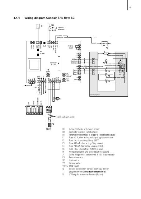
4.4.4 Wiring diagram Condair SH2 flow SC<br />
-<br />
Y<br />
+<br />
B1<br />
B4<br />
Clean Trg. 1:<br />
e.Demand<br />
brown<br />
white<br />
brown<br />
white<br />
P<br />
GND<br />
0-10V<br />
N<br />
P1<br />
GND<br />
Input+<br />
5V/24V<br />
F4<br />
200mAF<br />
L1 N L1 N<br />
24V<br />
5V<br />
+24V<br />
F1<br />
6.3AT<br />
Res1<br />
Res2<br />
Level max<br />
level min / PS<br />
Connector<br />
to CPU<br />
+24V<br />
L1<br />
N<br />
SC<br />
SC<br />
PT1<br />
PT2<br />
F3<br />
630mAT<br />
F2<br />
1AT<br />
Reserve<br />
Output<br />
N<br />
UV Lamp N<br />
Drain Valve<br />
Inlet Valve<br />
N<br />
Stage 3<br />
Stage 2<br />
Stage 1<br />
N<br />
Pump<br />
7<br />
6<br />
5<br />
PE<br />
4 (N)<br />
3<br />
2<br />
1<br />
brown<br />
PS<br />
V<br />
Y2<br />
Y5<br />
Y4<br />
Y3<br />
blue<br />
N<br />
Modul B<br />
S2<br />
1<br />
4<br />
Front panel<br />
J<br />
2<br />
5<br />
Connecting box<br />
H<br />
Error<br />
Service<br />
Humidification<br />
Unit On<br />
L1 N<br />
B2<br />
Q<br />
cross section 1.5 mm 2<br />
F6<br />
PE L1 N<br />
B1 Active controller or humidity sensor<br />
B2 Ventilator interlock (safety chain)<br />
B4 Potential free contact, to trigger a “Box cleaning cycle”<br />
F1 Fuse 6.3 A, slow acting (Voltage supply control unit)<br />
F2 Fuse 1 A, slow acting (Relay 230 V)<br />
F3 Fuse 630 mA, slow acting (Step valves)<br />
F4 Fuse 200 mA, fast acting (Analog entry)<br />
F6 Fuse 10 A, slow acting (Voltage supply)<br />
H Remote operating and fault indication (Option)<br />
J Cable bridge (must be removed, if “B2” is connected)<br />
PS Pressure switch<br />
S2 Unit switch<br />
Y2 Rinsing valve<br />
Y3-Y5 Step valves<br />
Q Service switch (min. contact opening 3 mm) or<br />
plug connection (installation mandatory)<br />
V UV lamp for water sterilisation (Option)