Vehicle Crashworthiness and Occupant Protection - Chapter 3
Vehicle Crashworthiness and Occupant Protection - Chapter 3
Vehicle Crashworthiness and Occupant Protection - Chapter 3

Create successful ePaper yourself
Turn your PDF publications into a flip-book with our unique Google optimized e-Paper software.
<strong>Vehicle</strong> <strong>Crashworthiness</strong> <strong>and</strong> <strong>Occupant</strong> <strong>Protection</strong><br />
models with rigid or deformable barriers with 40 to 50 percent overlap, vehicle-tovehicle<br />
impact with full or partial overlap, <strong>and</strong> central or off-center impacts with a<br />
rigid pole.<br />
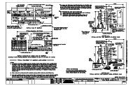
The following example illustrates the development of a frontal crash model of a<br />
four-door passenger car. It simulates the primary load carrying components of<br />
the vehicle in frontal impact with a rigid barrier. Particular attention was paid to<br />
the FE mesh of the mid-rails, lateral rails, front tie bar, <strong>and</strong> dash panel. All sheet<br />
metal components were modeled <strong>and</strong> fastened together by spot welds<br />
corresponding to the actual hardware. Approximately 10 mm x 10 mm shell elements<br />
were used in the front structure where plastic hinges <strong>and</strong> buckling were anticipated.<br />
Coarser mesh was used for the structure behind the dash panel where limited<br />
deformations were expected. The model included a bumper system with<br />
appropriate connectivity to the mid-rails. The radiator was modeled using solid<br />
elements, with material properties corresponding to honeycomb behavior in<br />
compression. The engine <strong>and</strong> transmission were simulated by rigid shell elements,<br />
which represented the mass <strong>and</strong> moments of inertia at the engine’s CG location.<br />
The engine mounts between the engine <strong>and</strong> the supporting structure were modeled<br />
by appropriate joints. The tires <strong>and</strong> wheels were modeled by a combination of<br />
shell <strong>and</strong> solid elements to represent the compliance <strong>and</strong> load transmission<br />
characteristics of these components. Two front door models were included with<br />
appropriate hinge properties. The rear doors were excluded, as their influence on<br />
frontal crash performance was assumed negligible. An instrument panel was also<br />
included along with appropriate structures for knee restraint. Finally, the inertial<br />
characteristics of the whole vehicle model were checked against the actual vehicle<br />
<strong>and</strong> concentrated masses were added to ensure agreement between the model’s<br />
inertia <strong>and</strong> the corresponding hardware.<br />
3.6.3.1 Model Statistics:<br />
• 61,500 shell elements<br />
• 500 solid elements<br />
• 25 beam elements<br />
• 1,200 spot welds<br />
• 15 joints<br />
• 40 concentrated nodal masses<br />
• 10 springs<br />
• 200 parts<br />
• 66,000 nodes<br />
Page 142