
You also want an ePaper? Increase the reach of your titles
YUMPU automatically turns print PDFs into web optimized ePapers that Google loves.
4.Connect the siren's BLACK wire to the third mounting screw, using the spade connector. Make sure this<br />
is a solid ground.<br />
5.Connect the siren's RED wire to the module's GREY wire.<br />
FINDING CONSTANT AND IGNITION POWER<br />
Your system requires 12 volts constant and ignition 12 volt that is only on when the ignition is on.<br />
1.There is usually a large gauge wire going to your ignition switch. Probe this wire. Confirm that the<br />
light comes on or the meter indicates 12 volts. This wire will show positive voltage in all key positions.<br />
2.Connect the RED wire from the harness to this wire.<br />
3.Connect the BLACK wire from the harness to a clean chassis ground using the spade terminal. TEST: Press<br />
transmitter Button #1 and the siren should chirp once. Wait 5 seconds, then press transmitter Button<br />
#1 again, and the siren should chirp twice.<br />
4.Probe for a wire that has 12 volts only when the ignition is on. Confirm this by turning the ignition<br />
switch on and off while probing each wire, this wire will not show 12 volts with the key off.<br />
5.Connect the RED WITH BLACK STRIPE wire to this wire. TEST: Turn the ignition switch to the ON position<br />
and then press transmitter Button #1, the system should not arm. If it does, you are not connected to<br />
the ignition wire.<br />
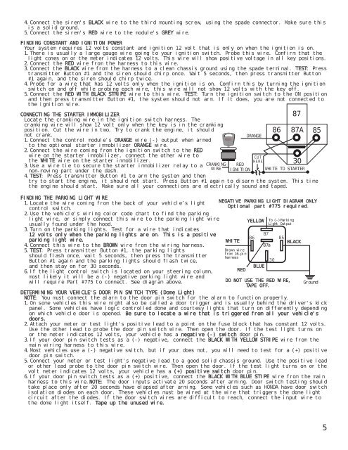
CONNECTING THE STARTER IMMOBILIZER<br />
Locate the cranking wire in the ignition switch harness. The<br />
cranking wire will show 12 volt only when the key is in the cranking<br />
position. Cut the wire in two. Try to crank the engine, it should<br />
not crank.<br />
1.Connect the control module’s ORANGE wire (-) output when armed<br />
to the optional starter immobilizer ORANGE wire.<br />
2.Connect the wire coming from the ignition switch to the RED<br />
wire on the starter immobilizer, connect the other wire to<br />
the WHITE wire on the starter immobilizer.<br />
3.Use a wire tie to secure the starter immobilizer relay to a<br />
non-moving part under the dash.<br />
4.TEST: Press transmitter Button #1 to arm the system and then<br />
CRANKING<br />
WIRE<br />
87A 85<br />
try to start the engine, it should not start. Press Button #1 again to disarm the system. This time<br />
the engine should start. Make sure all your connections are electrically sound and taped.<br />
FINDING THE PARKING LIGHT WIRE<br />
1.Locate the wire coming from the back of your vehicle’s light<br />
control switch.<br />
2.Use the vehicle's wiring color code chart to find the parking<br />
light wire, or simply connect this wire to the parking light wire<br />
usually found under the hood.<br />
3.Turn on the parking lights. Test for a wire that indicates<br />
12 volts only when the parking lights are on. This is a positive<br />
parking light wire.<br />
4.Connect this wire to the BROWN wire from the wiring harness.<br />
5.TEST: Press transmitter Button #1, the parking lights<br />
should flash once, wait 5 seconds, then press the transmitter<br />
Button #1 again and the parking lights should flash twice,<br />
and then stay on for 30 seconds.<br />
6.If the light control switch is located on your steering column,<br />
most likely it will be a (-) negative parking light wire and<br />
will require Part #775 to connect. See diagram above.<br />
RED<br />
IGNITION<br />
ORANGE<br />
86<br />
87<br />
30<br />
WHITE TO STARTER<br />
NEGATIVE PARKING LIGHT DIAGRAM ONLY<br />
Optional part #775 required.<br />
DO NOT USE THE RED WIRE,<br />
TAPE OFF.<br />
DETERMINING YOUR VEHICLE'S DOOR PIN SWITCH TYPE (Dome Light)<br />
NOTE: You must connect the alarm to the door pin switch for the alarm to function properly.<br />
1.On some vehicles this wire might also be called a door trigger and is usually behind the driver's kick<br />
panel. Some vehicles have logic controlled dome and courtesy lights that turn on differently depending<br />
on which vehicle door is opened. Be sure to locate a wire that is triggered from all your vehicle's<br />
doors.<br />
2.Attach your meter or test light's positive lead to a point on the fuse block that has constant 12 volts.<br />
Use the other lead to probe the door pin switch wire. Then open the door. If the test light turns on<br />
or the meter indicates 12 volts, your vehicle has a negative (-) switch door pin.<br />
3.If your door pin switch tests as a (-) negative, connect the BLACK WITH YELLOW STRIPE wire from the<br />
main wiring harness to this wire.<br />
4.Most vehicles use a (-) negative switch, but if your does not, you will need to test for a (+) positive<br />
door pin switch.<br />
5.Connect your meter or test light's negative lead to a good solid chassis ground. Use the positive lead<br />
or other lead probe to the door pin switch wire. Then open the door. If the test light turns on or the<br />
volt meter indicates 12 volts, your vehicle has a (+) positive switch door pin.<br />
6.If your door pin switch tests as a (+) positive, connect the BLACK WITH BLUE STIPE wire from the main<br />
harness to this wire.NOTE: The door inputs activate 20 seconds after arming. Door switch testing should<br />
take place only after 20 seconds have elapsed after arming. Some vehicles such as HONDA have door switch<br />
isolation diodes on each door. These vehicles must be wired at the wire that triggers the dome light<br />
circuit after the diodes. If the door switch wires are difficult to reach, connect the input wire to<br />
the dome light itself. Tape up the unused wire.<br />
WHITE<br />
Brown wire<br />
from 16-pin<br />
harness<br />
RED<br />
YELLOW<br />
BLUE<br />
87a<br />
To (-)Parking<br />
Light Output<br />
BLACK<br />
Ground<br />
5