
Create successful ePaper yourself
Turn your PDF publications into a flip-book with our unique Google optimized e-Paper software.
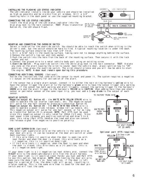
INSTALLING THE FLASHING LED STATUS INDICATOR<br />
The LED indicator installs inside your vehicle and should be installed<br />
as high as possible and be visible from all windows. Drill a 1/4"<br />
mounting hole in the dash panel or use the supplied mounting bracket.<br />
CONNECTING THE LED STATUS INDICATOR<br />
Insert the blue plug of the LED status indicator into the<br />
blue plug next to the main connector. TEST: Press transmitter<br />
Button #1, the LED should flash.<br />
WHITE PLUG<br />
ON THE LEFT<br />
OF MODULE<br />
:<br />
BLUE PLUG<br />
:<br />
MAIN CONNECTOR<br />
OVERRIDE<br />
SWITCH<br />
ANTI-CARJACKING<br />
SWITCH<br />
LED<br />
INDICATOR<br />
MOUNTING AND CONNECTING THE OVERRIDE SWITCH<br />
Select a location for the override switch. You should be able to reach the switch when sitting in the<br />
driver's seat, but the switch should be hard to find. A typical mounting location is under the dash.<br />
The mounting surface should be less than 1/8" thick.<br />
1.Drill a 5/16" hole in the mounting surface, taking care not to damage anything behind the surface.<br />
2.Remove the switch's top nut and lock washer.<br />
3.Push the switch into the hole from the back of the mounting surface. Then secure it with the lock<br />
washer and nut.<br />
4.Connect the ground wire to a metal vehicle body part using an existing screw.<br />
5.Override Switch - Plug override switch into the white plug next to the main connector. TEST: Violate<br />
any zone on the alarm causing the siren to sound. Open the vehicle door, place ignition key to "ON"<br />
position, then press the override switch. The siren should silence and you will now be able to start<br />
the engine. NOTE: A door must remain open during this procedure.<br />
CONNECTING ADDITIONAL SENSORS (Optional)<br />
Follow the instructions that come with the sensor to mount and power it. The system requires a negative<br />
(-) output on the accessory for activation of the alarm.<br />
If the sensor has a single alarm output, connect it to either the main wiring harness's yellow wire to<br />
have the sensor trigger the alarm or to the harness's green wire to have the sensor trigger only warning<br />
chirps. If the sensor has both warning and alert triggers, connect the warning trigger to the harness's<br />
GREEN wire and the alert trigger to the harness's YELLOW wire CAUTION: When adding more than one shock<br />
sensor or perimeter sensor on the same input trip, you must add a 1 amp diode to the output of each<br />
sensor.<br />
NEGATIVE OUTPUTS<br />
Negative output #2, Button #2 - the WHITE WITH YELLOW STRIPE wire is<br />
used to operate the car starter (optional), etc. The negative output<br />
will pulse for one half second by pressing transmitter Button #2.<br />
Negative output #3, Button #3 - the WHITE WITH RED STRIPE wire is<br />
used to operate a power trunk release, window roll-up module, etc.<br />
This negative output will pulse for one half second, or for as long<br />
as transmitter Button #3 is pressed. NOTE: Part #775 must be used<br />
since this negative output is only rated for 200mA (1/5 amp). Since<br />
most power trunk releases are positive controlled and draw 5 to 6<br />
amps, this relay (Part #775) handles the load and also can convert<br />
the release signal from negative to positive polarity.<br />
GROUND<br />
TO FACTORY TRUNK WIRE<br />
WHITE/RED<br />
FROM<br />
ALARM<br />
87a<br />
DOME LIGHT SUPERVISION (Optional)<br />
The dome light supervision wire on the vehicle is the same wire as<br />
your door pin wire. It can be located at the door pin switch or under<br />
dash courtesy lights.<br />
• If this wire tests (+) positive when the door is open (as with<br />
most Fords) and when the door is closed, this wire tests as a<br />
(-) negative, this is (+) positive dome light.<br />
• If this wire tests (-) negative, when the door is open and when<br />
the door is closed, this wire tests as a (+) positive, this is<br />
a (-) negative dome light.<br />
If your dome light is a (-) negative (as most others are), connect the<br />
VIOLET wire to the domelight/doorpin wire from the 16-pin harness.<br />
If your dome light is (+) positive (most Fords) you must add Part #775<br />
to use this option. See diagram. NOTE: When testing the door pin wire,<br />
make sure the dome light is on. Some vehicles, if the door is left<br />
open for a period of time, the dome light will go out, resulting in<br />
a false reading. This is the same wire that is used for the door pin<br />
switch and will test the same.<br />
WHITE<br />
Optional part #775 required.<br />
To Dome Light<br />
YELLOW Circuit<br />
(-) VIOLET<br />
FROM 16-pin<br />
wire harness.<br />
RED<br />
DO NOT USE,<br />
TAPE OFF.<br />
+12 VOLT FUSED<br />
AT 20 AMPS<br />
87a<br />
BLACK<br />
BLUE<br />
+12 VOLT FUSED<br />
AT 5 AMPS<br />
6