Modeling of Lithium-Ion Battery for Energy Storage System Simulation
Modeling of Lithium-Ion Battery for Energy Storage System Simulation
Modeling of Lithium-Ion Battery for Energy Storage System Simulation

You also want an ePaper? Increase the reach of your titles
YUMPU automatically turns print PDFs into web optimized ePapers that Google loves.
then explained in terms <strong>of</strong> the battery SOD in a n th order<br />
polynomial. Also, from Fig. 1, the equilibrium potential<br />
E(t,T,i,l) is also seen as a function <strong>of</strong> V(i,T,t,l) and current i(t).<br />
These relationships are expressed as (1) and (2).<br />
2) Secondly, the discharge rate and temperature corresponding<br />
to the reference curve are treated as the reference discharge<br />
rate and temperature.<br />
There<strong>for</strong>e in view <strong>of</strong> the above, expressions <strong>for</strong> E, V(i,T,t,l),<br />
SOD and Rint are<br />
Eit [ ( ), T( t), tl , ] = vit [ ( ), T( t), tl , ] + R i( t)<br />
(1)<br />
n<br />
�<br />
int r<br />
v[ i( t), T( t), t, l] = c SOD [ i( t), T( t), t, l]<br />
(2)<br />
k<br />
k = 0<br />
k<br />
t<br />
1<br />
SOD[(), i t T (), t t, l] = � i() t dt<br />
(3)<br />
Q 0<br />
R = R + R<br />
(4)<br />
int 1 2<br />
Where ck is the coefficient <strong>of</strong> the k th -order term in the<br />
polynomial representation <strong>of</strong> the reference curve and Qr is the<br />
battery capacity referred to the cut<strong>of</strong>f voltage <strong>for</strong> the reference<br />
curve. For k = 0, E = c0 is the open-circuit voltage at the<br />
beginning <strong>of</strong> discharge at the reference temperature <strong>of</strong> the<br />
reference curve.<br />
B. Description <strong>of</strong> the Internal Resistance<br />
Normally, the internal resistance Rint will increase with the<br />
state <strong>of</strong> discharge. In this model, Rint has two components R1<br />
and R2. R1 is defined as the internal resistance <strong>of</strong> the lithiumion<br />
battery at SOD=0. It depends on the discharge condition,<br />
i.e. temperature, current level and lifecycle. R2 is the increase<br />
in Rint as SOD increases. R2 can also be affected by the<br />
temperature. However, it is proposed that an n th -order<br />
polynomial is used instead to describe the relationship<br />
between R2 and SOD. A correction factor �(T) will then be<br />
used later to compensate <strong>for</strong> variation <strong>of</strong> R2 with T.<br />
Based on the above, R can be defined as a function <strong>of</strong><br />
1<br />
discharge current, temperature and lifecycle, as follows,<br />
R = f( i( t), T( t), l)<br />
(5)<br />
1<br />
Take derivative on both sides <strong>of</strong> (5),<br />
δ f δ f δ f<br />
∂ R = ∂ i+ ∂ T + ∂l<br />
(6)<br />
1<br />
δi δT δl<br />
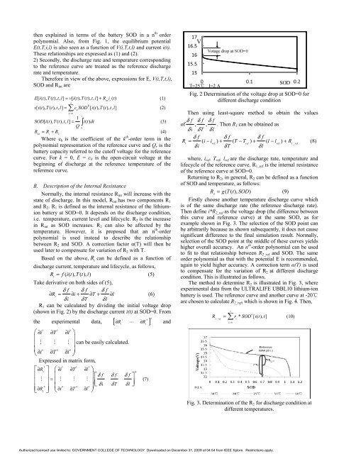
R1 can be calculated by dividing the initial voltage drop<br />
(shown in Fig. 2) by the discharge current i(t) at SOD=0. From<br />
T<br />
1 n<br />
the experimental data, [ ∂R ∂R<br />
]<br />
1 1<br />
1 1 1<br />
�∂i ∂T ∂l<br />
�<br />
�<br />
�<br />
�<br />
� n<br />
�∂i �<br />
n<br />
∂T �<br />
� can be easily calculated.<br />
�<br />
n<br />
∂l<br />
�<br />
�<br />
Expressed in matrix <strong>for</strong>m,<br />
1 1<br />
�∂R � �∂i � � �<br />
� = �<br />
� � �<br />
n<br />
n<br />
�∂R �<br />
� � i 1 � �∂ 1<br />
∂T �<br />
n<br />
∂T 1<br />
∂l<br />
�<br />
��δ<br />
f<br />
�<br />
���<br />
δi n<br />
∂l<br />
�<br />
�<br />
δ f<br />
δT δ f �<br />
δl<br />
��<br />
1 T<br />
� and<br />
(7)<br />
17<br />
V<br />
16.5<br />
16<br />
15.5<br />
15<br />
0 0.1 0.2<br />
SOD<br />
T=25� I=2 A<br />
Fig. 2 Determination <strong>of</strong> the voltage drop at SOD=0 <strong>for</strong><br />
different discharge condition<br />
Then using least-square method to obtain the values<br />
δ f δ f δ f<br />
<strong>of</strong> , ,<br />
δiδT δ l<br />
. Then R1 can be obtained as<br />
δ f δ f δ f<br />
R = ( i− i ) + ( T − T ) + ( l − l ) + R (8)<br />
1 ref ref ref 1_ref<br />
δi δT δl<br />
where, iref, Tref, lref are the discharge rate, temperature and<br />
lifecycle <strong>of</strong> the reference curve. R1_ref is the internal resistance<br />
<strong>of</strong> the reference curve at SOD=0.<br />
Returning to R2, in general, R2 can be defined as a function<br />
<strong>of</strong> SOD and temperature, as follows:<br />
R = g( T( t), SOD)<br />
(9)<br />
2<br />
Firstly choose another temperature discharge curve which<br />
is <strong>of</strong> the same discharge rate (the reference discharge rate).<br />
Then define i*R2_ref as the voltage drop (the difference between<br />
this curve and reference curve) at the same SOD, as <strong>for</strong><br />
example shown in Fig. 3. The selection <strong>of</strong> the SOD point can<br />
be arbitrarily because as shown subsequently, it does not cause<br />
significant difference to the final simulation result. Normally,<br />
selection <strong>of</strong> the SOD point at the middle <strong>of</strong> these curves yields<br />
higher overall accuracy. An n th -order polynomial can be used<br />
to fit to that relationship between R2_ref and SOD. The same<br />
order polynomial as that with the potential E is recommended,<br />
again to yield higher accuracy. A correction term �(T) is used<br />
to compensate <strong>for</strong> the variation <strong>of</strong> R2 at different discharge<br />
condition. This is illustrated as follows.<br />
The method to determine R2 is illustrated in Fig. 3, where<br />
experimental data from the ULTRALIFE UBBL10 lithium-ion<br />
battery is used. The reference curve and another curve at -20�<br />
are chosen to calculate R2_ref, which is shown in Fig. 4. Then,<br />
n<br />
k<br />
R = � r * SOD [ i( t), t]<br />
(10)<br />
2_ref<br />
k<br />
k = 0<br />
Fig. 3. Determination <strong>of</strong> the R2 <strong>for</strong> discharge condition at<br />
different temperatures.<br />
Authorized licensed use limited to: GOVERNMENT COLLEGE OF TECHNOLOGY. Downloaded on December 31, 2009 at 04:54 from IEEE Xplore. Restrictions apply.