A-dec 500 12 O'Clock System
A-dec 500 12 O'Clock System
A-dec 500 12 O'Clock System
- No tags were found...

Create successful ePaper yourself
Turn your PDF publications into a flip-book with our unique Google optimized e-Paper software.
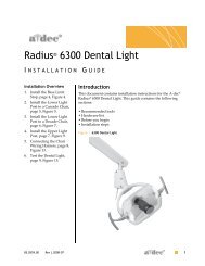
A-<strong>dec</strong> <strong>500</strong> <strong>12</strong> O’Clock <strong>System</strong> Installation Guide<br />
8. Wire the delivery system:<br />
(1) Connect all data lines from the<br />
delivery system. Use the data<br />
connector provided.<br />
CAUTION Circuit boards are<br />
sensitive to static electricity.<br />
Electrostatic Discharge (ESD)<br />
precautions are required when<br />
touching a circuit board or making<br />
connections to or from the circuit<br />
board. Circuit boards should be<br />
installed only by an electrician or<br />
qualified service person.<br />
(2) Connect the low-voltage power cables<br />
to the power supply.<br />
Install Ancillary Equipment<br />
Install any ancillary equipment (such as a<br />
curing light, etc.) for the A-<strong>dec</strong> <strong>500</strong><br />
<strong>12</strong> o’clock system. Use the instructions<br />
provided with the modules.<br />
Attach and Level<br />
Round Worksurface<br />
1. If necessary, remove the screws from the<br />
threaded standoffs in the metal plate<br />
underneath the worksurface. See<br />
Figure 16.<br />
2. Position the round worksurface on the<br />
worksurface support housing. Align the<br />
screw holes in the worksurface support<br />
housing with the threaded standoffs in<br />
the metal plate on the bottom of the<br />
worksurface.<br />
3. Insert the first set of worksurface screws<br />
and tighten until secure. Use two of the<br />
screws removed in Step 1 and a 1/8" hex<br />
key.<br />
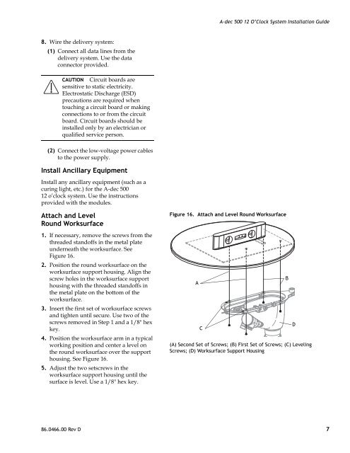
4. Position the worksurface arm in a typical<br />
working position and center a level on<br />
the round worksurface over the support<br />
housing. See Figure 16.<br />
5. Adjust the two setscrews in the<br />
worksurface support housing until the<br />
surface is level. Use a 1/8" hex key.<br />
Figure 16. Attach and Level Round Worksurface<br />
A<br />
C<br />
(A) Second Set of Screws; (B) First Set of Screws; (C) Leveling<br />
Screws; (D) Worksurface Support Housing<br />
B<br />
D<br />
86.0466.00 Rev D 7