Condensed Catalog Featuring R410A Products Third Edition
Condensed Catalog Featuring R410A Products Third Edition
Condensed Catalog Featuring R410A Products Third Edition

You also want an ePaper? Increase the reach of your titles
YUMPU automatically turns print PDFs into web optimized ePapers that Google loves.
Technical leaflet<br />
Pressure Controls, type KPU<br />
Design and function<br />
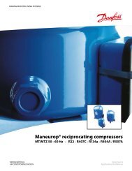
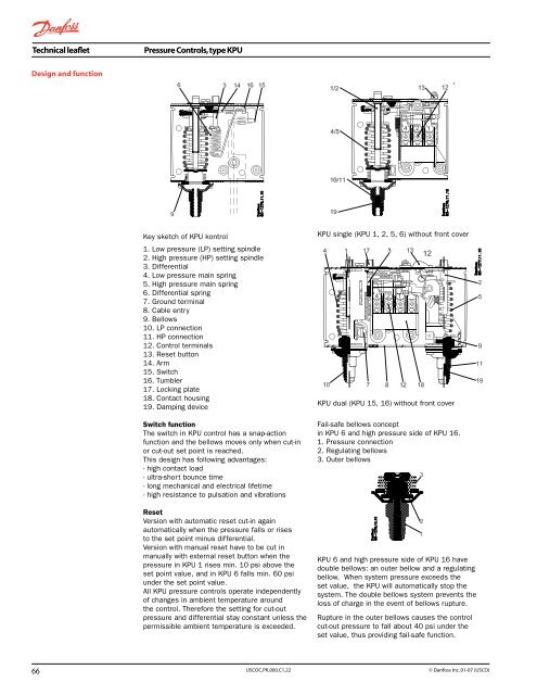
Key sketch of KPU kontrol<br />
1. Low pressure (LP) setting spindle<br />
2. High pressure (HP) setting spindle<br />
3. Differential<br />
4. Low pressure main spring<br />
5. High pressure main spring<br />
6. Differential spring<br />
7. Ground terminal<br />
8. Cable entry<br />
9. Bellows<br />
10. LP connection<br />
11. HP connection<br />
12. Control terminals<br />
13. Reset button<br />
14. Arm<br />
15. Switch<br />
16. Tumbler<br />
17. Locking plate<br />
18. Contact housing<br />
19. Damping device<br />
Switch function<br />
The switch in KPU control has a snap-action<br />
function and the bellows moves only when cut-in<br />
or cut-out set point is reached.<br />
This design has following advantages:<br />
- high contact load<br />
- ultra-short bounce time<br />
- long mechanical and electrical lifetime<br />
- high resistance to pulsation and vibrations<br />
Reset<br />
Version with automatic reset cut-in again<br />
automatically when the pressure falls or rises<br />
to the set point minus differential.<br />
Version with manual reset have to be cut in<br />
manually with external reset button when the<br />
pressure in KPU 1 rises min. 10 psi above the<br />
set point value, and in KPU 6 falls min. 60 psi<br />
under the set point value.<br />
All KPU pressure controls operate independently<br />
of changes in ambient temperature around<br />
the control. Therefore the setting for cut-out<br />
pressure and differential stay constant unless the<br />
permissible ambient temperature is exceeded.<br />
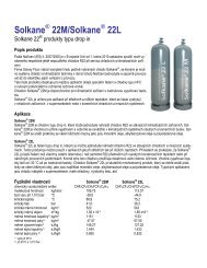
KPU single (KPU 1, 2, 5, 6) without front cover<br />
KPU dual (KPU 15, 16) without front cover<br />
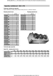
Fail-safe bellows concept<br />
in KPU 6 and high pressure side of KPU 16.<br />
1. Pressure connection<br />
2. Regulating bellows<br />
3. Outer bellows<br />
KPU 6 and high pressure side of KPU 16 have<br />
double bellows: an outer bellow and a regulating<br />
bellow. When system pressure exceeds the<br />
set value, the KPU will automatically stop the<br />
system. The double bellows system prevents the<br />
loss of charge in the event of bellows rupture.<br />
Rupture in the outer bellows causes the control<br />
cut-out pressure to fall about 40 psi under the<br />
set value, thus providing fail-safe function.<br />
66 USCOC.PK.000.C1.22 © Danfoss Inc. 01-07 (USCO)