

New Models Simulate RF Circuits - Intusoft
New Models Simulate RF Circuits - Intusoft
New Models Simulate RF Circuits - Intusoft

Create successful ePaper yourself
Turn your PDF publications into a flip-book with our unique Google optimized e-Paper software.
Modeling An <strong>RF</strong> Bead<br />
Although SPICE does contain a model for a nonlinear inductor it<br />
does not have a built-in bead model. Fortunately, one can be<br />
created using the a nonlinear magnetics model and passive<br />
elements. The new model, as shown in Figures 1 & 2, accurately<br />
simulates the impedance vs. frequency response and the change<br />
in impedance vs. temperature. The change in impedance with DC<br />
bias is also modeled due to the addition of the core model instead<br />
of a simple inductor. The bead model gives a very low DC<br />
impedance while providing a large impedance at higher frequencies.<br />
The model used here is for a ferrite bead made of a medium<br />
permeability nickel zinc material from Fair-Rite, P#2743009112.<br />
Other types of beads including beads on leads, wound beads and<br />
surface mount beads can be found in the <strong>RF</strong> library [2].<br />
180<br />
180<br />
1<br />
Z (2743003112) in Ohms<br />
140<br />
100.0<br />
60.0<br />
Z (2743009112) in Ohms<br />
140<br />
100.0<br />
60.0<br />
2<br />
3<br />
4<br />
20.0<br />
20.0<br />
1MEG 10MEG 100MEG 1G<br />
Impedance (Ohms) vs. Frequency in Hz<br />
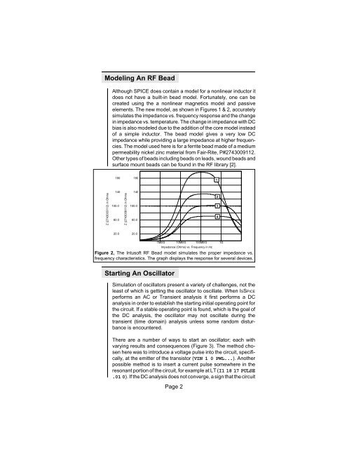
Figure 2, The <strong>Intusoft</strong> <strong>RF</strong> Bead model simulates the proper impedance vs.<br />
frequency characteristics. The graph displays the response for several devices.<br />
Starting An Oscillator<br />
Simulation of oscillators present a variety of challenges, not the<br />
least of which is getting the oscillator to oscillate. When ISSPICE<br />
performs an AC or Transient analysis it first performs a DC<br />
analysis in order to establish the starting initial operating point for<br />
the circuit. If a stable operating point is found, which is the goal of<br />
the DC analysis, the oscillator may not oscillate during the<br />
transient (time domain) analysis unless some random disturbance<br />
is encountered.<br />
There are a number of ways to start an oscillator; each with<br />
varying results and consequences (Figure 3). The method chosen<br />
here was to introduce a voltage pulse into the circuit, specifically,<br />
at the emitter of the transistor (VIN 1 0 PWL...). Another<br />
possible method is to insert a current pulse somewhere in the<br />
resonant portion of the circuit, for example at LT (I1 18 17 PULSE<br />
.01 0). If the DC analysis does not converge, a sign that the circuit<br />
Page 2


