

New Models Simulate RF Circuits - Intusoft
New Models Simulate RF Circuits - Intusoft
New Models Simulate RF Circuits - Intusoft

You also want an ePaper? Increase the reach of your titles
YUMPU automatically turns print PDFs into web optimized ePapers that Google loves.
When simulating in SPICE it is best to use a subcircuit representation<br />
for a device rather than forcing model parameters to have<br />
unreasonable values. If model parameters are used outside their<br />
physical bounds, the model may work well in one area, but<br />
incorrectly in another. For example, the device may behave<br />
properly during the AC small signal analysis, but poorly during the<br />
nonlinear transient analysis. Some vendors who produce SPICE<br />
model use this approach and the user should beware. <strong>Models</strong> for<br />
<strong>RF</strong> transistors that are going to be used for both linear and<br />
nonlinear analysis can not be produced this way. A subcircuit<br />
representation must be used!<br />
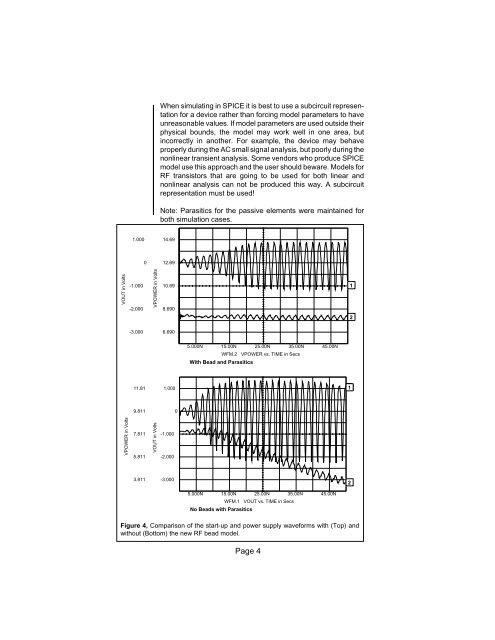
Note: Parasitics for the passive elements were maintained for<br />
both simulation cases.<br />
1.000<br />
14.69<br />
0<br />
12.69<br />
VOUT in Volts<br />
-1.000<br />
-2.000<br />
VPOWER in Volts<br />
10.69<br />
8.690<br />
1<br />
2<br />
-3.000<br />
6.690<br />
5.000N 15.00N 25.00N 35.00N 45.00N<br />
WFM.2 VPOWER vs. TIME in Secs<br />
With Bead and Parasitics<br />
11.81<br />
1.000<br />
1<br />
9.811<br />
0<br />
VPOWER in Volts<br />
7.811<br />
5.811<br />
VOUT in Volts<br />
-1.000<br />
-2.000<br />
3.811<br />
-3.000<br />
2<br />
5.000N 15.00N 25.00N 35.00N 45.00N<br />
WFM.1 VOUT vs. TIME in Secs<br />
No Beads with Parasitics<br />
Figure 4, Comparison of the start-up and power supply waveforms with (Top) and<br />
without (Bottom) the new <strong>RF</strong> bead model.<br />
Page 4


