High Performance Solar Cells Exceeding 17 ... - ISC Konstanz
High Performance Solar Cells Exceeding 17 ... - ISC Konstanz
High Performance Solar Cells Exceeding 17 ... - ISC Konstanz

You also want an ePaper? Increase the reach of your titles
YUMPU automatically turns print PDFs into web optimized ePapers that Google loves.
Average solar cell efficiency [%]<br />
Lifetime [s]<br />
texturisation all samples were processed by POCl 3<br />
diffusion, PECVD SiN x deposition, full Al BSF screen<br />
printing, Ag finger grid screen printing and firing<br />
through. Measurements of the solar cell parameters were<br />
carried out and the reverse current was determined at<br />
-14.5V to see the influence of the texturisation on both<br />
results.<br />
3 RESULTS<br />
3.1 Results of diffusion optimization<br />
Minority carrier lifetime measurements were<br />
performed to screen the feedstock quality of the<br />
investigated ingots. Therefore the saw damage of wafers<br />
from the center bricks of each ingot was removed and the<br />
samples were passivated by a PECVD SiN x . The<br />
lifetimes of those samples were determined using QSSPC<br />
measurements and are shown in figure 1.<br />
60<br />
50<br />
40<br />
30<br />
20<br />
10<br />
0<br />
ESS 1<br />
ESS 2<br />
ESS 3<br />
Poly<br />
0 10 20 30 40 50 60 70 80 90 100<br />
Ingot Height [%]<br />
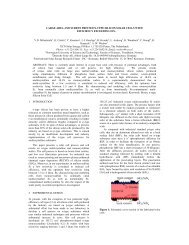
Figure 1: Minority carrier lifetime of wafers from<br />
different ingot positions, measured by QSSPC. Ingots<br />
ESS 1 and 2 were purified by IMCC and thus are not<br />
made from the standard ESS feedstock.<br />
Lifetimes between 10µs and 60µs have been measured on<br />
both ESS and poly-Si wafers. Figure 1 shows that the<br />
minority carrier lifetime of the ESS based wafers is at<br />
least on the same level or even higher compared to the<br />
poly-Si reference wafers. The bottom wafers of both<br />
ingots ESS 3 and poly show reduced lifetimes most<br />
likely due to some crucible induced impurities. For the<br />
highest wafer positions the lifetime of all four ingots is<br />
decreasing. In case of the poly-Si ingot it is likely that the<br />
higher boron doping at the top, because of the<br />
segregation of impurities is a reason for the decrease in<br />
lifetime. For the ESS based samples dislocations,<br />
found at the higher ingot positions, might limit the carrier<br />
lifetime, because they act as active recombination<br />
centers.<br />
and are thus not made from standard ESS feedstock<br />
Ingot Brick<br />
V oc<br />
[mv]<br />
J sc<br />
[mA/cm²]<br />
FF<br />
[%]<br />
η<br />
[%]<br />
ESS 1 Corner 621.9 33.7 79.5 16.7<br />
ESS 1 Center 618.4 33.5 79.7 16.5<br />
ESS 2 Corner 619.1 33.9 79.3 16.6<br />
ESS 2 Center 616.8 33.8 79.1 16.5<br />
ESS 3 Corner 613.6 33.5 79.1 16.3<br />
ESS 3 Center 618.7 33.9 79.3 16.6<br />
poly Corner 615.1 33.7 79.0 16.4<br />
poly Center 6<strong>17</strong>.1 33.9 79.2 16.6<br />
Table II: Average solar cell parameters over at least 18<br />
cells per brick, which were evenly distributed over the<br />
complete ingot height, processed using an optimized<br />
diffusion regarding more efficient gettering. Ingots ESS 1<br />
and ESS 2 have been grown using IMCC technology as a<br />
previous step of purification and are thus not made from<br />
standard ESS feedstock.<br />
Ingot Brick<br />
V oc<br />
[mv]<br />
J sc<br />
[mA/cm²]<br />
FF<br />
[%]<br />
η<br />
[%]<br />
ESS 1 Corner 623.8 33.8 79.5 16.7<br />
ESS 1 Center 620.2 33.6 79.6 16.6<br />
ESS 2 Corner 620.5 33.9 79.2 16.7<br />
ESS 2 Center 618.4 33.9 79.0 16.6<br />
ESS 3 Corner 614.5 33.5 78.9 16.3<br />
ESS 3 Center 619.8 34.0 79.2 16.7<br />
poly Corner 616.2 33.8 78.9 16.4<br />
poly Center 618.5 34.0 79.2 16.6<br />
The ingots ESS 1 and ESS 2, which were purified using<br />
IMCC technology, show the highest achieved solar cell<br />
efficiencies, due to high FF, because of the low resistivity<br />
and thus a low series resistance, high V oc caused by the<br />
Fermi level shift as a result of the higher boron<br />
concentration and respective higher doping levels [6],<br />
and J sc similar to the reference wafers. Ingot ESS 3<br />
also shows a good performance at the centre brick,<br />
whereas the corner brick shows the lowest average<br />
efficiency of all investigated bricks.<br />
<strong>17</strong>,0<br />
16,8<br />
16,6<br />
16,4<br />
16,2<br />
Optimized<br />
Standard<br />
IV measurements show average efficiencies, over at<br />
least 18 solar cells from each brick, between 16.3% and<br />
16.7% for the ESS based solar cells and between<br />
16.4% and 16.6% for the poly-Si based solar cell<br />
reference (see table I and II).<br />
Table I: Average solar cell parameters over at least 18<br />
cells per brick, which were evenly distributed over the<br />
complete ingot height, processed using the standard<br />
diffusion. Ingots ESS 1 and ESS 2 have been grown<br />
using IMCC technology as a previous step of purification<br />
16,0<br />
ESS 1 Center<br />
ESS 1 Corner<br />
ESS 2 Center<br />
ESS 2 Corner<br />
ESS 3 Center<br />
ESS 3 Corner<br />
Poly Center<br />
Poly Corner<br />
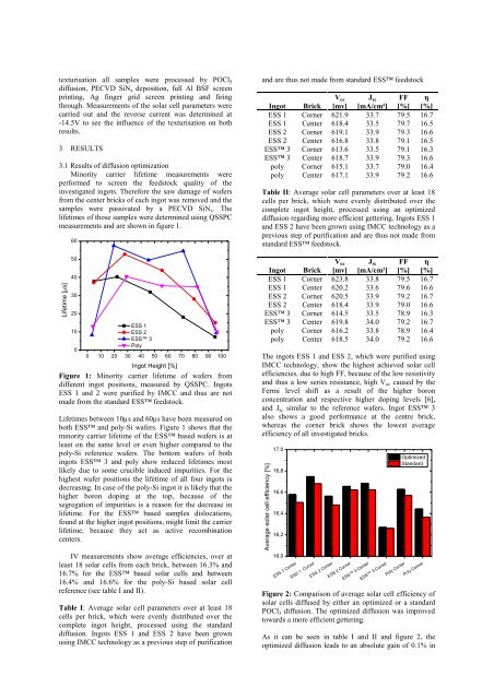
Figure 2: Comparison of average solar cell efficiency of<br />
solar cells diffused by either an optimized or a standard<br />
POCl 3 diffusion. The optimized diffusion was improved<br />
towards a more efficient gettering.<br />
As it can be seen in table I and II and figure 2, the<br />
optimized diffusion leads to an absolute gain of 0.1% in