

nonresident training course - Historic Naval Ships Association
nonresident training course - Historic Naval Ships Association
nonresident training course - Historic Naval Ships Association

Create successful ePaper yourself
Turn your PDF publications into a flip-book with our unique Google optimized e-Paper software.
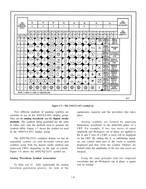
Figure 1-7.—The AN/UYA-4(V) symbol set.<br />
Two different methods of painting symbols are<br />
currently in use in the AN/UYA-4(V) display group.<br />
They are the analog waveform and the digital stroke<br />
methods. The symbols being generated are the same<br />
in either case, only the methods used to generate the<br />
symbols differ. Figure 1-7 shows the symbol set used<br />
in the AN/UYA-4(V) display group.<br />
The AN/UYQ-21(V) computer display set has an<br />
expanded symbol set and develops sweep and<br />
symbols using both the digital stroke method and<br />
raster-scan CRTs, depending on the type of console.<br />
Figure 1-8 shows the AN/UYQ-21(V) symbol set.<br />
Analog Waveform Symbol Generation<br />
To help you to fully understand the analog<br />
waveform generation process, we look at the<br />
equipments required and the procedure that takes<br />
place.<br />
Analog symbols are formed by applying<br />
harmonious waveforms to the deflection plates of a<br />
CRT. For example, if two sine waves of equal<br />
amplitude and 90-degrees out of phase are applied to<br />
the X and Y axes of a CRT, a circle will be displayed<br />
on the CRT. By adding the Z, or unblinking signal,<br />
we can control what part of the circle is actually<br />
displayed and thus form the symbol. Ellipses are<br />
formed when the amplitudes of the two sine waves are<br />
unequal.<br />
Using the same principle with two trapezoid<br />
waveforms that are 90-degrees out of phase, a square<br />
will be formed.<br />
1-8


