

nonresident training course - Historic Naval Ships Association
nonresident training course - Historic Naval Ships Association
nonresident training course - Historic Naval Ships Association

You also want an ePaper? Increase the reach of your titles
YUMPU automatically turns print PDFs into web optimized ePapers that Google loves.
Digital Stroke Symbol Generation<br />
The digital stroke method of symbol generation is<br />
used in some AN/UYA-4(V) display groups that use<br />
the console internally generated and refreshed<br />
symbols (CIGARS) modifications of the digital stroke<br />
symbol generator. The CIGARS modified console<br />
eliminates the need for a separate symbol generator<br />
because each console contains its own symbol<br />
generation circuitry.<br />
of the symbol component. The eight output lines used<br />
to mechanize the symbol are as follows:<br />
Sign X, X, 2X<br />
Sign Y, Y, 2Y<br />
Z (unblank)<br />
W (wait)<br />
The digital stroke symbol generator stores all<br />
symbols as digital codes in a group of read-onlymemory<br />
(ROM) chips or programmable read-onlymemory<br />
(PROM) chips. In this example, we assume<br />
that a PROM is the device that stores the symbol. The<br />
computer sends a message to the display group<br />
indicating what symbol needs to be painted. The<br />
message is translated and the data bits that were used<br />
to identify the symbol in the analog symbol generator<br />
are sent to the stroke control logic and are used to<br />
access stroke codes from a PROM.<br />
There are eight distinct routine states or time<br />
periods in the symbol routine process as shown in<br />
table 1-1. During each routine time, a component of<br />
the symbol to be displayed is mechanized. At the start<br />
of the symbol generation process, the CRT beam is<br />
moved to the location where the symbol is to be<br />
painted.<br />
Table 1-l.-Symbol Routine States<br />
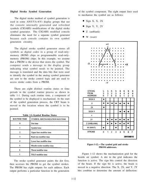
Figure l-12.—The symbol grid and stroke<br />
PROM addresses.<br />
The stroke symbol generator paints the dot first,<br />
then accesses the PROM to get the symbol strokes.<br />
The PROM has eight outputs for each address. Each<br />
output performs a particular function in the generation<br />
Figure 1-12 shows the mechanization grid for the<br />
hostile air symbol. A dot in the grid indicates the<br />
function is active. The sign bits control the direction<br />
of the beam. If the sign bit is active, the beam is<br />
moved in a negative direction. The X, 2X, and Y, 2Y<br />
bits combine to determine the amount of deflection:<br />
1-12


