

nonresident training course - Historic Naval Ships Association
nonresident training course - Historic Naval Ships Association
nonresident training course - Historic Naval Ships Association

You also want an ePaper? Increase the reach of your titles
YUMPU automatically turns print PDFs into web optimized ePapers that Google loves.
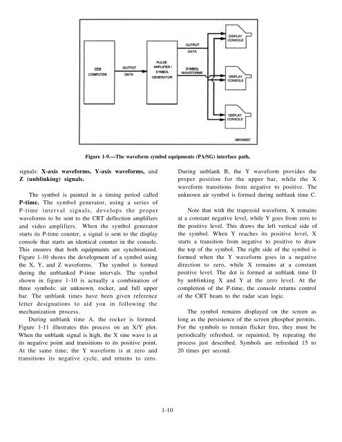
Figure 1-9.—The waveform symbol equipments (PA/SG) interface path,<br />
signals: X-axis waveforms, Y-axis waveforms, and<br />
Z (unblinking) signals.<br />
The symbol is painted in a timing period called<br />
P-time. The symbol generator, using a series of<br />
P-time interval signals, develops the proper<br />
waveforms to be sent to the CRT deflection amplifiers<br />
and video amplifiers. When the symbol generator<br />
starts its P-time counter, a signal is sent to the display<br />
console that starts an identical counter in the console.<br />
This ensures that both equipments are synchronized.<br />
Figure 1-10 shows the development of a symbol using<br />
the X, Y, and Z waveforms. The symbol is formed<br />
during the unblanked P-time intervals. The symbol<br />
shown in figure 1-10 is actually a combination of<br />
three symbols: air unknown, rocker, and full upper<br />
bar. The unblank times have been given reference<br />
letter designations to aid you in following the<br />
mechanization process.<br />
During unblank time A, the rocker is formed.<br />
Figure 1-11 illustrates this process on an X/Y plot.<br />
When the unblank signal is high, the X sine wave is at<br />
its negative point and transitions to its positive point.<br />
At the same time, the Y waveform is at zero and<br />
transitions its negative cycle, and returns to zero.<br />
During unblank B, the Y waveform provides the<br />
proper position for the upper bar, while the X<br />
waveform transitions from negative to positive. The<br />
unknown air symbol is formed during unblank time C.<br />
Note that with the trapezoid waveform, X remains<br />
at a constant negative level, while Y goes from zero to<br />
the positive level. This draws the left vertical side of<br />
the symbol. When Y reaches its positive level, X<br />
starts a transition from negative to positive to draw<br />
the top of the symbol. The right side of the symbol is<br />
formed when the Y waveform goes in a negative<br />
direction to zero, while X remains at a constant<br />
positive level. The dot is formed at unblank time D<br />
by unblinking X and Y at the zero level. At the<br />
completion of the P-time, the console returns control<br />
of the CRT beam to the radar scan logic.<br />
The symbol remains displayed on the screen as<br />
long as the persistence of the screen phosphor permits.<br />
For the symbols to remain flicker free, they must be<br />
periodically refreshed, or repainted, by repeating the<br />
process just described. Symbols are refreshed 15 to<br />
20 times per second.<br />
1-10


