1026 Software and Programming Getting Started - Ivie
1026 Software and Programming Getting Started - Ivie
1026 Software and Programming Getting Started - Ivie

Create successful ePaper yourself
Turn your PDF publications into a flip-book with our unique Google optimized e-Paper software.
<strong>1026</strong> Manual<br />
<strong>Ivie</strong> Technologies, Inc. __________________________________________________________<br />
Installation & Operation Manual<br />
for the<br />
<strong>Ivie</strong> 11002266<br />
DSP Automixer<br />
Updated: November 2007<br />
Copyright 2007<br />
by <strong>Ivie</strong> Technologies Inc.<br />
Printed in U.S.A.
<strong>1026</strong> Manual<br />
<strong>Ivie</strong> Technologies, Inc. __________________________________________________________<br />
Introduction<br />
The <strong>1026</strong> Integrated Automixer/Digital Signal Processor is an EtherNet® controlled, ten input by two<br />
output automixer in combination with a two input by six output DSP signal processor. The automixer<br />
is rich in functions, with automatic level control on each input, remote level control capability <strong>and</strong> sixteen<br />
programmable presets. The DSP inputs <strong>and</strong> outputs are user configurable with combinations of<br />
parametric EQ, delay, comp/limiting, <strong>and</strong> crossover functions being assignable to inputs <strong>and</strong>/or outputs.<br />
Inputs may be assigned to any or all outputs as a pre-EQ input, post-EQ input or as a post-EQ, mixed<br />
input. These assignment options can be very useful when employing a dual channel analyzer to compare<br />
pre <strong>and</strong> post-EQ signals. A total of 50 parametric filters are available to assign in any combination<br />
to DSP inputs <strong>and</strong>/or outputs.<br />
The <strong>1026</strong> Integrated Automixer is an EtherNet® based product <strong>and</strong> cannot be controlled by the same<br />
ANSW+ software that controls <strong>Ivie</strong> matrix mixers, 1/3 octave equalizers etc. The <strong>1026</strong> has its own<br />
control software which is discussed in detail in Section II of this manual titled "<strong>1026</strong> <strong>Software</strong> <strong>and</strong><br />
<strong>Programming</strong>."<br />
System <strong>and</strong> <strong>Software</strong> Requirements<br />
The <strong>1026</strong> Integrated Automixer comes with its own software which is not compatible with other <strong>Ivie</strong><br />
Audio Net® products. The <strong>1026</strong> software is a Windows® application requiring a Windows® based<br />
computer with an EtherNet® port - the faster the computer, the better. The software control screen for<br />
the <strong>1026</strong> will operate in a “off-line” mode without a <strong>1026</strong> actually being attached (this is not true of<br />
other AudioNet+ products such as the 884+). If a <strong>1026</strong> is attached, the software will query the unit <strong>and</strong><br />
display its actual settings. Unlike most other AudioNet+ products that need to be attached for programming<br />
to occur, the <strong>1026</strong> allows completely off-line programming for later upload into a unit. A<br />
hard disk drive is required for overall operation of the system. A mouse is required to use this program.<br />
This Manual<br />
This manual is divided into two sections. Section I: Hardware Overview, describes the mixer <strong>and</strong><br />
DSP signal processor hardware: input/output connections, physical connector assignments, etc. All<br />
information necessary to physically install a unit is contained in this section - everything from bolting<br />
it into a rack to the hardware activation of presets, connection of inputs <strong>and</strong> outputs, remote controls<br />
<strong>and</strong> other physical functions.<br />
Section II: <strong>1026</strong> <strong>Software</strong> <strong>and</strong> <strong>Programming</strong>, describes the programming of the mixers using the<br />
<strong>Ivie</strong>'s Windows® based <strong>1026</strong> software. Computer system requirements are presented in detail, the<br />
software is explained, <strong>and</strong> programming examples are clearly presented.<br />
Both the hardware connections <strong>and</strong> software functions of the <strong>1026</strong> are intuitive <strong>and</strong> user friendly.<br />
Everything necessary for a successful installation is provided within the two sections of this manual.<br />
Page 1
<strong>1026</strong> Manual<br />
<strong>Ivie</strong> Technologies, Inc. __________________________________________________________<br />
Section I: Hardware Overview<br />
Power Supply<br />
The <strong>1026</strong> uses the HUP45-32 universal power supply. It is UL, CSA <strong>and</strong> CE approved, <strong>and</strong> will operate<br />
at line voltages from 100 VAC to 240 VAC, 47 Hz to 63 Hz. It comes with a United States st<strong>and</strong>ard,<br />
three pin power cable. Since the power cable plugs into the power supply, it can be replaced with<br />
a power cable having a connector other than the U.S. st<strong>and</strong>ard connector.<br />
Power Failure<br />
A reasonable question is, "What happens to the programming on the <strong>1026</strong> if power fails?" The answer<br />
is that the memory is nonvolatile, so it "remembers" where it was when power went off, <strong>and</strong> will return<br />
to that same state when power is restored.<br />
<strong>Getting</strong> <strong>Started</strong><br />
Default Settings: The st<strong>and</strong>ard <strong>1026</strong> is preset at the factory so that all ten inputs are assigned to all outputs<br />
via both buses. All inputs are software set for microphone input levels. The Phantom Power is<br />
turned off. The preamp gain is set to 50 dB which means that total gain through the mixer is approximately<br />
50 dB. This is about 70% of the mixer's available gain.<br />
Important Note: Avoid surprises (<strong>and</strong> loud noises)!! Before activating the mixer in an audio chain,<br />
be sure that the software settings for input level, DSP functions, phantom power, etc., are set to your<br />
preferences <strong>and</strong> needs.<br />
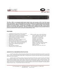
<strong>1026</strong> units are shipped with a 78C-6, six inch, audio bus interconnect cable. This cable must be<br />
plugged into the rear panel of the mixer. It should connect the "Mix Bus Output" to the "DSP Input."<br />
A white line is drawn between these two panel jacks, indicating the st<strong>and</strong>ard 78C-6 connection. There<br />
will be no audio output if this cable is either missing or improperly installed. See Figure 1, below.<br />
Rear Panel View of <strong>1026</strong><br />
OUTPUT INPUT OUTPUT INPUT<br />
78C-6 Bus jumper cable supplied with <strong>1026</strong>.<br />
Note: This cable must be installed as<br />
shown for normal operation.<br />
Figure 1<br />
Page 2
<strong>1026</strong> Manual<br />
<strong>Ivie</strong> Technologies, Inc. __________________________________________________________<br />
Successful Power Up<br />
The HUP45-32 universal power supply is used with the <strong>1026</strong> <strong>and</strong> provides a broad mains voltage operating<br />
range: 100 to 240 VAC, 47 - 63 Hz. Successful powering of the <strong>1026</strong> can be verified by the<br />
lighting of the power indicator LED. When first powered on, the <strong>1026</strong> initiates a self test which<br />
checks a number of their operating parameters to verify proper performance.<br />
Channel Inputs<br />
All <strong>1026</strong> channel inputs are electronically balanced. The preamplifier design provides a very low noise<br />
input with very high common mode rejection. The input is designed to work with a source impedance<br />
of from 50 to 600 Ω <strong>and</strong> provides excellent RF protection. The actual input impedance is 2100 Ω.<br />
All channel inputs can accommodate either microphone or line level inputs. Switching from mic to<br />
line level input is a software function. The input preamp gain trim has a range of from -20 dB to +50<br />
dB. With the input gain trim turned up to + 50 dB, (dynamic mic position), the input terminals are<br />
connected directly to the preamp. Hotter microphones will require preamp gain trim settings of less<br />
than +50 dB. A line level input will require a channel input gain trim setting of approximately 0 to<br />
+10 dB (40 to 50 dB less gain than a mic level input), since line levels are typically hotter than mic<br />
levels by about 35 to 40 dB. The preamp gain stage of the <strong>1026</strong> provides a very high common mode<br />
rejection ratio. The greater the common mode rejection, the greater the degree of immunity to common<br />
mode noise induced in long cable runs between the <strong>1026</strong> <strong>and</strong> the input connector.<br />
Connecting a Dynamic (Moving Coil) Microphone<br />
A st<strong>and</strong>ard dynamic microphone connects to the <strong>1026</strong> via the Euro connectors located on the rear<br />
panel. Pin one of the microphone is connected to the ground terminal on the connector. Pins two (+)<br />
<strong>and</strong> three (-) are connected to their respective terminals. Phantom Power should be OFF. A typical<br />
connection is shown in Figure 2, below:<br />
Dynamic (Moving<br />
Coil) Microphone<br />
Input 1<br />
Figure 2<br />
INPUT SETTINGS<br />
Phantom Pwr: OFF<br />
Preamp gain trim set to -50dB<br />
Page 3
<strong>1026</strong> Manual<br />
<strong>Ivie</strong> Technologies, Inc. __________________________________________________________<br />
Connecting a Condenser Microphone<br />
Condenser microphones connect to the <strong>1026</strong> via the Euro connectors located on the rear panel. Pin one<br />
of the microphone is connected to the ground terminal on the connector. Pins two (+) <strong>and</strong> three (-) are<br />
connected to the plus <strong>and</strong> minus terminals. Phantom Power should be ON. Since condenser mics are<br />
usually "hotter" than dynamic mics, the preamp gain setting should be less than for dynamic mics by<br />
some 10 dB to 20 dB. A typical connection is shown in Figure 3, following:<br />
Figure 3<br />
Connecting a Balanced Line Level to a Channel Input<br />
Line level inputs are connected to the <strong>1026</strong> via the Euro connectors located on the rear of the units. If<br />
the shield is to be connected to the input of the unit, it must be connected to the ground terminal. If the<br />
shield is connected at the piece of equipment sending the signal, it should not be connected at the <strong>1026</strong>.<br />
By connecting the shield at only one end of the cable, potential ground loop problems can be reduced.<br />
The two wires carrying the signal are connected to the plus <strong>and</strong> minus terminals of the channel input.<br />
The input preamp gain trim should be set at about 0 to +10 dB, depending on how "hot" the line level<br />
input is. The Phantom Power should be turned OFF. Figure 4, below, details these connections:<br />
Balanced, Line<br />
Level Output<br />
Signal Flow<br />
Condenser<br />
Microphone<br />
Input 1<br />
Input 1<br />
Figure 4<br />
INPUT SETTINGS<br />
Phantom Pwr: ON<br />
Preamp gain trim set<br />
from +30dB to +40dB<br />
Note: Phantom power is available for<br />
each input <strong>and</strong> can be turned on or off on<br />
each individual channel via the software.<br />
The phantom power supplied is +15 volts<br />
dc for powering condenser microphones.<br />
INPUT SETTINGS<br />
Phantom Pwr: OFF<br />
Preamp gain trim set<br />
from -0dB to +10dB<br />
Note: Good grounding practices dictate<br />
that on balanced lines, the shield should be<br />
connected at only one end of the cable.<br />
Page 4
<strong>1026</strong> Manual<br />
<strong>Ivie</strong> Technologies, Inc. __________________________________________________________<br />
Connecting an Unbalanced Line Level to an Input<br />
A typical unbalanced line has only two conductors. The signal flows in both conductors. The outer<br />
conductor also acts as a shield. Both of these two conductors must be connected to the Euro connector.<br />
The center conductor is connected to the plus terminal. The shielded conductor is connected to the<br />
minus terminal. Depending upon the installation, connection of the shielded conductor to the ground<br />
terminal may be needed in addition to connecting it to the minus terminal. If this additional connection<br />
reduces hum on the input, leave it in place. If the additional connection increases or causes hum<br />
on the input, remove it.<br />
The input gain trim should be set somewhere between 0 <strong>and</strong> +10 dB. Phantom Power Switch should<br />
be set to the OFF position, as shown in Figure 5, following:<br />
Unbalanced, Line<br />
Level Output<br />
Signal Flow<br />
Master Outputs<br />
Input 1<br />
Figure 5<br />
The <strong>1026</strong> has six master outputs. They are referred to as master outputs 1 through 6. Each master<br />
output is electronically balanced. The master outputs are capable of driving a 600 Ω load to a maximum<br />
of +18 dBu.<br />
Connecting a Master Output to a Balanced Line Level Input<br />
INPUT SETTINGS<br />
Phantom Pwr: OFF<br />
Preamp gain trim set<br />
from -0dB to +10dB<br />
The output of the <strong>1026</strong> should be connected to the next piece of equipment in the audio signal chain<br />
via a two-conductor, shielded cable. Care should be taken to make sure the shield is connected at only<br />
one end of the cable. This will help minimize ground loop problems. This connection is demonstrated<br />
in Figure 6 on the following page:<br />
Page 5
<strong>1026</strong> Manual<br />
<strong>Ivie</strong> Technologies, Inc. __________________________________________________________<br />
Input to next piece<br />
of equipment.<br />
BALANCED<br />
INPUT<br />
Figure 6<br />
Connecting a Master Output to an Unbalanced Line Level Input<br />
The output of the <strong>1026</strong> should be connected to the next piece of equipment in the signal chain with a<br />
two-conductor, shielded cable. Care should be taken to make sure that the shield is connected only at<br />
the mixer end of the cable. This will help minimize ground loop problems. Figure 7, following, shows<br />
this connection in detail:<br />
Input to next piece<br />
of equipment.<br />
UNBALANCED<br />
INPUT<br />
Channel Direct Outputs<br />
Signal Flow<br />
Do not connect shield to<br />
ground terminal.<br />
Signal Flow<br />
Output from <strong>1026</strong><br />
Out 1<br />
Do not connect shield to<br />
ground terminal.<br />
Figure 7<br />
Connect to<br />
ground terminal.<br />
Note: Good grounding practices dictate<br />
that on balanced lines, the shield should be<br />
connected at only one end of the cable.<br />
Output from <strong>1026</strong><br />
Connect to<br />
ground terminal.<br />
Each <strong>1026</strong> channel has an unbalanced, Direct Output which accesses analog audio for that individual<br />
channel input only (the Direct Output is + <strong>and</strong> the ground of the associated input is -). If an input<br />
Out 2<br />
Out 1<br />
Out 2<br />
Page 6
<strong>1026</strong> Manual<br />
<strong>Ivie</strong> Technologies, Inc. __________________________________________________________<br />
channel is not assigned to one of the two signal buses, the only output from that channel would be<br />
found at the Direct Output for that input channel. The Direct Outputs provide a very useful feature.<br />
Any input channel, for example, could be used as a microphone-to-line preamplifier. The (unbalanced)<br />
line level output would appear at the channel's Direct Output. The outputs can be taken as separate<br />
outputs for any number of purposes. The Direct Output is connected through a 604 Ω resistor to the<br />
Euro terminal block on the rear panel. Direct Outputs can be connected in parallel with other Direct<br />
Outputs when a mix of Direct Outputs is required. There will, of course, be a 6 dB drop in gain whenever<br />
the number of outputs being connected together is doubled.<br />
Level Controls<br />
There are sixteen level controls on the <strong>1026</strong>, ten for the channel inputs <strong>and</strong> six for the master outputs.<br />
All level controls function alike. There are three level functions associated with each control: Level,<br />
Range, <strong>and</strong> Trim (Gain Trim).<br />
Level<br />
“Level” is the actual, operating, channel level <strong>and</strong> should be thought of as a common volume control<br />
that would be located on the front panel of any st<strong>and</strong>ard mixer. The channel Level can be adjusted<br />
using a remote control, or via the "slider pots" of the <strong>1026</strong> software.<br />
The Level control works as an in-line attenuator <strong>and</strong> can attenuate signal from 0 dB to -99 dB. It is<br />
very helpful to think of "turning down" the volume as opposed to "turning up" the gain. The gain for<br />
the channel is set at input preamplifier stage. The Level control acts as an attenuator to the audio signal<br />
through that channel.<br />
Range Control<br />
As previously noted, the Level control has an adjustment range of 100 dB. The Range control<br />
(accessed via a pop-up window in the <strong>1026</strong> software) allows the limiting, or restricting of the actual<br />
operating range of the Level control. The ability to limit the volume control range is very helpful in<br />
certain applications. Any type of meeting room with a volume control located in the room can benefit<br />
from range limitation. If, for example, the volume control range were limited to 20 dB, the sound system<br />
could never be turned all the way off. There would always be some sound from the system when<br />
somebody talked into or tapped on a microphone. If there were always some sound, operators would<br />
not mistakenly believe a system turned down below the audible level had died, or was not functioning.<br />
They would, instead, begin to look for a volume control to turn the system up.<br />
The Range control limits the range of the volume control. Instead of the full 100 dB range, a much<br />
smaller range can be selected. The range is referenced from full on, or zero dB of attenuation, to a set<br />
number of dB below full on. The range is set by entering the Range menu <strong>and</strong> setting the control range<br />
in dB.<br />
The Range control has a special feature. It is called "Range Plus Off." A limited control range can be<br />
set with the final step in that range being full off, or full attenuation. This gives the volume control a<br />
limited range, but still allows for a full "Off" selection.<br />
Page 7
<strong>1026</strong> Manual<br />
<strong>Ivie</strong> Technologies, Inc. __________________________________________________________<br />
Trim (Preamp Gain Trim)<br />
Trim is a very powerful, software based feature of the <strong>1026</strong>. It allows the setting of the maximum<br />
level, or gain, in a particular channel. The maximum gain through the channel can be limited, so as to<br />
prevent feedback from occurring when a channel Level control is turned all the way up. The Trim is<br />
also used to allow for microphone versus line level input signals, as previously discussed. Keep in<br />
mind that the majority of gain in the channel is set in the input preamplifier stage. The Trim adjustment<br />
has a range of from -20 dB to +60 dB, which allows not only for microphone or line level input<br />
configurations, but also can be used to permanently limit the maximum gain available to a channel.<br />
Figure 8, following, shows the relationship in the Level, Range <strong>and</strong> Gain Trim adjustments:<br />
Properly adjusted<br />
Trim can help limit<br />
feedback potential.<br />
Trim (Gain Trim) Level Range Range <strong>and</strong> Trim<br />
+60<br />
+59<br />
+58<br />
+57<br />
+56<br />
+55<br />
+54<br />
+53<br />
+52<br />
+51<br />
+50<br />
+49<br />
+48<br />
+47<br />
0<br />
-1<br />
-2<br />
-3<br />
-4<br />
-5<br />
-6<br />
-7<br />
-8<br />
-17<br />
-18<br />
-19<br />
-20<br />
Available Volume<br />
Control Range<br />
Loudest<br />
0<br />
-1<br />
-2<br />
-3<br />
-4<br />
-5<br />
-6<br />
-7<br />
-8<br />
-9<br />
-10<br />
-39<br />
-40<br />
-41<br />
-42<br />
-43<br />
-47<br />
-52<br />
-61<br />
-70<br />
-80<br />
-99<br />
Softest<br />
Restricted<br />
Volume<br />
Control Range<br />
Loudest<br />
Softest<br />
Figure 8<br />
Restricted Volume<br />
Control Range <strong>and</strong><br />
Restricted Max Gain<br />
Loudest<br />
Softest<br />
Note: The taper of the Level <strong>and</strong><br />
Range controls is shown in this<br />
illustration. Both decrement in<br />
1dB steps to -40dB. Then the<br />
taper changes as shown.<br />
In this example, the range<br />
of the Level Control is<br />
restricted to 20dB <strong>and</strong> the<br />
Trim control has been used<br />
to trim maximum gain to<br />
10dB below “full on.”<br />
Note: The normal full range of the VCA is 100 dB (0 to -99). If less than the full range is desired<br />
(perhaps only 20dB of range may be wanted), the Range control can be used to limit that range. If<br />
less than the full available gain is desired, the Gain Trim control can be used to limit the maximum<br />
gain available. If the maximum gain available is limited by the Gain Trim control, the full 0 to -99 dB<br />
0<br />
-1<br />
-2<br />
-3<br />
-4<br />
-5<br />
-6<br />
-7<br />
-8<br />
-9<br />
-10<br />
-17<br />
-18<br />
-19<br />
+50<br />
+49<br />
+48<br />
+47<br />
-20 -27<br />
-28<br />
-29<br />
-30<br />
Page 8
<strong>1026</strong> Manual<br />
<strong>Ivie</strong> Technologies, Inc. __________________________________________________________<br />
of attenuation is still available below the maximum level that has been set by the Gain Trim control,<br />
unless, of course, that range of attenuation has been limited by using the Range control.<br />
Remote Volume Controls<br />
Please note: Before any remote control can become active, the <strong>1026</strong> must be programmed to accept<br />
input from a remote control.<br />
The ten input channel volume controls of the <strong>1026</strong> <strong>and</strong> the six master output volume controls may all<br />
be controlled remotely. Two different types of remote controls can be used: a rotary style using a<br />
potentiometer, <strong>and</strong> an up/down push button style. (The RM-1 <strong>and</strong> RM-2 up/down push button controls<br />
look like pots, not up/down buttons, to the <strong>1026</strong>.) All power required by the remotes is supplied by the<br />
<strong>1026</strong>. The RMT (remote) voltage supplied by the <strong>1026</strong> is current limited <strong>and</strong> must be used only for the<br />
remotes. The RMT voltage cannot be used to power any other type of external device, except LED's.<br />
The control range of all remotes follows the programming of the <strong>1026</strong> for channel <strong>and</strong> master volume<br />
controls. The programming can be used to limit the range of the remote control (Range Function) <strong>and</strong><br />
the maximum level (Trim Function) of the remote volume controls. A limited range plus "OFF" can<br />
also be programmed.<br />
Using a Potentiometer Remote<br />
Please note: Before any remote control can become active, the <strong>1026</strong> must be programmed to accept<br />
input from the remote - the software RP Button for that channel must be pressed.<br />
The <strong>Ivie</strong> RP-1 (Remote Pot-1) remote volume control is designed for use with the <strong>1026</strong> <strong>and</strong> other <strong>Ivie</strong><br />
matrix mixers. It is a potentiometer mounted on single-gang, black anodized, wall plate. The <strong>Ivie</strong><br />
RP-1S has a DPDT switch mounted on the plate in addition to the potentiometer. The switch is<br />
typically used for background music on/off.<br />
A st<strong>and</strong>ard 10k Ω, linear taper, potentiometer is connected as illustrated in Figure 9, following.<br />
Rmt+ Rmt Level Preset Inputs Function Out<br />
5 6 7 8 1 2 3 4 5 6 7 8 1 2 3 4 5 6 7 8<br />
10k Linear<br />
Taper Pot<br />
Figure 9<br />
Potentiometer<br />
Front View<br />
Note: In Figure 9, notice that the potentiometer is connected across the RMT voltage <strong>and</strong> ground. The<br />
Rmt +<br />
LOUD<br />
SOFT<br />
Rmt +<br />
Soft Loud<br />
Channel 5<br />
Rmt Level<br />
Page 9
<strong>1026</strong> Manual<br />
<strong>Ivie</strong> Technologies, Inc. __________________________________________________________<br />
wiper of the pot is connected to the Remote Level channel terminal. As the wiper gets closer to<br />
ground, the volume level increases. As the wiper gets closer to RMT+, the volume level decreases.<br />
The RMT voltage cannot be used to power any other type of external device, except LEDs.<br />
When a limited volume range has been programmed for a channel, the number of steps in that range is<br />
divided into the number of degrees of rotation in the potentiometer. Thus, a limited range will be<br />
exp<strong>and</strong>ed around the full rotation of the potentiometer.<br />
Potentiometer style remotes cannot be paralleled together to provide remote control for one channel<br />
from several different locations. <strong>Software</strong> volume control is disabled when a potentiometer style<br />
remote is connected <strong>and</strong> activated by the programming.<br />
Once a <strong>1026</strong> has been programmed for a remote potentiometer, the unit will "look" for a pot connected<br />
to the remote level terminal. If it does not detect the pot, it will adjust the level as dictated by the software<br />
settings. When a pot is connected, the unit detects the connection <strong>and</strong> sets the level as dictated by<br />
the pot. The unit will automatically switch between the software setting <strong>and</strong> the remote pot setting. If<br />
the pot is disconnected, the <strong>1026</strong> will automatically switch back to the software setting.<br />
In some applications, this automatic switching is very advantageous. Day-to-day operations could proceed<br />
with the software volume settings. For special events, a plug-in remote control could be used<br />
which would override the normal settings. At the conclusion of the event, unplugging the remote<br />
would restore the software volume settings.<br />
<strong>Ivie</strong> manufactures portable remote control panels that are compatible with the <strong>1026</strong>. The RMA-10L<br />
Remote Control can control 10 channels, <strong>and</strong> comes with 10 feet of cable <strong>and</strong> a connector. It is supplied<br />
with a matching wall plate <strong>and</strong> connector assembly. If only 6 channels are needed, an <strong>Ivie</strong><br />
RMA-6L may be used, which also comes with a matching wall plate <strong>and</strong> connector assembly.<br />
Using Up/Down Push Button Remotes<br />
Please note: Before any remote control can become active, the <strong>1026</strong> must be programmed to accept<br />
input from that remote control.<br />
<strong>Ivie</strong> manufactures two types of push button remote level controls that can be used with the <strong>1026</strong>. The<br />
first set of push button remotes consists of the RM-1 <strong>and</strong> RM-2 microprocessor based remote controls.<br />
The RM-1 controls a single channel, while the RM-2 has two sets of push buttons to control two channels.<br />
The push button remotes “look like” pots to the <strong>1026</strong> <strong>and</strong> are therefore connected the same way<br />
that potentiometer remotes would be connected. In order for an RM-1 or RM-2 to function, the <strong>1026</strong><br />
must have its software “Remote Pot” control enabled. The RM-1 <strong>and</strong> RM-2 have on-board microprocessors,<br />
so they must be fed power from the <strong>1026</strong> as well as be connected to the remote control<br />
ports. They have up/down buttons <strong>and</strong> an LED bar graph to provide visual indication of level. They<br />
are themselves programmable for maximum level, minimum level, <strong>and</strong> “wake up,” or turn on level.<br />
Once programmed for maximum <strong>and</strong> minimum levels, the LED bar graph will automatically be spread<br />
over that range, that is, minimum level will light one LED on the bar graph <strong>and</strong> maximum level will<br />
Page 10
<strong>1026</strong> Manual<br />
<strong>Ivie</strong> Technologies, Inc. __________________________________________________________<br />
light all the LEDs on the bar graph. These controls can be factory programmed to track one another<br />
automatically in room combining applications.<br />
The second type push button remote is the <strong>Ivie</strong> RB-1. It is a simple, less expensive, up/down push button.<br />
It consists of a single-gang, black anodized, wall plate containing "Up" <strong>and</strong> "Down" push buttons,<br />
three resistors <strong>and</strong> a terminal block for wiring connections. Each push of a button increments or decrements<br />
the volume level by one step. Several can be paralleled together for remote level control capability<br />
from more than one location. In order for the RB-1 to function, the <strong>1026</strong> must have its software<br />
“Remote Button” control enabled. The <strong>1026</strong> provides the necessary logic for RB-1’s to track each<br />
other in room combining applications.<br />
Making Custom Up/Down Buttons<br />
As illustrated in Figure 10, below, two push buttons <strong>and</strong> three 3.3k Ω, 1/4 watt resistors, are needed for<br />
a push button remote. The resistors are connected across RMT voltage <strong>and</strong> ground, forming a voltage<br />
divider. All power required by the remotes is supplied by the <strong>1026</strong>. The RMT voltage supplied by the<br />
<strong>1026</strong> is current limited <strong>and</strong> must be used only for the remotes. The RMT voltage cannot be used to<br />
power any other type of external device, except LEDs.<br />
Hardware Activation of Presets<br />
Connection of Push Button Remote Volume Controls<br />
Rmt+ Rmt Level Preset Inputs Function Out<br />
1 2 3 4 5 6 7 8<br />
5 6 7 8 1 2 3 4 5 6 7 8<br />
LOUD LOUD<br />
SOFT<br />
Channel 5<br />
Location “A”<br />
Figure 10<br />
Channel 5<br />
Location “B”<br />
Presets can be activated remotely on the <strong>1026</strong> via a switch connected to the appropriate terminals on<br />
the rear panel. Presets can also be activated via the <strong>1026</strong> software. There are sixteen presets associated<br />
with the mixer section of the <strong>1026</strong> which are not mutually exclusive. In other words, more than one of<br />
SOFT<br />
UP/DOWN Pushbutton<br />
(Shown in parallel with a second remote control)<br />
3.3k Ω<br />
3.3k Ω<br />
3.3k Ω<br />
Page 11
<strong>1026</strong> Manual<br />
<strong>Ivie</strong> Technologies, Inc. __________________________________________________________<br />
these presets can be active at a time. There are also sixteen presets associated with the digital signal<br />
processing section of the <strong>1026</strong> which are mutually exclusive, that is, only one of these presets can be<br />
active at once.<br />
While there are sixteen presets for the mixer section <strong>and</strong> sixteen presets for the DSP section of the<br />
<strong>1026</strong> (all of which can all be activated or deactivated via the <strong>1026</strong> software), there are only eight hardware<br />
connections on the rear panel of the <strong>1026</strong> for activating presets. This means that there are only<br />
eight preset combinations which can be activated by an external contact closure.<br />
One contact closure between a Preset Input <strong>and</strong> ground (using a switch or relay) actually performs<br />
three simultaneous functions. A contact closure between Preset Input 1 <strong>and</strong> ground will<br />
activate Preset 1 in the mixer section, Preset 1 in the DSP section, <strong>and</strong> additionally, will activate<br />
Function Out 1. Figure 11, following, details the connections for activating presets.<br />
Note: Connecting a Preset Input to<br />
ground activates that preset <strong>and</strong> activates<br />
a corresponding Function Output.<br />
Latching the switch shown above,<br />
between Preset Input #1 <strong>and</strong> ground, for<br />
example, activates Preset #1 <strong>and</strong><br />
Function Output #1. Activating Preset #2<br />
activates Function Output #2, etc.<br />
Figure 11<br />
Activating Presets on Two Units at the Same Time<br />
Presets on two different <strong>1026</strong>’s may be activated at the same time. Diodes must be used to isolate one<br />
<strong>1026</strong> from the other. A st<strong>and</strong>ard 1N914 diode can be used, as shown in Figure 12, following:<br />
Diodes should be used for isolation when<br />
connecting the presets of two different<br />
<strong>1026</strong>’s in parallel.<br />
Close switch to activate Preset<br />
#1 on both <strong>1026</strong> mixers<br />
Rmt Lvl Preset Inputs<br />
5 6 7 8 1 2 3 4 5 6 7 8<br />
IN914<br />
IN914<br />
Figure 12<br />
Preset Inputs<br />
1 2 3 4 5 6 7 8<br />
Preset Inputs<br />
1 2 3 4 5 6 7 8<br />
<strong>1026</strong> #1<br />
<strong>1026</strong> #2<br />
Function Out<br />
1 2 3 4 5 6 7 8<br />
Page 12
<strong>1026</strong> Manual<br />
<strong>Ivie</strong> Technologies, Inc. __________________________________________________________<br />
Function Output<br />
Each Function Output on the <strong>1026</strong> can be used for controlling external devices, typically LED's. A<br />
Function Output is not an audio output. It is a low voltage, DC, solid-state switch. This switch is activated<br />
as part of a preset group as explained previously under the heading Hardware Activation of<br />
Presets found on pages 11 <strong>and</strong> 12. It can be used to light an LED, or with an external (installer provided)<br />
power supply, could be used to control an external relay.<br />
On the <strong>1026</strong>, Function Output number 1 is activated when Preset 1 is activated, Function Output 2 is<br />
activated when Preset 2 is activated, <strong>and</strong> so on.<br />
The Function Output is the open collector type. The collector is normally open until the Function<br />
Output is activated at which time the collector is brought to ground potential. Please underst<strong>and</strong> that<br />
NO voltage is supplied by this switch. It is ONLY a switch to ground. Since this is a transistor, polarity,<br />
maximum voltage <strong>and</strong> current limits must be observed when connecting external devices.<br />
Maximum current through the switch should not exceed 200 mA. Voltage across the switch should not<br />
exceed 30 VDC. Figure 13, below, shows an LED connected to the Function Output. The Remote+<br />
terminal on the rear of the <strong>1026</strong> has a built-in power supply voltage for use with LEDs <strong>and</strong> remote<br />
controls. It must not be used for any other purpose than LEDs <strong>and</strong> remote controls. Figure 13, following,<br />
shows the proper connection of an LED used to provide visual indication of Function Out<br />
status:<br />
Two LED’s are connected between the<br />
Function Output <strong>and</strong> Remote+ terminals.<br />
They are illuminated when Preset #1 is activated,<br />
providing positive status indication.<br />
Note: The LED’s can be placed<br />
at different locations.<br />
Ground Link Connections<br />
Rmt+ Rmt Level Preset Inputs Function Out<br />
5 6 7 8 1 2 3 4 5 6 7 8 1 2 3 4 5 6 7 8<br />
220 Ω, 1/4 Watt<br />
Resistors<br />
Figure 13<br />
The four position terminal block located on the rear of the <strong>1026</strong> has two terminals to assist in properly<br />
grounding the units. The two terminals are labeled "Audio Gnd" <strong>and</strong> "Chassis Gnd."<br />
LED’s<br />
Page 13
<strong>1026</strong> Manual<br />
<strong>Ivie</strong> Technologies, Inc. __________________________________________________________<br />
There is a jumper connected between the "Audio Gnd" <strong>and</strong> "Chassis Gnd" terminals. This jumper<br />
should remain in place unless more than one unit is being connected together. If more than one unit is<br />
being used, they should be wired together in a "star ground" configuration. Figure 14 below shows this<br />
method of grounding. “Star grounding” greatly reduces noise problems due to ground loops between<br />
units.<br />
Ground link<br />
CONNECTED<br />
between Audio<br />
<strong>and</strong> Chassis<br />
ground.<br />
Ground link<br />
REMOVED<br />
between Audio<br />
<strong>and</strong> Chassis<br />
ground.<br />
Ground<br />
Link<br />
See Manual<br />
Ground<br />
Link<br />
See Manual<br />
Ground<br />
Link<br />
See Manual<br />
Mixer #1<br />
Mixer #2<br />
Mixer #3<br />
Master<br />
Mute<br />
Master<br />
Mute<br />
Master<br />
Mute<br />
Figure 14<br />
Recommended<br />
Grounding Procedure for<br />
Multiple Mixers<br />
This grounding procedure will help<br />
minimize noise due to ground loops<br />
between mixers.<br />
1. Make certain that the first mixer<br />
in the system has a jumper between<br />
the Audio <strong>and</strong> Chassis ground terminals<br />
on the rear of the mixer.<br />
2. Remove the Audio to Chassis<br />
ground jumper on all other mixers.<br />
3. Use 16 AWG wire or greater <strong>and</strong><br />
connect the Audio Ground of each<br />
successive mixer to the Audio<br />
Ground of the first mixer. There<br />
should be a “home run” wire from<br />
each mixer to the first mixer. Do not<br />
“daisy chain” them together.<br />
Please note that the unit in this “star ground” scheme has its jumper installed between the audio <strong>and</strong><br />
chassis ground terminals. All other units have their jumpers removed. A large gauge wire, 16AWG or<br />
greater, is connected between each successive unit’s Audio Gnd terminal <strong>and</strong> the Ground terminals on<br />
the first unit. This separate wire runs all the way from each unit back to the first <strong>1026</strong>, which is very<br />
important. Do not daisy chain from one Audio Gnd terminal to another <strong>and</strong> then to the first <strong>1026</strong>.<br />
When connecting to the first unit, the Chassis Gnd terminal can be used if the Audio Gnd terminal gets<br />
too congested.<br />
Page 14
<strong>1026</strong> Manual<br />
<strong>Ivie</strong> Technologies, Inc. __________________________________________________________<br />
Section II: <strong>1026</strong> <strong>Software</strong> <strong>and</strong> <strong>Programming</strong><br />
<strong>Getting</strong> <strong>Started</strong><br />
<strong>Software</strong> Installation<br />
<strong>1026</strong> software is shipped with the <strong>1026</strong>. An install utility is provided with the software to help install it<br />
properly. Additionally, the latest version of the software is always available for downloading from <strong>Ivie</strong>’s<br />
web site at www.ivie.com. The st<strong>and</strong>ard <strong>1026</strong> software is for Windows® (98 or above) operating systems.<br />
To install the software, insert the <strong>1026</strong> software CD into the computer’s CD drive, navigate to the<br />
CD <strong>and</strong> click on the “setup.exe” file.<br />
Alternatively, download the software from the <strong>Ivie</strong> website to your desktop, then navigate to the downloaded<br />
file <strong>and</strong> double click on it. <strong>Ivie</strong> recommends that you download the software from our website as<br />
you will be assured of having the latest version.<br />
St<strong>and</strong>ard installation of the <strong>1026</strong> software will install an icon on your desktop screen, which can be<br />
used to start the software. The <strong>1026</strong> software can be run off-line, with no <strong>1026</strong> connected. This can<br />
be very useful to the installer or consultant who wishes to do some setup prior to arriving at the job<br />
site. Configurations can be changed, presets programmed, levels set, <strong>and</strong> so on, with the off-line software.<br />
This programming may then be saved to a file <strong>and</strong> uploaded to the hardware at a later time.<br />
EtherNet® Connections Between a Computer <strong>and</strong> a <strong>1026</strong><br />
Wireless EtherNet® Connection to a <strong>1026</strong><br />
An interesting possibility available with the EtherNet® controlled <strong>1026</strong> is to connect it to the computer<br />
using a wireless link. This can be done using a relatively inexpensive wireless EtherNet® hub <strong>and</strong> can<br />
allow the installer or consultant to make level <strong>and</strong> signal processing adjustments from a laptop or other<br />
computer from any location within range of the wireless link. Connection is intuitive <strong>and</strong> not difficult.<br />
St<strong>and</strong>ard EtherNet cables would be used (not crossover cables) <strong>and</strong> st<strong>and</strong>ard wiring for EtherNet® hub<br />
usage applies.<br />
St<strong>and</strong>ard EtherNet® Connection to a <strong>1026</strong> (Crossover Cable Required)<br />
On the rear panel of the <strong>1026</strong> is a st<strong>and</strong>ard RJ45 connector. Since the <strong>1026</strong> is a st<strong>and</strong>ard EtherNet®<br />
device, connection from a computer to the RJ45 EtherNet® port on the back of the <strong>1026</strong> is done in the<br />
same way one would connect any EtherNet® device to a computer. A direct, CAT 5 cable connection<br />
from the EtherNet® port of a computer to the RJ45 EtherNet® connector on the back of the <strong>1026</strong> is<br />
possible. A “crossover” cable is required for this type of connection. If connection is made using a hub<br />
or switch between the computer <strong>and</strong> the <strong>1026</strong> (such as in the wireless connection described above),a<br />
crossover cable is not required. Figure 15, on the following page, shows the proper wiring for a<br />
crossover cable:<br />
Page 15
<strong>1026</strong> Manual<br />
<strong>Ivie</strong> Technologies, Inc. __________________________________________________________<br />
Additional <strong>Software</strong>: 485MON32<br />
Figure 15<br />
The CD included with the <strong>1026</strong> contains another highly useful program in addition to the <strong>Ivie</strong> <strong>1026</strong><br />
software (which can also be downloaded from the <strong>Ivie</strong> website). It is called 485MON32. This is a monitoring<br />
program that is used while plugged into the EtherNet® connection of the <strong>1026</strong>. 485MON32 can be<br />
a tremendous help in programming external control devices such as touch screens.<br />
An “EtherNet <strong>Programming</strong> Manual” is available from <strong>Ivie</strong>; either by request to the factory, or by downloading<br />
from <strong>Ivie</strong>'s web site at www.ivie.com. This manual is intended for those programming external<br />
controls (such as AMX® or Crestron® touch panels) <strong>and</strong> provides both the HEX <strong>and</strong> ASCII code for<br />
controlling all functions of the EtherNet® products. Use of the 485MON32 program when programming<br />
is very beneficial <strong>and</strong> highly recommended.<br />
Starting the <strong>1026</strong> <strong>Software</strong> with a Unit Connected to the Network<br />
Successful connection of a <strong>1026</strong> to the network is indicated by the green LED on the front panel of the<br />
Page 16
<strong>1026</strong> Manual<br />
<strong>Ivie</strong> Technologies, Inc. __________________________________________________________<br />
<strong>1026</strong>. When a computer is also successfully connected to the network as well, starting the <strong>1026</strong> software<br />
will bring up the first software screen, the Network Information Screen. The window on the right will<br />
show any <strong>1026</strong> units that are found on the network. The window on the left will show any <strong>1026</strong> units on<br />
the network that are "IP compatible" with your computer's network setup. If a mixer is identified in the<br />
right-h<strong>and</strong> window, but not in the left-h<strong>and</strong> window, it is not currently network-address compatible, <strong>and</strong><br />
therefore, cannot be controlled with your computer's network settings. Because the <strong>1026</strong> is an IP addressable<br />
device, it comes with a default IP address <strong>and</strong> subnet mask programmed into it. The default IP<br />
address in the <strong>1026</strong> may not (probably will not) be compatible with the IP setup in your computer.<br />
To make a compatible connection between your computer's network port <strong>and</strong> the <strong>1026</strong>, something will<br />
have to change. You COULD change the networking setup of your computer to that of the <strong>1026</strong>, but<br />
that is inconvenient, at best. The <strong>Ivie</strong> <strong>1026</strong> software provides a means of changing the IP setup of the<br />
<strong>1026</strong> to match that of your computer. With a single software button push, you can change the <strong>1026</strong><br />
networking setup to be compatible with your computer.<br />
Simply click on the “Match Subnet” button in the Network Info screen. The previously incompatible<br />
<strong>1026</strong> will be adjusted to operate on your computer's networking settings, <strong>and</strong> is now identified in the lefth<strong>and</strong><br />
"Units Controllable From This Computer" window. If, in the future, a different computer needs to<br />
be used to adjust the <strong>1026</strong>, this IP adjustment procedure can be done again as the software is started up to<br />
change the <strong>1026</strong> to the new computer's network settings.<br />
<strong>Programming</strong> the <strong>1026</strong><br />
Presets<br />
A <strong>1026</strong> has sixteen, nonexclusive presets available on the mixer side, <strong>and</strong> sixteen exclusive presets on the<br />
DSP section. On the DSP side, configuration <strong>and</strong> setup information can be saved to one preset only, or to<br />
all sixteen presets. Thus, universal programming can be saved to all presets, while specific information<br />
can be saved to one preset only. Additionally, the binary logic preset port configuration feature allows a<br />
combination of mixer <strong>and</strong> DSP presets to be activated simultaneously by a software comm<strong>and</strong>, or a contact<br />
closure. There are eight contacts on the rear panel to provide the binary logic closures which results<br />
in 256 possible preset activation combinations.<br />
<strong>Programming</strong> Preparation<br />
Wiring a <strong>1026</strong> into a system, as described in detail in Section I of this manual, is simple <strong>and</strong> straight forward.<br />
St<strong>and</strong>ard audio wiring <strong>and</strong> grounding techniques should be employed. Inputs <strong>and</strong> outputs are<br />
clearly labeled on the rear chassis <strong>and</strong> the detachable Euroblock connectors are labeled as well. Front<br />
panel LEDs clearly indicate signal passing through the unit. Once the <strong>1026</strong> has been wired into the system<br />
<strong>and</strong> the <strong>1026</strong> software has been loaded, programming can begin.<br />
When the <strong>1026</strong> software is activated, it first polls the network to locate any units on the network. After<br />
polling is complete, the default screen for the <strong>1026</strong> software comes up. This control screen, as shown in<br />
Figure 16 on the following page, depicts the architecture of the <strong>1026</strong> in graphic form. The ten inputs are<br />
shown on the left, the Routing Matrix at the top <strong>and</strong> the six outputs on the right. The various signal processing<br />
modules that can be activated or deactivated for the inputs <strong>and</strong> outputs are depicted by the blocks<br />
labeled "DSP" on the two input buses <strong>and</strong> the six outputs.<br />
Page 17
<strong>1026</strong> Manual<br />
<strong>Ivie</strong> Technologies, Inc. __________________________________________________________<br />
Figure 16<br />
Important Note: Left clicking on the "DSP" block brings up the PEQ Filter Control Pop Up Window.<br />
Right clicking on the "DSP" block activates a menu allowing selection of pop up control windows for<br />
Delay, or Compressor as well as for Equalization<br />
<strong>1026</strong> Main Control Screen<br />
The first step in programming the <strong>1026</strong> is to configure the unit for the signal processing requirements<br />
of the application. To configure the unit, the DSP Configure pop-up window (located under the “Edit”<br />
pull-down menu of the main control screen) is used as described below. Configuring a <strong>1026</strong> using the<br />
DSP Configure pop-up window is one of the first steps in programming the unit.<br />
DSP Configure (Edit Pull-down Menu)<br />
Accessed from the “Edit” pull down menu, the DSP Configure pop-up window allows the creation of one<br />
Page 18
<strong>1026</strong> Manual<br />
<strong>Ivie</strong> Technologies, Inc. __________________________________________________________<br />
or more configurations to more nearly match the specific needs of an application. While the architecture<br />
of two in by six out is fixed, the signal control modules (PEQ, delay compression/limiting, crossovers<br />
etc.) can be activated or deactivated for each input <strong>and</strong> output, allowing many possible configurations.<br />
The DSP Configure pop-up window is shown in Figure 17 below:<br />
Figure 17<br />
The number of PEQ filters, amount of delay, etc. can also be distributed to inputs <strong>and</strong>/or outputs as<br />
desired. A configuration can be saved to one preset or to all presets. Thus, a desired common configuration<br />
can be created <strong>and</strong> saved to all presets with just one click of the mouse, or a complete reconfiguration<br />
of the <strong>1026</strong> with each preset is possible.<br />
Mix Bus Input Path<br />
One of the individual functions in the configuration screen, crossovers, can be turned “on” or “off,”<br />
depending on whether that function is needed for the intended application. A gray color indicates a disabled<br />
crossover <strong>and</strong> yellow indicates an enabled crossover. Placing the cursor on a crossover <strong>and</strong> clicking<br />
Page 19
<strong>1026</strong> Manual<br />
<strong>Ivie</strong> Technologies, Inc. __________________________________________________________<br />
will alternately enable <strong>and</strong> disable the crossover. Once a configuration has been selected, that configuration<br />
can be saved to one or to all presets.<br />
The next modules shown in the signal processing chain are the PEQ modules. Clicking on the number<br />
tab allows the selection of the appropriate number of PEQ filters in the input path for the required application.<br />
Each of the filters can be individually defined as parametric, High-cut Low-cut, Hi-shelf, etc. as<br />
required. It may be necessary to configure a filter such as a Low-cut filter with a sharper or more complex<br />
characteristic. This type of filter is called an “extended” filter, due to its extended capabilities, <strong>and</strong> it<br />
consumes two of the fifty available “filter units,” instead of one.<br />
To enable extended filters, click on the “+” box directly beneath the number tab in the filter module<br />
block. The small “(2)” indicates that using a more complex filter will allocate two filter units instead of<br />
one. Clicking this box makes available sharper <strong>and</strong> more complex filter types, such as Butterworth,<br />
Bessel, <strong>and</strong> Linkwitz-Riley, on either end of the spectrum.<br />
Resource Allocation Table<br />
Before making changes to the PEQ modules, it is necessary to consider the Resource Allocation Table,<br />
found centered on the left side of the DSP Configuration screen (see Figure 17, on the preceding page).<br />
The first line of the table indicates allocation of the PEQ filters in the <strong>1026</strong>. The total number of filter<br />
units available is fifty. Both PEQ’s <strong>and</strong> Crossovers draw filter units from this bank of fifty filter units.<br />
These filter units can be allocated throughout the inputs <strong>and</strong> outputs on the DSP Configuration screen as<br />
they are needed. The total of fifty filter units cannot be exceeded.<br />
After the PEQ function module, the next module in the input path is a Compressor/Limiter. A Delay<br />
Module follows the Compressor/Limiter. It is possible to select the maximum amount of delay<br />
allocated to each of the Delay Modules. The second line in the Resource Allocation Table is very helpful<br />
in this process. Up to 1,365 milliseconds of delay is available for allocation.<br />
Going from left to right on the DSP Configure screen (Figure 17), following the input Delay Modules, is<br />
the Routing Matrix. The Routing Matrix is discussed in detail in the section of the manual titled “Signal<br />
Routing” (see page 21). Located between the Routing Matrix <strong>and</strong> the Output Paths, are the Crossover<br />
Modules. Clicking on one of the Crossover Modules brings up one of three states: Inactive, 2-Way or 3-<br />
Way. Select the appropriate state for the application by successive clicking. Note: The slopes of the<br />
crossovers generally require use of steeper filters, thus a greater number of filter units will be employed in<br />
the Resource Allocation Table when crossovers are selected.<br />
Output Paths<br />
Each of the six outputs of the <strong>1026</strong> has an output path with Delay, PEQ, <strong>and</strong> Compressor/Limiter<br />
Modules. Once the <strong>1026</strong> has been configured, it is time to return to the main <strong>1026</strong> control screen to<br />
assign the signal routing <strong>and</strong> complete the setup of the unit. This is accomplished by pressing the<br />
“Accept” button.<br />
Page 20
<strong>1026</strong> Manual<br />
<strong>Ivie</strong> Technologies, Inc. __________________________________________________________<br />
Signal Routing<br />
The <strong>1026</strong> control screen shows the two inputs of the unit feeding several audio buses. There is a pre-EQ<br />
<strong>and</strong> post-EQ feed from each input, as well as a mixed feed from both inputs. Each of these feeds can be<br />
routed to any output. To complete the routing of an input to an output, place the cursor on the Routing<br />
Matrix graphically illustrated (with vertical lines) between the inputs <strong>and</strong> outputs. Select an output for<br />
connection by placing the cursor on the Routing Matrix directly in line with the red line which graphically<br />
illustrates the feed to the output. Click the mouse. A connection will be made <strong>and</strong> will appear on the<br />
screen. Successive clicks of the mouse will toggle through each of the possible input feeds to the selected<br />
output. The signal path illustrated will change color each time a change is made to help clarify the selection.<br />
An input to output connection that has been made is illustrated in Figure 18 below:<br />
Figure 18<br />
As shown, the post-EQ feed from input B has been routed to output number 1. Notice the position of<br />
the cursor on the Routing Matrix directly across from Output 1. The cursor must be in this position to<br />
make connections to Output 1. The signal can be routed to the remaining outputs in the same way. Once<br />
the signal routing has been completed, the unit is ready for the next programming step, setting up the<br />
individual signal processing modules.<br />
Note: The “View Labels” button has been pressed, in Figure 18, above which causes the labels for the<br />
inputs <strong>and</strong> outputs to be displayed. Factory default names on the labels are Inputs A <strong>and</strong> B <strong>and</strong> Outputs 1<br />
through 6. Placing the cursor on the “View Labels” button <strong>and</strong> “right clicking” will activate a pop-up<br />
window which allows the inputs <strong>and</strong> outputs to be custom named.<br />
Setting Bus Levels<br />
Cursor Placement on<br />
the Routing Matrix<br />
for Making Input to<br />
Output Connections<br />
The <strong>1026</strong> software makes setting the levels simple. As with any multi-stage audio device, it is important<br />
to optimize levels. In the case of the <strong>1026</strong>, one would want to maximize the levels from the mixing sec-<br />
Page 21
<strong>1026</strong> Manual<br />
<strong>Ivie</strong> Technologies, Inc. __________________________________________________________<br />
tion as they enter the DSP processing section. Too little level has a negative effect on signal to noise,<br />
while too much level leads to distortion.<br />
To optimize levels, <strong>Ivie</strong> provides a “Bus Trim” control for each of the two audio busses. To adjust bus<br />
trim, place the cursor on the box labeled “Bus Trim” <strong>and</strong> click, as shown in Figure 19 below:<br />
Proper Cursor Placement for Opening the “Bus Trim” Pop-up Control Window<br />
Figure 19<br />
This will select a pop-up window titled “Bus Trim.” As shown in Figure 19 above, there is a separate<br />
Bus Trim pop-up window for each of the outputs, output “A” (yellow) <strong>and</strong> output “B” (green). The cursor<br />
in the illustration above has been placed on the “B” output Bus Trim box. The Bus Trim “A” pop-up<br />
window is shown in Figure 20 on the following page. It is identified as the “A” Bus Trim by reference to<br />
the bus color (yellow) used by the software to visually identify mix bus “A”.<br />
Page 22
<strong>1026</strong> Manual<br />
<strong>Ivie</strong> Technologies, Inc. __________________________________________________________<br />
The “Input Trim” Pop-up Control Window<br />
Figure 20<br />
The proper setting of the signal level coming into a <strong>1026</strong> <strong>and</strong> signal level exiting the unit is crucial to the<br />
performance of the unit. As with all DSP based products, the <strong>1026</strong> is far less forgiving of being driven<br />
into clipping than an analog product would be. The level meter on the left shows the analog signal level<br />
coming from the mixer section of the <strong>1026</strong>. For the best performance, this level should be as close to 0<br />
dBu as possible. To accomplish this, the individual input signal levels may be increased or decreased<br />
before arriving at the DSP section of the <strong>1026</strong>. The input level in Figure 20 above, is at about -6, which<br />
is still not bad. Once set to as close to 0 dBu as possible, the input level will need to be trimmed for optimum<br />
processing by the DSP. The Trim slider adjusts level prior to the <strong>1026</strong>’s A/D converter.<br />
The level control slider between the two meters is used to trim the input. The meter on the right shows<br />
the trimmed signal arriving at the A/D converter in dB full scale (dBFS). Best performance occurs when<br />
this level is about -18dB to -12dB (as the example in Figure 20 above shows). This provides good headroom<br />
before the meter on the right will top out at 0dB. When the dBFS level exceeds 0dB, audible distortion<br />
may occur. It is very important not to overdrive the inputs.<br />
The output levels can be trimmed in a like manner. Placing the cursor on the section in an output<br />
labeled “Level” <strong>and</strong> double clicking will cause a pop-up window labeled “Output Trim.” The output<br />
may be trimmed in the same manner as discussed previously for an input. Again, an output level of<br />
about -18dB full scale will provide optimum performance. Clipping an output will cause the same<br />
unhappy results as clipping an input. Once levels have been properly set, the rest of the signal processing<br />
modules of the <strong>1026</strong> can be properly set. The first signal processing module in the input path that can be<br />
adjusted is the parametric equalizer module. Final output level adjustments should be made after PEQ<br />
adjustments are completed.<br />
The PEQ Modules<br />
The color identifies the Mix Bus<br />
Trim Control Selected:<br />
Yellow = Mix Bus “A.”<br />
Green = Mix Bus “B.”<br />
The PEQ (Parametric Equalizer) Modules on the input <strong>and</strong> outputs provide tremendous flexibility in<br />
creating broad <strong>and</strong> narrow-b<strong>and</strong> shaping <strong>and</strong> filtering. Each PEQ Module provides a user-selected num-<br />
Page 23
<strong>1026</strong> Manual<br />
<strong>Ivie</strong> Technologies, Inc. __________________________________________________________<br />
ber of individual filters which can be selected to operate as Low-shelf, Low-pass, High-shelf, High-pass,<br />
tunable parametric, or Constant-Directivity Horn Correction.<br />
High <strong>and</strong> Low-pass filters are used to b<strong>and</strong>-limit the system’s frequency range. The <strong>1026</strong> High-pass <strong>and</strong><br />
Low-pass filters are fixed, 6dB/Oct. filters. If sharper filter skirts are needed, the <strong>1026</strong> allows the selection<br />
of “Extended” filters (see the section titled “Extended Filters” on page 25). Shelving filters are also<br />
available to provide additional flexibility in shaping response curves.<br />
Constant-Directivity Horn Correction filtering provides the st<strong>and</strong>ard high frequency equalization often<br />
used with C-D horns. The “knee” or starting point of the filter can be selected to customize for the individual<br />
horn <strong>and</strong> driver combination.<br />
Parametric EQ filters can be used for a wide variety of purposes. In general, there are three main purposes<br />
for parametric filters: A) Used in broad-b<strong>and</strong> (low-Q) configuration, they can shape the general frequency<br />
response to correct imperfections in the sound system transducers. This shaping is akin to customized<br />
tone controls. B) As narrow-b<strong>and</strong> (high-Q) filters, PEQ’s can be used to “tune out” feedback frequencies.<br />
Tuned properly, surprisingly little attenuation is required to remove the main feedback frequencies<br />
in a room. (Sometimes, broad-b<strong>and</strong> <strong>and</strong> narrow-b<strong>and</strong> filters can be constructed to work in concert to<br />
reduce feedback). C) Finally, narrow-b<strong>and</strong> PEQ’s are extremely useful in attenuating or eliminating<br />
room-ring modes. The knowledgeable use of narrow-b<strong>and</strong> PEQ filters by an experienced professional in<br />
the removal of room-ring modes often has a very dramatic effect on the intelligibility of the overall system<br />
in a room.<br />
Manipulating the Filters<br />
Double clicking on any PEQ module (input or output) will open the PEQ Filter Window. The PEQ window<br />
provides a graphic interface which gives quick, easy control over any of the definitions or functions<br />
available for PEQ filters. The PEQ filter pop-up window is shown in Figure 21 below:<br />
Figure 21<br />
Page 24
<strong>1026</strong> Manual<br />
<strong>Ivie</strong> Technologies, Inc. __________________________________________________________<br />
When opening a PEQ window that has not been previously adjusted, a horizontal row of small boxes in<br />
the graph area of the display will be found. Each of these boxes represents a user-definable filter. The<br />
position of the box on the graph determines that filter's frequency (x-direction) <strong>and</strong> level (y-direction).<br />
The number of filters in the graph is determined by the number of filters allocated in the DSP Configure<br />
Screen. The “selected” filter is shown in green <strong>and</strong> the “deselected” filters are shown in yellow. The data<br />
windows below the selected filter provide information about it. Additionally, slider controls located just<br />
below the data windows allow adjustment of the filter parameters reported by the data windows. On the<br />
far left, a data window identifies the filter type. Associated with this data window is a pull-down menu<br />
which allows another filter type to be chosen by the st<strong>and</strong>ard “click <strong>and</strong> drag” method of selection. The<br />
next data window to the right indicates the center frequency of the filter. The third data window indicates<br />
the level of the center frequency of the filter, <strong>and</strong> the fourth data window indicates the “Q," or b<strong>and</strong>width<br />
of the filter.<br />
To select <strong>and</strong> manipulate a filter, place the cursor in the center of a filter box. This selects the filter (its<br />
color will change to green). To manipulate the filter, “click <strong>and</strong> drag” as desired. The data windows will<br />
continue to provide detailed information about the selected filter <strong>and</strong> the filter will be shown graphically<br />
on the screen. To select a different filter, place the cursor on the box representing it. Note: Key strokes<br />
for adjusting a selected filter: up/down arrow keys change gain in .25dB steps. Left/right arrow keys<br />
change frequency in one Hertz steps. Holding down the Shift key while using the arrow keys changes<br />
gain in .75dB steps <strong>and</strong> frequency in ten Hertz steps.<br />
The “check” boxes at the bottom of the PEQ control window provide very useful functions. The one<br />
on the far right allows the composite curve to be displayed, or not displayed. The check box in the<br />
center, causes the “Q” of the last filter adjusted to be saved <strong>and</strong> automatically applied to the next filter<br />
selected for adjustment. When this option is active, as soon as a new filter is selected, the frequency<br />
data window will become highlighted as well as the new filter. Typing in a new frequency will move<br />
the filter to this new center frequency <strong>and</strong> apply the same “Q” as the last filter adjusted. As the note to<br />
the left of the check box suggests, typing “N” followed by the frequency will automatically select the<br />
next “unused” filter <strong>and</strong> move it to the chosen frequency with the same “Q” as the last filter adjusted.<br />
This feature can save a lot of time, especially when setting “notch” filters.<br />
Extended Filters<br />
Extended filters may be selected when a sharper skirt is required for a High-pass or a Low-pass filter.<br />
Selection of extended filters is accomplished using the DSP Configure pop-up control screen located<br />
under the Edit pull-down menu. The PEQ Module on the DSP Configure pop-up control screen provides<br />
a box labeled “+” which, when checked, activates the extended filter capability. When active, the extended<br />
filter feature adds extended filter capability to the “left-most” <strong>and</strong> “right-most” filters of the PEQ.<br />
Figure 22, on the following page, shows the action of an extended, High-pass filter:<br />
Page 25
<strong>1026</strong> Manual<br />
<strong>Ivie</strong> Technologies, Inc. __________________________________________________________<br />
The Extended High-pass Filter<br />
Figure 22<br />
As can be seen, the extended filter that has been selected in Figure 22 above is a Butterworth,<br />
24dB/Octave, High-pass filter. When an extended filter is selected by the cursor, the window identifying<br />
the filter type turns from white to yellow. The yellow color is a reminder that this filter has extended<br />
capability. When the pull-down menu of this window is opened, the entire menu will be displayed in yellow<br />
instead of white, even though the first selections of the menu are not extended filters. The extended<br />
filters are the last ones listed on the menu <strong>and</strong> they appear as menu items only when a filter with extended<br />
capability has been selected.<br />
PEQ Screen Graph Color Codes<br />
To aid in programming <strong>and</strong> to help unclutter the filter screen, color coding is used. The filter “composite”<br />
(the resultant action of all filters) is always shown in blue. When manipulating a filter, only two curves<br />
will be displayed on screen - the composite in blue <strong>and</strong> the filter currently being manipulated in red.<br />
When no filters are being manipulated (the mouse button is released), all the filters will be shown<br />
in yellow, as well as the composite in blue. When several filters are active, the advantage of displaying<br />
only the filter being manipulated <strong>and</strong> the composite is readily apparent.<br />
The Compressor/Limiter Modules<br />
Compression <strong>and</strong> Limiting can be added to any <strong>1026</strong> input or output by activating the “Comp” modules<br />
while in the DSP Configure screen. To set up the Compressor/Limiter, double click on the Compressor<br />
module in the Main Control Screen. The Compressor/Limiter pop-up window will appear as<br />
Page 26
<strong>1026</strong> Manual<br />
<strong>Ivie</strong> Technologies, Inc. __________________________________________________________<br />
demonstrated in Figure 22 below:<br />
The Compressor/Limiter Pop-up Control Window<br />
Figure 22<br />
Compressor attack <strong>and</strong> release times are fully programmable, as well as compressor threshold <strong>and</strong> ratio.<br />
The <strong>1026</strong> software allows these parameters to be set using either slider controls, or by clicking on the<br />
compression graphic to set the threshold at the spot of the click. After the threshold has been set, clicking<br />
at the top end of the compressor curve <strong>and</strong> then dragging <strong>and</strong> releasing sets the ratio. The slider controls<br />
will move to reflect the changes made by clicking <strong>and</strong> dragging.<br />
The Delay Modules<br />
Delay can be added to any <strong>1026</strong> input or output by activating the Delay modules while in the DSP<br />
Configure screen. To set Delay, double click on the Delay module in the Main Control Screen. The<br />
Delay pop-up window will appear as demonstrated in Figure 23 below:<br />
The Delay Pop-up Control Window<br />
Figure 23<br />
Page 27
<strong>1026</strong> Manual<br />
<strong>Ivie</strong> Technologies, Inc. __________________________________________________________<br />
Up to 1365 milliseconds of delay is available for allocation. Delay can be increased or decreased in<br />
one millisecond increments, <strong>and</strong>/or two microsecond increments. Using the <strong>1026</strong> software in either the<br />
<strong>1026</strong> Main Control Screen, or the Delay pop-up control window, clicking on the up/down arrows adds<br />
delay in one millisecond increments. Holding down the “Shift” key while clicking on the up/down<br />
arrows adds delay in two microsecond increments. Note: <strong>1026</strong> propagation delay, a constant, is one millisecond.<br />
The slider at the bottom of the Delay pop-up control window allows setting the temperature at the<br />
expected level during sound system operation. Temperature may be set in Fahrenheit or Celsius by<br />
clicking on the Temperature pull-down menu.<br />
The Crossover Modules<br />
Crossovers (either two-way or three-way) can be added to the <strong>1026</strong> outputs by activating the Crossover<br />
modules while in the DSP Configure screen, as shown in Figure 24 below:<br />
Figure 24<br />
There are a variety of crossover filters available for selection (Butterworth, Linkwitz-Riley <strong>and</strong> Bessel)<br />
with filter skirts ranging from 12dB per octave to 24dB per octave. To set up a crossover, double click on<br />
the Crossover module in the Main Control Screen, as demonstrated in Figure 25 on the following page:<br />
Page 28
<strong>1026</strong> Manual<br />
<strong>Ivie</strong> Technologies, Inc. __________________________________________________________<br />
Cursor Placement to Activate the Crossover Pop-up Window<br />
Figure 25<br />
Double clicking, as shown in Figure 25 above, will activate the crossover pop-up window as shown in<br />
Figure 26 below:<br />
The Crossover Pop-up Control Window<br />
Figure 26<br />
Placing the cursor on the box representing the crossover filter will allow changing the filter frequency<br />
by clicking <strong>and</strong> dragging. Filter type desired can be selected by using the pull-down menus associated<br />
with each individual filter. The data boxes above the pull-down menus show the frequency of the filters<br />
at their 3dB down points. Crossover frequencies can also be directly entered by "clicking" on a crossover<br />
data box which then allows typing the desired frequency. The "Enter" key completes this operation.<br />
Page 29
<strong>1026</strong> Manual<br />
<strong>Ivie</strong> Technologies, Inc. __________________________________________________________<br />
<strong>1026</strong> Internal Sine Wave <strong>and</strong> Pink Noise Generators<br />
In addition to the signal processing capability of the <strong>1026</strong>, there is a built-in sine wave <strong>and</strong> pink noise<br />
generator on each of the two input channels. These pink noise generators are independent of each<br />
other <strong>and</strong> are not coherent. When using the sine wave generator, frequency is adjustable in one Hertz<br />
increments, <strong>and</strong> signal level for both sine waves <strong>and</strong> pink noise is adjustable.<br />
To set up the sine wave <strong>and</strong> pink noise generator, a pop-up control window is provided, as with other<br />
functions of the <strong>1026</strong>. To access the pink noise pop-up control window, place the cursor next to the<br />
word “Gen,” located at the left-center of the Main Control screen. Double clicking will open the<br />
pop-up control window. Cursor placement for this operation is shown in Figure 27 below:<br />
Proper Cursor Placement to Access the Pink Noise Pop-up Control Window<br />
Figure 27<br />
The placement of the cursor in Figure 27 above allows selection of the pink noise pop-up control window<br />
for input Channel A. Double clicking will open this control window, as shown in Figure 28 below:<br />
This slider control adjusts the<br />
output level of the sine wave<br />
generator.<br />
This slider control adjusts the frequency<br />
of the sine wave generator.<br />
The data window displays the<br />
selected frequency of a sine wave.<br />
The Pink Noise Pop-up Control Window<br />
Figure 28<br />
Note: Pressing the <strong>1026</strong> “Mute” button<br />
mutes the channel input, not the<br />
pink noise generator.<br />
Page 30
<strong>1026</strong> Manual<br />
<strong>Ivie</strong> Technologies, Inc. __________________________________________________________<br />
<strong>Software</strong> Pull-Down Menus for the <strong>1026</strong><br />
Many of the functions of the <strong>1026</strong> software have been concentrated in pull-down menus. Many of<br />
these menus have pop-up screens associated with them. These pop-up screens are quite self explanatory<br />
<strong>and</strong> intuitive in their operation, following st<strong>and</strong>ard Windows® conventions.<br />
File Pull-Down Menu<br />
The File pull-down menu contains five menu items. These include: “Load settings FROM disk”, “Save<br />
settings TO disk”, “Force Sync with Unit”, “Poll”, <strong>and</strong> “Exit”.<br />
Load (File Pull-Down Menu): It would be most helpful to read the information below titled “Save (File<br />
Pull-Down Menu)” before continuing with these Load instructions.<br />
Selecting Load from the File pull-down menu facilitates uploading <strong>1026</strong> settings (presets, etc.) from<br />
disk storage to a <strong>1026</strong>. Once a unit has been fully programmed, it is prudent to download its programming<br />
to a memory stick or other storage medium. When this is done, it is a simple matter to reprogram<br />
the unit from the disk, should this become necessary.<br />
The Load utility provides a pop-up window with instructions for uploading data. The “List files of<br />
Type:” pull-down window allows selection of the type of files being considered for uploading. <strong>Ivie</strong><br />
AudioNet+® units will not accept files for uploading that are not specifically intended for them. A 784+<br />
Matrix Mixer, for example, will not accept <strong>1026</strong> files.<br />
When uploading to a <strong>1026</strong>, files with the extension “.126” must be selected. After .126 files have<br />
been selected using the “List files of Type:” pull-down window, all files of that type will be displayed. Of<br />
course, the other two pull-down windows of the Load utility pop-up window must be used to select the<br />
drive <strong>and</strong> the folder where files have been stored. Once the files have been displayed, the desired file can<br />
be chosen by double clicking on the appropriate file name, or by typing its name in the File Name window.<br />
Clicking the OK bar will then upload the file to the unit under control.<br />
Save (File Pull-Down Menu): The Save utility can be used to save <strong>1026</strong> settings to disk. Once a unit’s<br />
programming has been saved to disk, it is easy to reprogram the unit from the disk, should this become<br />
necessary, using the Load utility. All information about a <strong>1026</strong> is saved in a single file. This includes<br />
DSP Configure, names, Preset Port Configure <strong>and</strong> all preset information.<br />
The Save utility provides a pop-up window with instructions for downloading data. First, a file name<br />
must be given to the file by typing the name into the File name window. The default file name is the unit<br />
address (Unit_3, for example) <strong>and</strong> unit type (.126, for example, is the unit type designator for a <strong>1026</strong>).<br />
The unit address portion of the file number can be changed as desired to better identify a unit. Up to<br />
eight characters can be used. However, the unit type designator (file extension) must remain as part of<br />
the file name. Files for a <strong>1026</strong>, for example, must be saved as .126 files because only .126 files can be<br />
uploaded into a <strong>1026</strong>. A desirable file name for a <strong>1026</strong> might be BallrmA.126, identifying the unit as the<br />
Ballroom A <strong>1026</strong> Digital Signal Processor. The file name is an 8 + 3 format: up to eight characters of<br />
choice plus the required, three character, unit type designator.<br />
Page 31
<strong>1026</strong> Manual<br />
<strong>Ivie</strong> Technologies, Inc. __________________________________________________________<br />
The unit type designators (file extensions) for other products are as follows: .784 for the 784PW, .884 for<br />
the 884PW, .780 for the 780PW, .880 for the 880PW, .74P for the 784+, .84P for the 884+, .70P for the<br />
780+ , .80P for the 880+, <strong>and</strong> .626 for the 626. The “Save File as Type:” pull-down window lists the <strong>Ivie</strong><br />
AudioNet+® products with their unit type designators for use in naming files.<br />
Pull-down windows are also provided to allow selection of a drive <strong>and</strong> a folder for file storage. Once the<br />
file has been given a proper name <strong>and</strong> a location for storage has been selected, clicking the OK bar will<br />
save the file. Note: Units will accept files for uploading only of their specific type.<br />
Force Sync with Unit (File Pull-Down Menu): When the <strong>1026</strong> software initially polls <strong>and</strong> finds a <strong>1026</strong><br />
on line that it has not previously seen, it will interrogate the unit for its complete configuration <strong>and</strong> status<br />
<strong>and</strong> display the results on the Main Control screen. While this updating is taking place, the presets will<br />
appear to be counting down as data is sent from the <strong>1026</strong> to the computer. This process takes a few seconds<br />
to complete. Other AudioNet® products maintain constant communication with the AudioNet®<br />
software, even displaying changes on the software control screen when external controlling devices, such<br />
as remote level controls, send comm<strong>and</strong>s to them. For a <strong>1026</strong> to act in this same manner, the communication<br />
would be so intensive as to be impractical.<br />
When the <strong>1026</strong> software is exited, the software sends each <strong>1026</strong> on the network a “date <strong>and</strong> time”<br />
code <strong>and</strong> stores a matching code <strong>and</strong> file in the computer. When the software is activated again, it looks<br />
for a matching “date <strong>and</strong> time” code on each of the <strong>1026</strong>s it finds during the polling process. If a <strong>1026</strong> is<br />
selected <strong>and</strong> a matching “date <strong>and</strong> time” code is noted, the software loads the corresponding file <strong>and</strong> displays<br />
the status of the “recognized” unit as it was the last time the unit <strong>and</strong> the software communicated.<br />
If remote controls, such as touch panels have changed the status of the unit, these changes will not automatically<br />
be displayed. The Force Sync with Unit utility forces the unit to communicate with the software<br />
<strong>and</strong> display its current status.<br />
Poll (File Pull-Down Menu): Selecting Poll from the File pull-down menu comm<strong>and</strong>s the software to<br />
poll the network <strong>and</strong> list all the AudioNet+® units it finds on the network. A pop-up window appears<br />
while polling is in progress, <strong>and</strong> a pull-down window is provided which lists all the units on the network.<br />
After this pop-up window has been closed, a listing of AudioNet® units on the network is still available<br />
from the pull-down menu in the “Controlling Unit” window of the <strong>1026</strong> software.<br />
Exit (File Pull-Down Menu): This comm<strong>and</strong> exits the <strong>1026</strong> software program. It is very important to<br />
exit the software before unplugging from the network. Exiting the software issues a "quieting" comm<strong>and</strong><br />
to all units on the network to prevent them from generating unnecessary network traffic.<br />
Edit Pull-Down Menu<br />
The Edit pull-down menu contains five menu items. These include: “DSP Configure”, “ Preset Port<br />
Configure”, “Set Unit <strong>and</strong> Channel Names”, “Lock with Password” <strong>and</strong> “Set Unit IP Address”.<br />
DSP Configure (Edit Pull-Down Menu): The DSP Configure pop-up window allows the user to configure<br />
the <strong>1026</strong> for the specific needs of a given application. A complete discussion of the DSP Configure<br />
can be found in this manual under the section titled “DSP Configure” on page 18.<br />
Page 32
<strong>1026</strong> Manual<br />
<strong>Ivie</strong> Technologies, Inc. __________________________________________________________<br />
Preset Port Configure (Edit Pull-Down Menu): There are sixteen presets available on a <strong>1026</strong>, but only<br />
eight sets of contact closure terminals to be used for activating presets. What if more than eight presets<br />
requiring contact closure activation are necessary? The Preset Port Configure utility is intended to provide<br />
this function. There are 256 different preset port switch patterns available which can be used to activate<br />
presets by various contact closure combinations.<br />
The Preset Port Configure pop-up window with the st<strong>and</strong>ard factory default configuration is shown in<br />
Figure 29 below:<br />
The “Default” Preset Port Configure Pop-up Window<br />
Figure 29<br />
The Preset Port Configuration is set in a default position when a <strong>1026</strong> is shipped from the factory. In the<br />
default configuration, Preset 1 will be activated when Port Terminal 1 is grounded, Preset 2 will be activated<br />
when Port Terminal 2 is grounded, etc.<br />
Important Note: The Preset Port is not field configurable via the <strong>1026</strong> software. Custom Preset Port<br />
configurations are available from the factory. Contact <strong>Ivie</strong> for further information on custom Preset Port<br />
configurations.<br />
Set Unit <strong>and</strong> Channel Names (Edit Pull-Down Menu): The <strong>1026</strong> software allows each <strong>1026</strong> on the network<br />
to be given a meaningful name. This makes it much easier <strong>and</strong> very intuitive to select <strong>and</strong> work<br />
with individual units. A digital signal processor with the name “Exhibit Hall” is much more meaningful<br />
than <strong>1026</strong> at address number 5. To give a <strong>1026</strong> a name, <strong>and</strong>/or give names to the individual inputs <strong>and</strong><br />
outputs, select the Set Unit <strong>and</strong> Channel Names utility. A box will appear with the current or default unit<br />
name <strong>and</strong> channel names. Type in the desired name <strong>and</strong> press the OK button. To exit without making<br />
any changes, press the cancel button.<br />
Lock with Password (Edit Pull-Down Menu): Password security is available for the <strong>1026</strong>, as well as for<br />
other AudioNet® products. The Lock with Password utility provides a pop-up window which allows the<br />
entry of a four digit password for locking units. Characters cannot be used as part of a password, only<br />
digits between 0 <strong>and</strong> 9. All four digits must be used. The assigned password is retained in the <strong>1026</strong> unit<br />
Page 33
<strong>1026</strong> Manual<br />
<strong>Ivie</strong> Technologies, Inc. __________________________________________________________<br />
itself, not in the <strong>1026</strong> software.<br />
Set Unit IP Address (Edit Pull-Down Menu): When there is more than one <strong>1026</strong> on the network simultaneously,<br />
each unit must have its own unique address. <strong>1026</strong>s are shipped from the factory with a default<br />
unit address. When the <strong>1026</strong> software starts up, it scans the network for units <strong>and</strong> lists their addresses. If<br />
there is more than one <strong>1026</strong> on the network, they will automatically be assigned different IP addresses.<br />
Although this process is automatic, selecting Set Unit IP Address will force the software to reinitiate the<br />
scan process, so if units have been added to the network after the software was started, they will be found.<br />
Automixer Pull-Down Menu<br />
The Automixer Pull-Down Menu contains two items: “ALC Levels”, <strong>and</strong> “Setup Options”.<br />
ALC Levels (Automixer Pull-Down Menu): It would be beneficial to discuss the ALC of the <strong>1026</strong> in<br />
some detail. All <strong>1026</strong> inputs are equipped with an automatic level control (ALC) which can be activated<br />
or deactivated. Each channel is independent of the others, so ALC can be active for one channel<br />
only, or for any combination of channels.<br />
When properly set up, the ALC will absolutely not send a system into feedback. Conversely, it is not<br />
magic. It cannot increase system gain before feedback. Perhaps the ALC is easiest thought of as a<br />
remote control that has had its gain trimmed such that it can turn a system up to just below feedback,<br />
but not any higher. No matter how hard the operator of the remote control tries, he cannot turn up the<br />
system far enough to go into feedback. He can turn down microphone users that are too loud into the<br />
room, <strong>and</strong> turn up those who are too soft. However, he cannot turn up someone who is soft spoken any<br />
louder than just below system feedback. That is the maximum gain available - the system limits have<br />
been reached - <strong>and</strong> if the person is still not loud enough, he must speak up or get closer to the mic, or<br />
both.<br />
The <strong>1026</strong> ALC functions in exactly this manner. It replaces the operator of the “remote control” in the<br />
analogy above. The “level control” the ALC uses is the input VCA. When the Automatic Level<br />
Control is turned on, it will try, by controlling the VCA, to hold a constant level (target level) at the<br />
output of the VCA. The ALC has a maximum range of 32dB <strong>and</strong> the mixer or input exp<strong>and</strong>er can<br />
automatically adjust level over that range in order to keep the sound level in the room constant. The<br />
ALC factory default setting turns the level down (attenuates) at a rate of 10dB per second (20dB in two<br />
seconds). It turns the level up at a rate of 2.5dB per second (20dB in eight seconds). These rates work<br />
very well over the vast majority of application requirements, but can be altered when necessary.<br />
Again, the maximum range of the ALC is 32dB. It operates over that range to try to keep a constant<br />
“target” level at the output of the VCA. The signal which the target level maintains can actually be<br />
measured at the “Channel Direct Out”. The target level is adjustable from -10dBu to +4dBu in 1dB<br />
steps. The factory default setting for the target level is -10dBu.<br />
Figure 30, on the following page, graphically presents the 32dB range of the ALC <strong>and</strong> its function over<br />
that range:<br />
Page 34
<strong>1026</strong> Manual<br />
<strong>Ivie</strong> Technologies, Inc. __________________________________________________________<br />
dB of Attenuation<br />
ALC 32dB Operating Range<br />
Figure 30<br />
Think of the ALC target level as the “loudness” in the room. There is a relationship between the target<br />
level <strong>and</strong> the level appearing at the Master output. If the Master Gain Trim <strong>and</strong> Master Level Control<br />
are both set at 0dB of attenuation, the level measured at the Master output will be the same as the target<br />
level measured at the Channel Direct Out. If, for example, the ALC is maintaining a target signal<br />
level of -10dBu, the Master Output level will measure -10dBu as well.<br />
In Figure 30 above, the arrow shows the position of the ALC at 0dB of attenuation. Consider again the<br />
analogy of the sound system with a remote control. The system was adjusted for maximum gain<br />
before feedback. The remote control (the ALC in the analogy) is turned up as loud as it can go. The<br />
system is just below feedback, but the person speaking can be nicely heard. The ALC (remote control<br />
in the analogy) is at the top of its range. Now, imagine someone with a very loud voice comes to the<br />
microphone <strong>and</strong> begins to speak. The person operating the remote control will need to reduce the<br />
speaker’s level. Consider Figure 31 below:<br />
dB of Attenuation<br />
0<br />
-2<br />
-4<br />
-6<br />
-8<br />
-10<br />
-12<br />
-14<br />
-16<br />
-18<br />
-20<br />
-22<br />
-24<br />
-26<br />
-28<br />
-30<br />
-32<br />
0<br />
-2<br />
-4<br />
-6<br />
-8<br />
-10<br />
-12<br />
-14<br />
-16<br />
-18<br />
-20<br />
-22<br />
-24<br />
-26<br />
-28<br />
-30<br />
-32<br />
Figure 31<br />
ALC (0dB, No Attenuation)<br />
ALC (10dB, of Attenuation)<br />
Page 35
<strong>1026</strong> Manual<br />
<strong>Ivie</strong> Technologies, Inc. __________________________________________________________<br />
In Figure 31, on the previous page, the ALC (remote control) has reduced the speaker’s level by 10dB<br />
in order to maintain the same “loudness” in the room. The ALC still has another 22dB of attenuation<br />
available <strong>and</strong> it can now “turn up” the system by as much as 10dB before the system comes back again<br />
to the “edge of feedback.” This is exactly how the ALC works. It is capable of automatically turning<br />
down signals that are too loud into the room, or turning up signals that are too soft until it hits its maximum<br />
level (0 dB of attenuation), at just below feedback. For best results, the ALC should be set up<br />
such that the top of its range is just below feedback. The following procedure explains how this is<br />
done.<br />
Automatic Level Control Setup Procedure<br />
The ALC setup procedure begins as though there were no ALC available. With the ALC for each<br />
channel turned off, the system gain structures should be adjusted according to st<strong>and</strong>ard installation procedures<br />
to achieve maximum gain before feedback. Input <strong>and</strong> output levels should be set, along with<br />
any Trim setting desired, <strong>and</strong> gain structures through the rest of the system finalized. To maintain good<br />
signal to noise, the input <strong>and</strong> output levels should be set in the upper quarter of their range (not more<br />
than 1/4 below “full on”). Once the system has been balanced, the ALC for each input channel can be<br />
set. ALC can be turned on via the “Setup/Options” menu item under the Automixer pull-down menu.<br />
To properly setup the ALC, a pop-up window is provided under the menu titled “ALC Levels,” found<br />
under the Automix pull-down menu. This pop-up window provides the ability to monitor <strong>and</strong> set any<br />
two channels of ALC. The channels can be selected <strong>and</strong> the action of their associated ALC’s viewed<br />
on a chart recorder display. One channel is shown in blue <strong>and</strong> the other in red. Figure 32 below<br />
details the the controls <strong>and</strong> strip chart recorder display of the ALC Level pop-up window.<br />
Channel #1 has been selected<br />
for the red “recording pen.”<br />
Channel #2 has been selected<br />
for the blue “recording pen.”<br />
Attack <strong>and</strong> Release Times can<br />
be adjusted here, but rarely<br />
should be.<br />
The ALC Level<br />
Pop-Up Window<br />
The “Set ALC Target Level”<br />
pull-down menu allows<br />
adjusting the ALC target level.<br />
The selected target level is<br />
displayed in the ALC Target<br />
window.<br />
Page 36
<strong>1026</strong> Manual<br />
<strong>Ivie</strong> Technologies, Inc. __________________________________________________________<br />
The Automatic Level Control can be set using the following steps:<br />
1. With ALC off, balance the system for maximum gain before feedback.<br />
2. Turn on ALC via the “Setup/Options” menu item under the Automixer pull-down menu.<br />
3. Open the ALC Level pop-up window under the Automixer pull-down menu. Select the<br />
inputs for ALC setup (one in red <strong>and</strong> one in blue).<br />
4. Choose one channel (only one channel at a time can be set). Begin speaking into the<br />
microphone for that channel The microphone should be spoken into at the level<br />
expected under normal operating conditions.<br />
5. Watch the action of the pen in the strip chart recorder for the channel being set up.<br />
There should be visible action of the ALC. If there is not, the gain structure will need to<br />
be changed a little by turning up the input <strong>and</strong> turning down the output at the system<br />
amplifier, still maintaining maximum gain before feedback.<br />
6. Notice where the pen is riding as the microphone is being spoken into. The recorder<br />
pen indicates the action of the ALC. If the input signal is greater than the target level<br />
that has been set, the ALC will reduce the input level until it matches the target. The<br />
recorder pen will indicate how much attenuation the ALC is providing.<br />
7. Listen to the sound level in the room to see if it is loud enough. If it is not, adjust the<br />
target level upward. The ALC Target becomes the room volume control. Set the target<br />
at a level where the sound is as loud as wanted with normal voice input. The attenuation<br />
the ALC is providing will be reduced in direct proportion to the number of dB the<br />
target is being increased. If, for example, the pen shows ALC attenuation of 10dB, <strong>and</strong><br />
the target is increased by 6dB, the ALC attenuation will change to 4dB. Once the ALC<br />
attenuation reaches 0dB of attenuation, it will do no good to turn the target up any<br />
higher. The ALC will not be providing any attenuation, so the limits of system gain<br />
before feedback will have been reached. In other words, if the ALC is not attenuating,<br />
the system is as loud as it can get.<br />
8. Adjust ALC for the rest of the inputs. Once the target level has been set, moving it to<br />
accommodate a second input would only counteract the first input setup. When the<br />
target level has already been set to provide the desired sound level in the room, it is<br />
generally best to leave it. If a “hot” input is forcing the ALC to attenuate more than<br />
desired, this can be countered by turning that input level down. This will reduce the<br />
ALC attenuation <strong>and</strong> allow the ALC to “ride” closer to the top of its range.<br />
9. Adjust Attack <strong>and</strong>/or Release Time, only if necessary. The default settings of 10dB/sec.<br />
for Attack Time <strong>and</strong> 2.5dB/sec. for Release Time are best for most applications.<br />
Adjusting Attack <strong>and</strong> Release Times too much can cause more problems than it solves.<br />
Page 37
<strong>1026</strong> Manual<br />
<strong>Ivie</strong> Technologies, Inc. __________________________________________________________<br />
Note: While viewing the action of the ALC on screen, making any adjustment to the <strong>1026</strong> will cause<br />
the strip chart recorder to stop scrolling. ALC monitoring is network intensive <strong>and</strong> stopping the scroll<br />
helps prevent too much traffic on the network. To resume the scrolling action, simply press the<br />
Resume ALC Scrolling Button.<br />
Setup/Options (Automixer Pull-Down Menu): The “Setup/Options” pop-up window is shown in Figure<br />
33 below:<br />
Figure 33<br />
As Figure 33 above shows, the Setup/Options pop-up window allows the adjustment of a number of<br />
automix parameters.<br />
“Last ON”, when activated, keeps at least one microphone gated on at all times (the last microphone to<br />
gate on). This <strong>Ivie</strong> feature solves the background noise on <strong>and</strong> off (“pumping”) that can be annoying in<br />
an ancillary feed.<br />
“Difference” sets the level (in dB) that must be seen at any input, compared to the average of all inputs,<br />
before the input will gate on. The 6dB factory setting works well in most applications.<br />
Page 38
<strong>1026</strong> Manual<br />
<strong>Ivie</strong> Technologies, Inc. __________________________________________________________<br />
“Off Attenuation” sets how far the VCA will attenuate the signal when a channel is gated off.<br />
“NOM Attenuation” (Number of Open Microphones Attenuation) sets how far the level (in dB) at the output<br />
will be reduced when the number of open microphones is doubled. The level will be automatically<br />
reduced by the NOM Attenuation selected to prevent sending the sound system into feedback as successively<br />
more microphones are gated on.<br />
“Release” sets the time (in seconds) that a channel will remain gated on without seeing a sufficient gating<br />
level input, before it gates off.<br />
“Sensitivity” applies to the situation where only one microphone is plugged in (which is always the case<br />
when VOX has been selected). Since there is no average level of other open microphones to compare to<br />
in order to effect gating, the Sensitivity setting facilitates gating a microphone on when the signal from<br />
the mic exceeds that level set in Sensitivity.<br />
“ALC On/Off” allows turning on, or off the ALC for any input.<br />
Note: VOX operation would be selected when a gated, st<strong>and</strong>-alone microphone is required. The microphone<br />
would not be part of an automix circuit, but would be gated when its input level exceeded the<br />
threshold level set for gating (Vox Sensitivity).<br />
Help Pull-Down Menu<br />
At the time of the printing of this <strong>1026</strong> Digital Signal Processor manual, the Help pull-down menu<br />
contains only one item titled, “About.”<br />
About (Help Pull-Down Menu)<br />
The About menu item from the Help pull-down is informational. It identifies the version of <strong>1026</strong> software<br />
currently being run on the computer, <strong>and</strong> explains how the latest release of software may be<br />
obtained from <strong>Ivie</strong>’s web site at www.ivie.com.<br />
The About pop-up window also identifies the version of firmware running in the <strong>1026</strong> under control.<br />
The version of the firmware is important information <strong>and</strong> should always be provided to the factory<br />
when phoning or faxing the factory for assistance.<br />
Copy <strong>and</strong> Paste, Pop-up Menus<br />
The <strong>1026</strong> provides tremendous flexibility in copying <strong>and</strong> pasting programming information from one unit<br />
to another, or from preset to preset. <strong>Programming</strong> from one preset can be copied <strong>and</strong> pasted to another<br />
preset or to all presets. To facilitate this feature, Copy <strong>and</strong> Paste, Pop-up Menus are provided. Individual<br />
menus are associated with the level controls, the PEQ modules, the Compressor/Limiter modules, the<br />
Delay modules, the Crossover modules <strong>and</strong> the Routing matrix.<br />
With the cursor on any of these modules or controls, a “right click” will open its associated Copy <strong>and</strong><br />
Page 39
<strong>1026</strong> Manual<br />
<strong>Ivie</strong> Technologies, Inc. __________________________________________________________<br />
Paste, Pop-up Menu. Figure 34 below shows the Copy <strong>and</strong> Paste pop-up menu associated with the<br />
Routing Matrix which has been activated by placing the cursor over the Routing Matrix <strong>and</strong> “right clicking”:<br />
The Routing Matrix Copy <strong>and</strong> Paste pop-up Window<br />
Figure 34<br />
The menu items are self-explanatory. The Routing Matrix settings can be copied <strong>and</strong> pasted to another<br />
preset by selecting the appropriate preset <strong>and</strong> then pasting to it, or the Routing Matrix settings can be<br />
pasted to all presets (Global). Notice also that ability to copy the whole preset, not just the Routing<br />
Matrix settings, is provided. All the preset programming, after copying, can be pasted to another preset,<br />
or to all other presets. This flexibility in copying <strong>and</strong> pasting information can greatly speed <strong>1026</strong> programming.<br />
Similar Copy <strong>and</strong> Paste pop-up menus for other modules can be accessed by placing the cursor<br />
on the module <strong>and</strong> “right clicking.” All of the menus function in a similar manner to the menu in<br />
Figure 34 above.<br />
Note: In copying <strong>and</strong> pasting from one unit to another unit, use the Save <strong>and</strong> Load utilities found under<br />
the File pull-down menu.<br />
Saving <strong>Programming</strong> Data - The Automatic “Save” Feature<br />
The <strong>1026</strong> has an automatic save feature designed to prevent major programming frustration. When a status<br />
change is initiated that could cause programming data loss, the <strong>1026</strong> will automatically save the data<br />
before executing the requested change. For example, consider the following scenario: If a programmer<br />
has both the <strong>1026</strong> software control screen <strong>and</strong> a control screen for a different product displayed simultaneously<br />
while he is programming a <strong>1026</strong> (the <strong>1026</strong> screen would be active <strong>and</strong> the other screen would be<br />
in the background). If he were to pass the cursor over the other screen, it would activate that screen <strong>and</strong><br />
send the <strong>1026</strong> screen to the background. At this point, all unsaved <strong>1026</strong> programming data would normally<br />
be lost. However, the automatic save feature of the software forces the <strong>1026</strong> to save the programming<br />
data before it executes the comm<strong>and</strong> to activate the mixer screen <strong>and</strong> deactivate the <strong>1026</strong> screen.<br />
Page 40
<strong>1026</strong> Manual<br />
<strong>Ivie</strong> Technologies, Inc. __________________________________________________________<br />
This same “saving” feature is activated when changing from a <strong>1026</strong> to a different product, from one <strong>1026</strong><br />
to another <strong>1026</strong>, or when exiting the software. Any comm<strong>and</strong> which would cause unsaved data to be lost<br />
activates the automatic save feature.<br />
Of course, if power is lost in the middle of programming, all unsaved programming will be lost as well.<br />
It is not a bad idea to use the "Save" button from time to time, even though the automatic save feature can<br />
prevent most losses of programming data.<br />
Subject Index<br />
Hardware<br />
<strong>Software</strong><br />
Function Outputs ---------------------------------------------------------------------------------------- page 13<br />
Grounding Techniques ---------------------------------------------------------------------------------- page 14<br />
Input Connections<br />
Microphones --------------------------------------------------------------------------------- pages 3, 4<br />
Line -------------------------------------------------------------------------------------------- pages 4, 5<br />
Level Controls<br />
Level ---------------------------------------------------------------------------------------------- page 7<br />
Range ---------------------------------------------------------------------------------------------- page 7<br />
Trim ----------------------------------------------------------------------------------------------- page 8<br />
Output Connections<br />
Balanced ------------------------------------------------------------------------------------------ page 5<br />
Unbalanced -------------------------------------------------------------------------------------- page 6<br />
Power Supply --------------------------------------------------------------------------------------------- page 2<br />
Preset Activation ----------------------------------------------------------------------------------- pages 11, 12<br />
Remote Controls<br />
Potentiometer ------------------------------------------------------------------------------------ page 9<br />
Push Button ------------------------------------------------------------------------------------- page 10<br />
EtherNet® Connection ---------------------------------------------------------------------------- pages 15-17<br />
<strong>Programming</strong><br />
Automatic Level Control (ALC) ------------------------------------------------------- pages 34-38<br />
Copy <strong>and</strong> Paste Features ---------------------------------------------------------------- pages 39, 40<br />
Compressor/Limiter ---------------------------------------------------------------------- pages 26, 27<br />
Crossover ---------------------------------------------------------------------------------- pages 28, 29<br />
Delay --------------------------------------------------------------------------------------- pages 27, 28<br />
DSP Configuration ------------------------------------------------------------------------ pages 18-20<br />
PEQ ----------------------------------------------------------------------------------------- pages 23-26<br />
Presets ------------------------------------------------------------------------------------------- page 17<br />
Pull-Down Menus (<strong>1026</strong> <strong>Software</strong> Main Control Screen) ---------------------------pages 31-39<br />
Saving <strong>Programming</strong> Data -------------------------------------------------------------- pages 40, 41<br />
Setting Bus Levels ------------------------------------------------------------------------ pages 21-23<br />
Signal Generator (internal to <strong>1026</strong>) ---------------------------------------------------------- page 30<br />
Signal Routing ---------------------------------------------------------------------------------- page 21<br />
Page 41