Installation Guide & User Manual - Williams Sound
Installation Guide & User Manual - Williams Sound
Installation Guide & User Manual - Williams Sound

You also want an ePaper? Increase the reach of your titles
YUMPU automatically turns print PDFs into web optimized ePapers that Google loves.
Modulation Out<br />
RISK OF ELECTRIC SHOCK<br />
DO NOT OPEN<br />
WARNING: TO REDUCE THE RISK OF FIRE OR<br />
ELECTRIC SHOCK DO NOT EXPOSE THIS<br />
EQUIPMENT TO RAIN OR MOISTURE.<br />
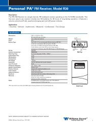
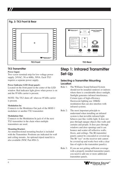
Fig. 3: TX3 Front & Rear<br />
<strong>Williams</strong> <strong>Sound</strong> ®<br />
Helping People Hear<br />
Omnimount<br />
25-STXMP<br />
For Ceiling Mount<br />
Infrared Transmitter<br />
Model WIR TX3<br />
Power Supply Wiring:<br />
Use NEC, Class 2 Wiring,<br />
18 ga. Min<br />
200 ft. Max. Length (18 ga.)<br />
Internal Fuse:<br />
1.25 A, 250V, 3AG<br />
Modulation Signal Wiring:<br />
Use RG59U Coax,<br />
1000 ft. Max. Length<br />
Omnimount<br />
25-STXMP<br />
For Wall Mount<br />
Note: It is normal for this unit<br />
to feel warm while it is in<br />
operation.<br />
CAUTION<br />
(75 Ohm)<br />
Modulation In<br />
(75 Ohm)<br />
24 VAC Power In,<br />
50-60 Hz, 35W<br />
<strong>Williams</strong> <strong>Sound</strong> Corp., Minneapolis, Minnesota, USA<br />
Made in U.S.A.<br />
<strong>Williams</strong> <strong>Sound</strong> ®<br />
Helping People Hear<br />
TX3 Transmitter<br />
Power Input:<br />
Two–screw terminal strip for low-voltage power<br />
supply. 24VAC, 50 or 60Hz, 50VA. Each TX3<br />
requires a separate power supply.<br />
Power Indicator LED (front panel):<br />
Located on the front panel in the center of the LED<br />
window. Red indicator light glows when power is on<br />
and the 95 kHz carrier is present.<br />
NOTE: The TX3 shuts off when no 95 kHz carrier<br />
is present.<br />
Modulation In:<br />
Connects to the Modulator Out jack of the MOD 1<br />
modulator or another TX3 transmitter.<br />
Modulation Out:<br />
Connects to the Modulation In jack of of the next<br />
TX3 transmitter in the chain when multiple<br />
transmitters are used.<br />
Mounting Bracket:<br />
An omnidirectional mounting bracket is included<br />
with the Transmitter. Positions are indicated for wall<br />
and ceiling mounts. An optional tripod stand kit is<br />
also available (WSC Part #SS-2).<br />
6<br />
TX3 Front<br />
TX3 Rear<br />
Step 1: Infrared Transmitter<br />
Set-Up<br />
Selecting a Transmitter Mounting<br />
Location<br />
Rule 1: The <strong>Williams</strong> <strong>Sound</strong> Infrared System<br />
should not be installed outdoors or indoors<br />
where there is considerable direct sunlight.<br />
Sunlight generates infrared interference.<br />
Certain types of high-efficiency<br />
fluorescent lighting use 100kHz<br />
modulation that can also interfere with<br />
infrared systems.<br />
Rule 2: The most important principle to<br />
understand when installing an infrared<br />
system is that invisible infrared light<br />
behaves just like visible light. It does not<br />
pass through opaque objects like walls and<br />
curtains and people. It does pass through<br />
windows and door openings and it can<br />
bounce and scatter off reflective walls,<br />
floors, and ceilings. The IR transmitter<br />
panels cannot be concealed or covered up.<br />
The IR “eye” on the receiver unit cannot<br />
be covered up and works best with a clear<br />
line-of-sight to the transmitter panel(s).<br />
Rule 3: If you are not getting sufficient coverage<br />
with a properly installed transmitter panel,<br />
you need to add one or more additional<br />
transmitter panels.<br />
<strong>Williams</strong> <strong>Sound</strong> ®<br />
Helping People Hear