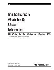
Installation Guide & User Manual - Williams Sound
Installation Guide & User Manual - Williams Sound
Installation Guide & User Manual - Williams Sound

You also want an ePaper? Increase the reach of your titles
YUMPU automatically turns print PDFs into web optimized ePapers that Google loves.
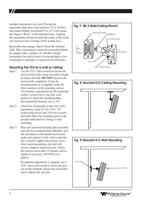
multiple transmitters are used. Placing the<br />
transmitter high above the audience (15 to 30 feet)<br />
and aimed slightly downward (5 to 15°) will ensure<br />
the longest “throw” of the infrared beam. Angling<br />
the transmitter inward towards the center of the room<br />
also increases the coverage of the seating area.<br />
Fig. 7: SB-3 Wall/Ceiling Mount<br />
Mounting Plate<br />
Ballshaft<br />
Clamp Plate<br />
Remember that opaque objects block the infrared<br />
light. Thus, transmitters cannot be concealed behind<br />
an opaque walls, curtains, etc. Neither should<br />
transmitters be used in areas of extreme high or low<br />
temperatures, humidity, or chemical environments.<br />
To<br />
Wall<br />
Or<br />
Ceiling<br />
Jaw<br />
To<br />
Transmitter<br />
Mounting the TX3 to a wall or ceiling:<br />
Step 1: Use the 5/32" allen wrench to loosen the<br />
tension bolt in the clamp assembly enough<br />
to release the ball. DO NOT unscrew the<br />
tension bolt completely. Using the<br />
mounting plate as a template, mark the<br />
hole locations on the mounting surface.<br />
Use fasteners appropriate for the mounting<br />
surface (wood screws, lag bolt, wall<br />
anchor) to attach the mounting plate.<br />
Recommended fastener size is 1/4".<br />
Step 2: Attach the clamp plate to the rear of the<br />
transmitter, using (2) 1/4 x 20 x 1/2"<br />
socket head screws and 3/16 hex wrench<br />
provided. Place the mounting plate in the<br />
position indicated for ceiling or wall<br />
mounting.<br />
Step 3: Place the transmitter/clamp plate assembly<br />
onto the the mounting plate ballshaft. Aim<br />
the transmitter at the desired downward<br />
angle and support it fully while using the<br />
hex wrench to tighten the tension screw.<br />
After initial installation, the ball will<br />
slowly compress under pressure. Check<br />
the tension screw after 15 minutes and retighten<br />
if necessary. DO NOT overtighten.<br />
If rotational adjustment is required, use a<br />
7/16" open-end wrench to loosen the jam<br />
nut on the ballshaft. Rotate the transmitter<br />
and re-tighten the jam nut.<br />
Tension Screw<br />
Fig. 8: Bracket 012 Ceiling Mounting<br />
Fig. 9: Bracket 012 Wall Mounting<br />
Jam Nut<br />
Front of TX3<br />
8<br />
<strong>Williams</strong> <strong>Sound</strong> ®<br />
Helping People Hear