Installation Guide & User Manual - Williams Sound
Installation Guide & User Manual - Williams Sound
Installation Guide & User Manual - Williams Sound

Create successful ePaper yourself
Turn your PDF publications into a flip-book with our unique Google optimized e-Paper software.
Step 3: 95 kHz Carrier<br />
Cable <strong>Installation</strong><br />
Step 1:<br />
Step 2:<br />
Step 3:<br />
Determine the length of RG59 coaxial<br />
cable needed to reach from the transmitter<br />
to the modulator unit. The modulator is<br />
usually located near the other sound<br />
equipment to simplify audio connections.<br />
100 feet of coaxial cable is included with<br />
each transmitter. You will need to cut it to<br />
length and install F-connectors on both<br />
ends. Additional RG59 coax can be added,<br />
up to 1000 feet maximum. Make sure you<br />
leave some slack at each end.<br />
Install the F-connectors on each end of the<br />
cable. You will need a CATV-type coax<br />
stripper and crimper.<br />
Connect the 95 kHz carrier cable to either<br />
Modulator Out jack on the MOD 1<br />
modulator and to the Modulator In jack on<br />
the TX3 transmitter.<br />
If you are using more than one transmitter:<br />
Step 1: Determine the length of coaxial cable<br />
needed to reach between the transmitters.<br />
100 feet of coaxial cable is included with<br />
each transmitter. You will need to cut it to<br />
length and install F-connectors on both<br />
ends. Additional RG59 coax can be added,<br />
up to 1000 feet maximum. Make sure you<br />
leave some slack at each end.<br />
Step 2: Install the F-connectors on each end of the<br />
cable. You will need a CATV-type coax<br />
stripper and crimper.<br />
Step 3:<br />
Connect the modulation cable from the<br />
Modulation Out Jack on the first<br />
transmitter in the chain (the one connected<br />
to the MOD 1 Modulator) to the<br />
Modulation In jack on the next TX3<br />
transmitter in the chain. Use the cable<br />
clamps and screws provided to secure the<br />
cable. The coax can also be routed through<br />
conduit. You can chain as many<br />
transmitters together as you need.<br />
Remember that each transmitter needs its<br />
own power supply.<br />
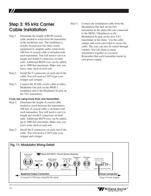
Fig. 11: Modulator Wiring Detail<br />
Made in USA<br />
Audio Input<br />
Balanced<br />
Mic<br />
Input Level<br />
Line<br />
Model WIR MOD1 Infrared System Modulator<br />
70V<br />
Audio Inputs<br />
Unbalanced<br />
Left<br />
Right<br />
Hi-Pass Filter<br />
175 Hz<br />
20 Hz 725 Hz<br />
6dB/octave<br />
<strong>Williams</strong> <strong>Sound</strong> Corp.<br />
Modulator<br />
Out<br />
75 Ohm<br />
Modulator<br />
Out<br />
75 Ohm<br />
Power: 24 VAC,<br />
50-60 Hz, 10VA<br />
Plug<br />
Power: 24 VAC, 60 Hz, 50VA<br />
Baseband Output Connection<br />
Connect to TX3 here using RG-59 cable.<br />
Power Connection<br />
Plug in Power Supply<br />
10<br />
<strong>Williams</strong> <strong>Sound</strong> ®<br />
Helping People Hear