Analysis for buckling and vibrations of composite ... - ResearchGate
Analysis for buckling and vibrations of composite ... - ResearchGate
Analysis for buckling and vibrations of composite ... - ResearchGate

You also want an ePaper? Increase the reach of your titles
YUMPU automatically turns print PDFs into web optimized ePapers that Google loves.
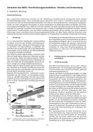
Composite Structures 51 (2001) 361±370<br />
www.elsevier.com/locate/compstruct<br />
<strong>Analysis</strong> <strong>for</strong> <strong>buckling</strong> <strong>and</strong> <strong>vibrations</strong> <strong>of</strong> <strong>composite</strong> sti€ened shells <strong>and</strong><br />
plates<br />
R. Rikards * , A. Chate, O. Ozolinsh<br />
Institute <strong>of</strong> Computer <strong>Analysis</strong> <strong>of</strong> Structures, Faculty <strong>of</strong> Civil Engineering, Riga Technical University, Kalku St. 1, LV-1658 Riga, Latvia<br />
Abstract<br />
This paper deals with development <strong>of</strong> triangular ®nite element <strong>for</strong> <strong>buckling</strong> <strong>and</strong> vibration analysis <strong>of</strong> laminated <strong>composite</strong><br />
sti€ened shells. For the laminated shell, an equivalent layer shell theory is employed. The ®rst-order shear de<strong>for</strong>mation theory<br />
including extension <strong>of</strong> the normal line is used. In order to take into account a non-homogeneous distribution <strong>of</strong> the transverse shear<br />
stresses a correction <strong>of</strong> transverse shear sti€ness is employed. Based on the equivalent layer theory with six degrees <strong>of</strong> freedom (three<br />
displacements <strong>and</strong> three rotations), a ®nite element that ensures C 0 continuity <strong>of</strong> the displacement <strong>and</strong> rotation ®elds across interelement<br />
boundaries has been developed. Numerical examples are presented to show the accuracy <strong>and</strong> convergence characteristics <strong>of</strong><br />
the element. Results <strong>of</strong> vibration <strong>and</strong> <strong>buckling</strong> analysis <strong>of</strong> sti€ened plates <strong>and</strong> shells are discussed. Ó 2001 Elsevier Science Ltd. All<br />
rights reserved.<br />
Keywords: Finite element; Sti€ened shells; Vibrations; Buckling<br />
1. Introduction<br />
Due to their high speci®c modulus compared to<br />
metallic material, laminated <strong>composite</strong> materials o€er<br />
more ecient structures <strong>for</strong> application in aerospace<br />
engineering. Aerospace structures such as wings or fuselages<br />
are mostly assemblies <strong>of</strong> shell structures. In<br />
general, <strong>composite</strong> shell ®nite elements are based on the<br />
same shell theories as <strong>for</strong> conventional materials.<br />
However, there are some di€erences, which will be<br />
outlined below.<br />
Many curved shell ®nite element <strong>for</strong>mulations have<br />
been developed <strong>and</strong> reported in the literature. A selected<br />
number <strong>of</strong> textbooks are given in [1±4]. Rather complete<br />
bibliography can be found in reviews [5,6].<br />
Since laminated <strong>composite</strong>s have a low transverse<br />
sti€ness shell theories accounting transverse shear de<strong>for</strong>mations<br />
should be used. These are the so-called re-<br />
®ned shell theories [7,8]. For analysis <strong>of</strong> laminated<br />
structures, three main approaches can be employed.<br />
1. Approach based on a single layer theory.<br />
2. Approach based on equivalent layer theory.<br />
3. Approach based on layerwise theory.<br />
* Corresponding author. Tel.: +371-708-9264; fax: +371-782-0094.<br />
E-mail address: rikards@latnet.lv (R. Rikards).<br />
The ®rst approach based on single layer theory is<br />
applied <strong>for</strong> the homogeneous in transverse directions<br />
structures consisting <strong>of</strong> one layer. In this case, the approximation<br />
<strong>of</strong> displacements are per<strong>for</strong>med throughout<br />
the thickness <strong>of</strong> shell. The second approach (equivalent<br />
layer theories) is employed <strong>for</strong> multilayered shells. In<br />
this case, the approximations are also per<strong>for</strong>med <strong>for</strong> the<br />
whole stack <strong>of</strong> layers, but in addition it is necessary to<br />
per<strong>for</strong>m some corrections <strong>of</strong> the transverse sti€ness.<br />
However, ®nally the laminated structure is considered as<br />
one equivalent layer. In the third approach (layerwise<br />
theories), the approximations are per<strong>for</strong>med <strong>for</strong> each<br />
layer <strong>of</strong> the laminated structure. In this case, an interlayer<br />
continuity condition as well as top <strong>and</strong> bottom<br />
surface boundary conditions <strong>for</strong> the displacements <strong>and</strong><br />
stresses are used.<br />
Re®ned theories are based on higher order approximations<br />
<strong>of</strong> the displacements. Higher order approximations<br />
<strong>for</strong> beams, plates <strong>and</strong> shells were introduced<br />
starting with investigations <strong>of</strong> Timoshenko [9], Reissner<br />
[10], Hencky [11], Mindlin [12], Naghdi [13] <strong>and</strong> other<br />
researchers. A general ®rst-order shear de<strong>for</strong>mation<br />
theory <strong>for</strong> small de¯ections <strong>and</strong> small rotations <strong>of</strong> the<br />
shell was outlined by Naghdi [14]. A general non-linear<br />
theory <strong>of</strong> shells <strong>for</strong> large de¯ections <strong>and</strong> large rotations<br />
including transverse shear de<strong>for</strong>mations <strong>and</strong> extension<br />
<strong>of</strong> the normal line was developed by Galimov [15] <strong>and</strong><br />
later by other authors.<br />
0263-8223/01/$ - see front matter Ó 2001 Elsevier Science Ltd. All rights reserved.<br />
PII: S 0 2 6 3 - 8 2 2 3 ( 0 0 ) 0 0 151-3
362 R. Rikards et al. / Composite Structures 51 (2001) 361±370<br />
There is extensive literature <strong>for</strong> analysis <strong>of</strong> sti€ened<br />
plates <strong>and</strong> shells. For example, review <strong>and</strong> analysis <strong>of</strong><br />
<strong>buckling</strong> problems <strong>of</strong> sti€ened plates are presented in<br />
[16]. The eciency <strong>of</strong> the ®nite element method in<br />
comparison with other methods <strong>for</strong> analysis <strong>of</strong> sti€ened<br />
structures was shown.<br />
In the present paper, the equivalent layer theory<br />
based on the ®rst-order shear de<strong>for</strong>mation theory including<br />
extension <strong>of</strong> normal line (FOSDT-6) is employed<br />
in order to develop the ®nite element <strong>for</strong> analysis<br />
<strong>of</strong> laminated sti€ened shells. Previously, similar ®nite<br />
element was developed <strong>and</strong> applied <strong>for</strong> analysis <strong>of</strong><br />
smooth shells [17,18].<br />
2. Kinematics <strong>of</strong> shell<br />
Kinematic equations <strong>for</strong> the ®rst-order shear de<strong>for</strong>mation<br />
theory (FOSDT) including extension <strong>of</strong> the<br />
normal line can be obtained from the 3D equations <strong>of</strong><br />
the theory <strong>of</strong> elasticity by using a well-known ®rst-order<br />
approximation <strong>of</strong> a vector function with respect to the<br />
coordinate x 3 . Further a well-known geometric relations<br />
<strong>for</strong> the shell in normal coordinates (see, <strong>for</strong> example,<br />
[14]) are used.<br />
Let us assume that vector r characterizes the position<br />
<strong>of</strong> an arbitrary point <strong>of</strong> the shell in the initial reference<br />
state (see point B in Fig. 1) <strong>and</strong> vector R is the position<br />
<strong>of</strong> the same point (point B 0 ) in the de<strong>for</strong>med state. The<br />
position <strong>of</strong> a point at the midsurface <strong>of</strong> the shell (point<br />
A) in the initial state is characterized by vector r, <strong>and</strong><br />
position <strong>of</strong> the same point in the de<strong>for</strong>med state (point<br />
A 0 ) is characterized by vector R. Normal curvilinear<br />
coordinates x i ˆ‰x a ; x 3 Š at the midsurface <strong>of</strong> the shell in<br />
the initial state are de®ned by the right-h<strong>and</strong>ed triad <strong>of</strong><br />
the base vectors ‰a a ; a 3 Š. Here, a unit vector a 3 is normal<br />
to the midsurface <strong>of</strong> shell. There<strong>for</strong>e (see Fig. 1)<br />
r…x i †ˆr…x a †‡x 3 a 3 :<br />
…1†<br />
Similarly, curvilinear coordinates X i ˆ‰X a ; X 3 Š in the<br />
de<strong>for</strong>med state is de®ned by the triad <strong>of</strong> vectors ‰A a ; A 3 Š.<br />
Fig. 1. Kinematics <strong>of</strong> the ®rst-order shear de<strong>for</strong>mation theory.<br />
In the de<strong>for</strong>med state, the vector A 3 may be not perpendicular<br />
to the midsurface <strong>of</strong> shell.<br />
Vector function R can be exp<strong>and</strong>ed in a Taylor's series<br />
with respect to coordinate x 3 normal to the midsurface<br />
<strong>of</strong> shell<br />
R…x i †ˆR…x a †‡x 3 rR a 3 ‡<br />
…2†<br />
Here rR ˆ A a a a ˆ G is a second-order tensor<br />
(see, <strong>for</strong> example, [19]), which characterizes the gradient<br />
<strong>of</strong> strains with respect to coordinate x 3 , r is a Hamiltonian<br />
operator, <strong>and</strong> is a dyadic product <strong>of</strong> the tensors.<br />
Further, the notations <strong>for</strong> displacement at the midsurface<br />
v <strong>and</strong> displacement <strong>of</strong> an arbitrary point <strong>of</strong> shell<br />
u are introduced. The following expressions can be<br />
written (see Fig. 1)<br />
R ˆ r ‡ u; R ˆ r ‡ v: …3†<br />
From expressions (1)±(3) the representation <strong>of</strong> the displacement<br />
u <strong>of</strong> an arbitrary point <strong>of</strong> the shell <strong>for</strong> the<br />
®rst-order approximation can be obtained<br />
u…x a †ˆv…x a †‡x 3 c…x a †:<br />
…4†<br />
Here c is vector <strong>of</strong> rotation at the midsurface <strong>of</strong> shell<br />
c…x a †ˆA 3 …x a †a 3 …x a †;<br />
…5†<br />
where<br />
A 3 ˆ G a 3 :<br />
…6†<br />
In expression (4), the vectors v <strong>and</strong> c each have three<br />
components<br />
v ˆ v a a a ‡ wa 3 ; c ˆ c a a a ‡ ca 3 : …7†<br />
The motion <strong>of</strong> the shell is completely described by the<br />
two vectors, the displacement vector v <strong>and</strong> the rotation<br />
vector c. There<strong>for</strong>e, the displacement ®eld <strong>of</strong> the shell in<br />
the FOSDT including extension <strong>of</strong> the normal line is<br />
represented by six unknown functions ± three displacements<br />
(v a ; w) <strong>and</strong> three rotations (c a ; c). These quantities<br />
are only functions <strong>of</strong> the shell midsurface coordinates x a .<br />
From displacements <strong>and</strong> rotations, the two-dimensional<br />
strains can be obtained.<br />
A three-dimensional Green's strain tensor in the linear<br />
case (in®nitesimal strain theory) is given by (see, <strong>for</strong><br />
example, [20])<br />
2e ij ˆ u ;i g j ‡ u ;j g i :<br />
…8†<br />
Here, partial di€erentiation is denoted by a comma<br />
…† ;i<br />
o=ox i <strong>and</strong> g i is a triad <strong>of</strong> base vectors <strong>for</strong> the<br />
spatial coordinates x i at the surfaces (x 3 ˆ const:) parallel<br />
to the midsurface (reference surface) <strong>of</strong> shell. The<br />
metric tensor <strong>of</strong> the spatial system is given by g ij ˆ g i g j<br />
<strong>and</strong> the metric properties <strong>of</strong> the midsurface are characterized<br />
by a ab ˆ a a a b . Substituting the approximation<br />
(4) into Eq. (8) the strain displacement relations can be<br />
obtained in a routine way (see, <strong>for</strong> example, [14]). From<br />
these strain displacement relations, kinematic equations
in di€erent curvilinear coordinates can be obtained <strong>and</strong><br />
written through the physical components in the matrix<br />
<strong>for</strong>m<br />
ˆ Lw:<br />
…9†<br />
Here w is physical components <strong>of</strong> vectors <strong>of</strong> displacement<br />
v <strong>and</strong> rotation c<br />
w T ˆ‰u; v; w; c …1† ; c …2† ; cŠ:<br />
R. Rikards et al. / Composite Structures 51 (2001) 361±370 363<br />
…10†<br />
The shell theory outlined above is the so-called ®rstorder<br />
shear de<strong>for</strong>mation theory with six degrees <strong>of</strong><br />
freedom (FOSDT-6). Note, that in the present theory<br />
the normal line undergoes a small rotation relative to<br />
the reference surface <strong>and</strong> also a small, uni<strong>for</strong>m extension.<br />
The third component <strong>of</strong> the vector c, i.e., the<br />
function c ˆ c…x a † characterizes the de<strong>for</strong>mation in the<br />
direction <strong>of</strong> normal line. Often this de<strong>for</strong>mation is neglected<br />
c ˆ 0. Thus, the ®rst-order shear de<strong>for</strong>mation<br />
theory with ®ve degrees <strong>of</strong> freedom (FOSDT-5) can be<br />
obtained. In the case <strong>of</strong> ¯exural de<strong>for</strong>mation <strong>of</strong> plates<br />
with symmetric layer stacking sequence the in-plane<br />
displacements u ˆ 0 <strong>and</strong> v ˆ 0. There<strong>for</strong>e, <strong>for</strong> analysis<br />
<strong>of</strong> such plates the ®rst-order shear de<strong>for</strong>mation theory<br />
with three degrees <strong>of</strong> freedom (FOSDT-3) can be employed.<br />
3. Strain energy <strong>and</strong> sti€ness <strong>of</strong> laminated shell<br />
The strain energy U <strong>of</strong> the shell represented as a<br />
three-dimensional body is given by the expression,<br />
where in curvilinear coordinates the contravariant stress<br />
tensor r ij is contracted with the covariant strain tensor<br />
e ij<br />
U ˆ 1 Z<br />
r ij e ij dV ;<br />
2 V<br />
where dV is a volume element <strong>of</strong> the shell<br />
dV ˆ<br />
dA ˆ<br />
p g dx 1 dx 2 dx 3 ˆ<br />
p a dx 1 dx 2 :<br />
r<br />
g<br />
dx 3 dA;<br />
a<br />
…11†<br />
…12†<br />
Here dA is the shell midsurface element <strong>and</strong> a determinants<br />
<strong>of</strong> the metric tensors are given by a ˆ det…a ab † <strong>and</strong><br />
g ˆ det…g ij †.<br />
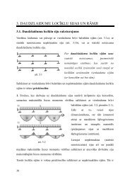
In the laminated structures, the sti€ness properties<br />
are function <strong>of</strong> the normal coordinate. In Fig. 2, a crosssection<br />
<strong>of</strong> laminated shell composed <strong>of</strong> K layers is presented.<br />
The thickness <strong>of</strong> the kth layer is h k , the inner<br />
coordinate <strong>of</strong> the ®rst layer is x …0†<br />
3<br />
, the coordinate at the<br />
interface <strong>of</strong> the ®rst <strong>and</strong> the second layer is denoted by<br />
x …1†<br />
3<br />
, etc. A linear elastic properties <strong>of</strong> the anisotropic<br />
layers are characterized by the tensor <strong>of</strong> elasticity A.<br />
This tensor is function <strong>of</strong> the coordinate x 3 , i.e.,<br />
A ˆ A…x 3 †.<br />
Fig. 2. Cross-section <strong>of</strong> laminated shell composed <strong>of</strong> K layers.<br />
In many applications, it can be assumed that calculations<br />
<strong>of</strong> shell sti€ness properties can be per<strong>for</strong>med<br />
neglecting the di€erences in spatial <strong>and</strong> shell midsurface<br />
metrics, i.e., a ab g ab . In this case, the Hooke's law <strong>for</strong><br />
each layer can be written by<br />
r ij ˆ A ijkl e kl :<br />
…13†<br />
Here A ijkl is the component <strong>of</strong> the elasticity tensor in the<br />
midsurface metrics. Substituting Eq. (13) into (11) <strong>and</strong><br />
taking into account the relations (12) the strain energy U<br />
can be expressed by<br />
Z Z h=2<br />
U ˆ A ijkl e ij e kl dx 3 dA:<br />
…14†<br />
A<br />
h=2<br />
After integration, throughout the thickness, the strain<br />
energy can be obtained in terms <strong>of</strong> shell quantities: stress<br />
resultants <strong>and</strong> couples <strong>and</strong> laminated shell sti€ness<br />
characteristics<br />
…Q abcd ; B abcd ; D abcd †ˆ<br />
Z h=2<br />
h=2<br />
A abcd …1; x 3 ; x 2 3 † dx 3;<br />
Z h=2<br />
Q a3b3 ˆ c …a3† A a3b3 dx 3 :<br />
h=2<br />
…15†<br />
Here c …a3† are shear correction coecients. These shear<br />
correction coecients must be used <strong>for</strong> laminated shells<br />
<strong>for</strong> more correct representation <strong>of</strong> the transverse shear<br />
sti€ness properties. Calculation <strong>of</strong> the shear correction<br />
coecients can be per<strong>for</strong>med by using various methods.<br />
Some approaches have been discussed in [21±23]. Further<br />
in numerical examples the matrix notations <strong>for</strong> the<br />
shear correction coecients are used.<br />
k 2 4 ˆ c …23†; k 2 5 ˆ c …13†:<br />
Since the elastic properties are to be constant throughout<br />
the layer thickness the expressions (15) can be easily<br />
integrated
364 R. Rikards et al. / Composite Structures 51 (2001) 361±370<br />
Q abcd ˆ XK<br />
B abcd ˆ 1<br />
2<br />
kˆ1<br />
X K<br />
kˆ1<br />
A abcd<br />
…k†<br />
‰x 3…k† x 3…k1† Š;<br />
A abcd<br />
…k†<br />
‰x 2 3…k† x2 3…k1† Š;<br />
D abcd ˆ 1 X K<br />
A abcd<br />
…k†<br />
‰x 3 3…k†<br />
3<br />
x3 3…k1† Š;<br />
kˆ1<br />
Q a3b3 ˆ c …a3†<br />
X K<br />
Here A ijkl<br />
…k†<br />
kth layer.<br />
kˆ1<br />
4. Finite elements<br />
A a3b3<br />
…k†<br />
‰x 3…k† x 3…k1† Š:<br />
…16†<br />
are components <strong>of</strong> the elasticity tensor <strong>of</strong> the<br />
In [17] <strong>for</strong> the shell analysis, it was proposed to use<br />
two ®nite elements based on FOSDT-5 (see Fig. 3). The<br />
®rst element with six nodes called SH30 is based on the<br />
second-order approximation <strong>of</strong> displacements. The second<br />
element with 10 nodes called SH50 is based on the<br />
third-order approximation <strong>of</strong> displacements. Since the<br />
element SH50 has internal node <strong>and</strong> is too complicated,<br />
further only the quadratic element was developed [18].<br />
However, the cubic element has higher convergence rate<br />
[17].<br />
For sti€ened shells, two di€erent shell surfaces should<br />
be assembled. In this case, in order to obtain a continuous<br />
displacement <strong>and</strong> rotation ®elds the FOSDT-6<br />
should be used. The displacements (10) are approximated<br />
by the second-order polynomial shape functions<br />
(see [1])<br />
w T ˆ‰N 1 I; N 2 I; ...; N 6 IŠv e ˆ Nv e :<br />
…17†<br />
Here I is a 6 6 unity matrix <strong>for</strong> the FOSDT-6, a 5 5<br />
unity matrix <strong>for</strong> the FOSDT-5 <strong>and</strong> a 3 3 unity matrix<br />
<strong>for</strong> the FOSDT-3. For the FOSDT-6, the element displacement<br />
vector v e is given by<br />
v T e ˆ‰ve 1 ; ve 2 ; ...; ve 6 Š;<br />
v eT<br />
i<br />
ˆ‰u i ; v i ; w i ; c i …1† ; ci …2† ; c iŠ:<br />
…18†<br />
Here v e i<br />
…i ˆ 1; 2; ...; 6† are displacements <strong>for</strong> the ith<br />
node. For the FOSDT-5, the element displacement<br />
vector in Eq. (17) is given by<br />
v T e ˆ ve 1 ; ve 2 ; ...; h<br />
i<br />
ve 6 ; v<br />
eT<br />
i<br />
ˆ u i ; v i ; w i ; c i …1† ; ci …2†<br />
: …19†<br />
For the FOSDT-3, the element displacement vector in<br />
Eq. (17) is given by<br />
v T e ˆ ve 1 ; ve 2 ; ...; h i<br />
ve 6 ; v<br />
eT<br />
i<br />
ˆ w i ; c i …1† ; ci …2†<br />
: …20†<br />
There<strong>for</strong>e, at all three triangular ®nite elements <strong>for</strong><br />
analysis <strong>of</strong> shells <strong>and</strong> plates are considered.<br />
1. The ®nite element SH36 based on second-order approximation<br />
<strong>of</strong> displacements according the FOS-<br />
DT-6.<br />
2. The ®nite element SH30 based on second-order approximation<br />
<strong>of</strong> displacements according the FOS-<br />
DT-5.<br />
3. The ®nite element PL18 based on second-order approximation<br />
<strong>of</strong> displacements according the FOS-<br />
DT-3.<br />
Here, the plate element PL18 is considered only <strong>for</strong><br />
the convergence studies.<br />
For discretization <strong>of</strong> the sti€ened structures, several<br />
idealizations can be used in which the assemblies can be<br />
treated as collections <strong>of</strong> the shell, plate <strong>and</strong> beam elements.<br />
The sti€eners depending on dimensions can be<br />
idealized as a shell or beam elements. For light sti€eners,<br />
the overall (global) <strong>buckling</strong> or vibration modes occur<br />
<strong>and</strong> in this case the beam elements can be used. If the<br />
sti€ener is ¯exurally <strong>and</strong> rotationally sti€ <strong>and</strong> skin <strong>of</strong> the<br />
shell is thin, then the local mode <strong>of</strong> the skin is dominant.<br />
In this case <strong>for</strong> sti€eners also the beam elements can be<br />
used. In the case <strong>of</strong> torsionally weak sti€ener, a local<br />
<strong>buckling</strong> occurs in the sti€ener. In this case, the sti€ener<br />
should be idealized by using the shell (plate) elements.<br />
There<strong>for</strong>e, the idealization depends upon the geometric<br />
characteristics <strong>of</strong> the attached sti€ener.<br />
In order to reduce the degrees <strong>of</strong> freedom <strong>of</strong> assembled<br />
structure <strong>for</strong> some geometric dimensions <strong>of</strong> sti€ener<br />
a spatial beam elements can be used. Let us consider the<br />
spatial beam element compatible with the shell ®nite<br />
element SH36. So, <strong>for</strong> the beam a second-order approximation<br />
<strong>of</strong> displacements <strong>and</strong> rotations should be<br />
used. A beam element with three nodes is presented in<br />
Fig. 4. For the present element a Timoshenko's beam<br />
theory is used to derive the element matrices. In addition<br />
a torsional de<strong>for</strong>mation <strong>of</strong> the beam is taken into<br />
Fig. 3. Isoparametric triangular ®nite elements with six (a) <strong>and</strong> 10 (b)<br />
nodes. Fig. 4. Spatial Timoshenko's beam ®nite element B18.
R. Rikards et al. / Composite Structures 51 (2001) 361±370 365<br />
account. So, the beam displacement vector is the same as<br />
<strong>for</strong> shell Eq. (10) <strong>and</strong> the element displacement vector is<br />
given by<br />
v T e ˆ‰ve 1 ; ve 2 ; ve 3 Š;<br />
h<br />
veT i<br />
ˆ u i ; v i ; w i ; c i …1† ; ci …2† ; c i<br />
i<br />
: …21†<br />
At all <strong>for</strong> the present beam element there are 18 DOF<br />
<strong>and</strong> the element is designated as B18. Similar Timoshenko's<br />
beam ®nite element employing the third-order<br />
approximations was developed in [24].<br />
The ®nite elements SH36 <strong>and</strong> B18 can be used to<br />
assemble the sti€ened shells <strong>of</strong> an arbitrary shape since<br />
<strong>for</strong> both isoparametric elements the mapping technique<br />
is applied. The locking phenomenon <strong>for</strong> these elements<br />
can be avoided by using a selective integration technique<br />
[25].<br />
5. Numerical examples<br />
Further the vibration <strong>and</strong> <strong>buckling</strong> problems <strong>of</strong><br />
di€erent structures are analyzed. In order to evaluate<br />
the natural frequencies a linear eigenvalue problem is<br />
solved<br />
Ku kMu ˆ 0:<br />
…22†<br />
Here K <strong>and</strong> M is a global sti€ness <strong>and</strong> mass matrices, u<br />
is global displacement vector <strong>and</strong> k ˆ x 2 , where x ˆ<br />
2pf is a circular frequency <strong>and</strong> f is a frequency. The<br />
subspace iteration method [26], which is widely used <strong>for</strong><br />
large scale ®nite element calculations, is employed to<br />
solve Eq. (22).<br />
Di€erent methods are employed to estimate <strong>buckling</strong><br />
loads. The simplest is linearized <strong>buckling</strong> analysis, where<br />
Fig. 5. Geometry <strong>of</strong> laminated plate.<br />
the critical load parameter k can be estimated by solving<br />
the equation<br />
Ku kGu ˆ 0:<br />
…23†<br />
Here G is a geometric sti€ness matrix.<br />
5.1. Convergence study <strong>of</strong> ®nite element PL18<br />
Let us study the convergence properties <strong>of</strong> the element<br />
PL18 <strong>for</strong> the vibration problem <strong>of</strong> square plate.<br />
The vibration problem is solved employing Eq. (22). For<br />
this a consistent mass matrix M should be derived, i.e.,<br />
the same shape functions should be used to develop the<br />
sti€ness <strong>and</strong> mass matrices.<br />
The error estimates <strong>for</strong> the linear ®nite element<br />
problems are given in [1,27]. If within an element <strong>of</strong> size<br />
h a polynomial approximation <strong>of</strong> degree k 1 is employed<br />
<strong>and</strong> the higher derivative <strong>of</strong> the displacements in<br />
the functional to be minimized is m, the error <strong>of</strong> the<br />
strain energy is O…h 2…km† †. There<strong>for</strong>e, <strong>for</strong> the quadratic<br />
elements (SH36, PL18 or B18) these numbers are as<br />
follows …k ˆ 3; m ˆ 1† <strong>and</strong> the error estimate <strong>for</strong> the<br />
strain energy is O…h 4 †. The same error estimate is <strong>for</strong> the<br />
eigenvalues <strong>of</strong> the Eq. (22). Note that element size is<br />
inversely proportional to the number <strong>of</strong> ®nite elements<br />
per side <strong>of</strong> the plate h N 1 .<br />
Let us consider a square cross-ply plate with layer<br />
stacking sequence [0/90/0] (see Fig. 5). The ®bers <strong>of</strong> the<br />
top <strong>and</strong> bottom layers is in direction <strong>of</strong> x-axis. This<br />
example was examined using the re®ned plate theory in<br />
[28] <strong>and</strong> by employing a 3D elasticity solution in [29].<br />
The plate parameters are as follows:<br />
a ˆ b ˆ 5; h ˆ 1; E 1 ˆ 40; E 2 ˆ 1;<br />
G 12 ˆ G 13 ˆ 0:6; G 23 ˆ 0:5; m 12 ˆ 0:25; q ˆ 1:<br />
The unidirectionally rein<strong>for</strong>ced layers are to be transverselly<br />
isotropic, where 1 is ®ber direction. The plate is<br />
simply supported <strong>and</strong> can be analyzed employing the<br />
following boundary conditions:<br />
v; w; c y j xˆ0;a ˆ 0; u; w; c x j yˆ0;b ˆ 0:<br />
Results <strong>for</strong> the ®rst natural frequency are presented in<br />
Table 1. The actual values <strong>of</strong> shear correction coecients<br />
<strong>of</strong> the present plate calculated by the approach<br />
outlined in [22] are k4 2 ˆ 0:827; k2 5 ˆ 0:521. In [28],<br />
the value k4 2 ˆ k2 5 ˆ 5=6 as <strong>for</strong> homogeneous plate was<br />
used.<br />
In Table 1 results are compared with a 3D elasticity<br />
solution, higher order shear de<strong>for</strong>mation plate theory<br />
(HSDPT) <strong>and</strong> classical plate theory (CPT). It should be<br />
Table 1<br />
p<br />
Non-dimensional ®rst frequency x ˆ x<br />
<br />
qh 2 =E 2 <strong>of</strong> the cross-ply plate<br />
3D elasticity [29] HSDPT [28] FOSDT [28] Present CPT<br />
0.4300 0.4315 0.4342 0.4229 0.7319
366 R. Rikards et al. / Composite Structures 51 (2001) 361±370<br />
Fig. 7. Geometry <strong>of</strong> the single ribbed plate.<br />
Fig. 6. Convergence study <strong>for</strong> the eigenvalue <strong>of</strong> vibrating plate.<br />
noted that result employing the present element PL18<br />
with k4 2 ˆ k2 5 ˆ 5=6 is x ˆ 0:4342, i.e., the same as<br />
reference solution by Reddy (FOSDT). Present results<br />
were obtained using the mesh 32 32 (N ˆ 32), i.e., the<br />
plate is divided in 2048 elements. This is a rather ®ne<br />
mesh <strong>and</strong> the result can be treated as exact.<br />
The numerical (FEM) <strong>and</strong> theoretical convergence<br />
graphs <strong>for</strong> the fourth eigenvalue k 4 are presented in<br />
Fig. 6. Results are presented in logarithmic scale <strong>and</strong><br />
numerical error is calculated by expression<br />
e ˆ j^k k exact j<br />
k exact<br />
:<br />
Here ^k is approximate (numerical) solution <strong>and</strong> k exact is<br />
exact solution (<strong>for</strong> the mesh 32 32). In Fig. 6, a slope<br />
<strong>of</strong> the theoretical error estimate O…N 4 † <strong>for</strong> the quadratic<br />
element are also presented in logarithmic scale. It<br />
is seen that <strong>for</strong> the element PL18 a convergence rate <strong>of</strong><br />
numerical solution is the same as theoretical error estimate.<br />
The element matrices are evaluated by using numerical<br />
integration. For plates, when the elements are ¯at<br />
triangles, it is easy to determine the order <strong>of</strong> numerical<br />
integration <strong>for</strong>mula, by which the strain energy can be<br />
exactly integrated. In this case, the order <strong>of</strong> polynomial<br />
which should be integrated is known. More complicated<br />
is the case <strong>of</strong> using the isoparametric ®nite elements. In<br />
this case, after discretization <strong>of</strong> the strain energy the<br />
rational functions should be integrated. Thus, the required<br />
order <strong>of</strong> integration <strong>for</strong>mula should be chosen<br />
empirically.<br />
5.2. Vibration <strong>of</strong> the isotropic sti€ened plate<br />
The <strong>vibrations</strong> <strong>of</strong> clamped isotropic plate with a<br />
single rib is examined (see Fig. 7). For the present single<br />
ribbed square plate, the experimental natural frequencies<br />
were measured in [30]. The plate parameters are as<br />
follows:<br />
a ˆ b ˆ 203 mm; h ˆ 1:37 mm; t s ˆ 6:35 mm;<br />
h s ˆ 12:7 mm; E ˆ 68:7 GPa; m ˆ 0:3;<br />
q ˆ 2820 kg=m 3 :<br />
Here a <strong>and</strong> b are the side lengths <strong>of</strong> the plate, h the plate<br />
thickness, t s the rib thickness, h s the rib depth, E the<br />
Young's modulus, m the Poisson's ratio <strong>and</strong> q is a density.<br />
The plate was assembled in two di€erent ways. The<br />
®rst assembly was created by using <strong>for</strong> the skin <strong>and</strong> rib<br />
the shell element SH36 (designated as shell model) <strong>and</strong><br />
the second by using the shell element <strong>for</strong> the skin <strong>and</strong><br />
beam element B18 <strong>for</strong> the rib (designated as beam<br />
model). Results <strong>for</strong> the 24 ®rst natural frequencies are<br />
presented in Table 2. Present results <strong>for</strong> both assemblies<br />
was obtained using the mesh 24 24. For the shell<br />
model, a lumped (diagonal) mass matrix was used. For<br />
the beam model, a consistent mass matrix was employed<br />
in Eq. (22). Experimental frequencies are taken from the<br />
paper [30]. For comparison numerical frequencies have<br />
also been calculated employing the code ANSYS. In this<br />
case, the mesh 24 24 was used <strong>and</strong> the assembly <strong>of</strong> the<br />
plate (shell) elements <strong>for</strong> the skin <strong>and</strong> rib was employed.<br />
From analysis <strong>of</strong> the results presented in Table 2, it is<br />
seen that the best agreement with the experiment is <strong>for</strong><br />
numerical frequencies calculated by ANSYS. At all 18<br />
frequencies are closer to the experiment than other<br />
predictions. Present analysis employing the beam model<br />
gives the best prediction <strong>for</strong> ®ve frequencies including<br />
the ®rst one. Present analysis using the shell model gives<br />
the best prediction <strong>for</strong> the frequency f 10 .<br />
Selected vibration mode shapes are presented in<br />
Fig. 8. Mode 1 is overall vibration mode, modes 12 <strong>and</strong><br />
24 are a local skin vibration modes <strong>and</strong> mode 20 is a<br />
coupled vibration mode with skin±rib interaction. In<br />
general, it can be concluded that <strong>for</strong> present geometric<br />
dimensions (rib <strong>of</strong> low aspect ratio h s =t s ) it is sucient to<br />
assemble the sti€ened plate by a compatible combination<br />
<strong>of</strong> beam <strong>and</strong> plate (shell) elements since such assembly<br />
can accurately predict the natural frequencies<br />
<strong>and</strong> mode shapes. Advantage <strong>of</strong> the beam model is also<br />
less DOF in comparison with assembly <strong>of</strong> shell elements<br />
only.
R. Rikards et al. / Composite Structures 51 (2001) 361±370 367<br />
Table 2<br />
Experimental <strong>and</strong> numerical frequencies [Hz] <strong>of</strong> single ribbed clamped plate<br />
Mode Ref. [30] ANSYS Present<br />
Theory Experiment Shell model Beam model Shell model<br />
1 718.1 689 712.6 693.2 722.8<br />
2 751.4 725 742.9 751 754.6<br />
3 997.4 961 983.8 984.8 997.9<br />
4 1007.1 986 993.6 1007 1009<br />
5 1419.8 1376 1398.5 1417 1425<br />
6 1424.3 1413 1402.5 1427 1430<br />
7 1631.5 1512 1599.5 1651 1690<br />
8 1853.9 1770 1831 1829 1866<br />
9 2022.8 1995 1983.6 2019 2027<br />
10 2025 2069 1985.8 2024 2029<br />
11 2224.9 2158 2175.6 2191 2227<br />
12 2234.9 2200 2185 2231 2240<br />
13 2400.9 2347 2344.6 2393 2423<br />
14 2653.9 2597 2585.9 2645 2671<br />
15 2670.2 2614 2597.5 2674 2683<br />
16 2802.4 2784 2733.9 2789 2800<br />
17 2804.6 2784 2735.1 2793 2802<br />
18 3259 3174 3143.7 3254 3276<br />
19 3265.9 3174 3148.8 3271 3283<br />
20 3414.2 3332 3316.8 3583 3403<br />
21 3754 3660 3644.3 3724 3741<br />
22 3754.8 3730 3644.8 3726 3741<br />
23 3985.5 3780 3798.8 3909 3950<br />
24 4045.9 3913 3862.9 4019 4054<br />
obtained <strong>for</strong> the clamped sti€ened plate made <strong>of</strong> a carbon/epoxy<br />
<strong>composite</strong> material (AS1/3501-6). The properties<br />
<strong>of</strong> that material are listed in Table 3. The layer<br />
stacking sequence <strong>of</strong> the skin plate is ‰0= 45=90Š s<br />
. The<br />
play thickness is 0.13 mm <strong>and</strong> at all in the skin there are<br />
eight layers. The rib is made from the cross-ply laminate<br />
with 28 layers. The layer stacking sequence throughout<br />
the rib thickness is ‰0 7 =90 7 Š s<br />
. The plate parameters are as<br />
follows (see Fig. 7).<br />
a ˆ 250 mm; b ˆ 500 mm; t p ˆ 1:04 mm;<br />
h s ˆ 10:5 mm; t s ˆ 3:64 mm:<br />
Fig. 8. Vibration modes <strong>of</strong> sti€ened plate.<br />
5.3. Vibration <strong>of</strong> the laminated sti€ened plate<br />
The <strong>vibrations</strong> <strong>of</strong> laminated <strong>composite</strong> plate with a<br />
single rib is examined. The reference solution is taken<br />
from [31] in order to verify the shell element model <strong>for</strong> a<br />
plate with <strong>composite</strong> sti€ener. Numerical results are<br />
The <strong>composite</strong> sti€ened plate was calculated by the shell<br />
model, i.e., the rib also was assembled by using the shell<br />
elements SH36. The mesh was 24 24 elements. Present<br />
solution was obtained employing the diagonal mass<br />
matrix in Eq. (22). Natural frequencies were calculated<br />
also by the code ANSYS employing the shell model. In<br />
this case, the mesh was 16 16. Results are compared<br />
with the reference solution [31], which was obtained<br />
employing the beam model. Numerical results <strong>for</strong> the<br />
®rst ®ve frequencies are presented in Table 4. For<br />
comparison, the same plate was calculated without<br />
sti€ener.<br />
Table 3<br />
Material properties <strong>of</strong> the <strong>composite</strong> plate with cross-ply sti€ener<br />
Material E 1 (GPa) E 2 (GPa) G 12 ˆ G 13 (GPa) G 23 (GPa) m 12 q (kg/m 3 )<br />
Carbon/epoxy 128 11 4.48 1.53 0.25 1500
368 R. Rikards et al. / Composite Structures 51 (2001) 361±370<br />
Table 4<br />
Natural frequencies [Hz] <strong>of</strong> laminated <strong>composite</strong> plate<br />
Mode Ref. [31] ANSYS Present<br />
With rib No rib With rib No rib With rib No rib<br />
1 213.8 85.1 213.1 85 215 85.6<br />
2 229.4 134 220.8 133.9 235.5 135.7<br />
3 270.2 207.4 270.3 206.3 274.5 208.1<br />
4 313.8 216.1 308.8 215.5 315.4 219.9<br />
5 354 252.5 353.5 251.4 361.4 256.3<br />
Exploring the mode shapes <strong>of</strong> the sti€ened plate it<br />
should be noted that, <strong>for</strong> example, <strong>for</strong> the ®rst frequency<br />
there is a coupled skin±rib antisymmetric vibration<br />
mode. This is due to low torsional sti€ness <strong>of</strong> the rib<br />
since the shear modulus G 23 <strong>of</strong> the <strong>composite</strong> is very low<br />
(see Table 3).<br />
5.4. Buckling <strong>of</strong> sti€ened isotropic plate under axial<br />
compression<br />
In order to verify the present element SH36 <strong>for</strong> solution<br />
<strong>of</strong> <strong>buckling</strong> problems a clamped sti€ened plate<br />
under axial compression is considered (see Fig. 9). The<br />
reference solution <strong>of</strong> the present numerical example was<br />
obtained in [32].<br />
The critical stress <strong>of</strong> the plate is given by<br />
<br />
r cr ˆ k<br />
<br />
; D ˆ<br />
p 2 D<br />
Eh 3<br />
a 2 h<br />
12…1 m 2 † : …24†<br />
Here critical parameter k is function <strong>of</strong> non-dimensional<br />
quantities.<br />
b ˆ b<br />
a ;<br />
j ˆ EI<br />
aD ;<br />
e ˆ A<br />
ah ;<br />
…25†<br />
where A is area, I the second moment <strong>of</strong> area <strong>of</strong> the<br />
sti€ener <strong>and</strong> h is a skin-plate thickness. The boundary<br />
conditions <strong>of</strong> the clamped plate are as follows:<br />
u; v; w; c x ; c y ; cj xˆ0;a; yˆ0 ˆ 0; u; w; c x ; c y ; cj yˆb ˆ 0:<br />
…26†<br />
The shell model was used in order to calculate the critical<br />
stress by linearized <strong>buckling</strong> approach. In analysis, a<br />
18 18 mesh was employed assuming the values <strong>of</strong> nondimensional<br />
parameters: b ˆ 1; e ˆ 0:2; j ˆ 20; h s ˆ<br />
10:483h; h s =t s ˆ 2:75; a=h ˆ 200. The present analysis<br />
gives the value <strong>of</strong> critical parameter k ˆ 24:85 in Eq.<br />
(24). The reference solution is k ˆ 25:46 [32]. Note that<br />
reference solution was obtained employing the beam<br />
model <strong>for</strong> the sti€ener. The result obtained by the ®nite<br />
element code ANSYS is k ˆ 23:44. In this case, the mesh<br />
20 20 was employed. The <strong>buckling</strong> mode is antisymmetric<br />
in x-direction, however the sti€ener's aspect ratio<br />
h s =t s ˆ 2:75 is rather low <strong>and</strong> it has enough torsional<br />
rigidity.<br />
5.5. Buckling <strong>of</strong> <strong>composite</strong> cylindrical panel under axial<br />
compression<br />
Buckling load <strong>of</strong> <strong>composite</strong> cylindrical panel under<br />
axial compression (see Fig. 10) is compared with the<br />
reference solution [33], where the ®rst-order shear de<strong>for</strong>mation<br />
theory is also used <strong>for</strong> <strong>buckling</strong> analysis. The<br />
laminate <strong>of</strong> 12 plies is considered. The ply thickness is<br />
0.018 in <strong>and</strong> the laminate ply stacking sequence is<br />
‰45=0=90= 45Š s<br />
. The nominal ply mechanical properties<br />
<strong>for</strong> the <strong>composite</strong> material used are given by (see<br />
[33])<br />
E 1 ˆ 13:75 Msi; E 2 ˆ 1:03 Msi; G 12 ˆ G 13 ˆ G 23<br />
ˆ 0:420 Msi; m 12 ˆ 0:25:<br />
Geometric parameters <strong>of</strong> the shell are as follows:<br />
R ˆ 40 in; L ˆ 22 in; h ˆ 0:216 in; a ˆ 180°:<br />
Fig. 9. Clamped sti€ened plate under axial compression.<br />
Fig. 10. Cylindrical <strong>composite</strong> panel under axial compression.
R. Rikards et al. / Composite Structures 51 (2001) 361±370 369<br />
Table 5<br />
Buckling loads [lbs/in] <strong>of</strong> <strong>composite</strong> cylindrical panel<br />
Ref. [33] ANSYS Present<br />
STAGS Segment approach<br />
3328 3278 3285 3313<br />
Acknowledgements<br />
The investigations concerning the development <strong>of</strong> ®-<br />
nite elements <strong>for</strong> analysis <strong>of</strong> laminated shells are sponsored<br />
through Contract No. G4RD-CT-1999-00103.<br />
The author are pleased to acknowledge the ®nancial<br />
support by the Commission <strong>of</strong> European Union.<br />
Thanks are also due to Latvian Council <strong>of</strong> Science <strong>for</strong><br />
®nancial support through Grant No. 6430.2.<br />
References<br />
Fig. 11. Buckling mode <strong>of</strong> cylindrical panel under axial compression.<br />
The boundary conditions <strong>for</strong> a simply supported cylindrical<br />
panel are given by<br />
u ˆ wj aˆ0°;180° ˆ 0; v; wj xˆ0 ˆ 0; wj xˆL ˆ 0:<br />
Table 5 shows the results <strong>for</strong> cylindrical panel. The<br />
present analysis (see Fig. 11) is per<strong>for</strong>med by a mesh<br />
14 30 elements in the axial <strong>and</strong> circumferential direction,<br />
respectively, while the STAGS <strong>and</strong> ANSYS ®nite<br />
element model consists <strong>of</strong> a mesh 20 40 elements. The<br />
results obtained by the present element SH36 are found<br />
to be in good agreement with the reference solutions.<br />
6. Conclusions<br />
The ®nite element <strong>for</strong> vibration <strong>and</strong> <strong>buckling</strong> analysis<br />
<strong>of</strong> laminated <strong>composite</strong> sti€ened shells has been developed.<br />
The element is based on ®rst-order shear de<strong>for</strong>mation<br />
theory with six degrees <strong>of</strong> freedom <strong>of</strong> normal<br />
line. For analysis <strong>of</strong> sti€ened structures two models are<br />
considered: the beam <strong>and</strong> the shell model. It was shown<br />
that <strong>for</strong> torsionally rigid sti€eners the beam model can<br />
be employed. Natural frequencies <strong>and</strong> <strong>buckling</strong> loads<br />
<strong>for</strong> sti€ened structures obtained from the present analysis<br />
are found to be in good agreement with the reference<br />
solutions <strong>and</strong> experiment.<br />
[1] Zienkiewicz OC, Taylor RL. The ®nite element method. Vol. 1.<br />
Basic <strong>for</strong>mulations <strong>and</strong> linear problems. London: McGraw-Hill;<br />
1989.<br />
[2] Zienkiewicz OC, Taylor RL. The ®nite element method. Vol. 2.<br />
Solid <strong>and</strong> ¯uid mechanics, dynamics <strong>and</strong> nonlinearity, 4th ed.<br />
London: McGraw-Hill; 1991.<br />
[3] Huang H-C. Static <strong>and</strong> dynamic analyses <strong>of</strong> plates <strong>and</strong> shells.<br />
London: Springer; 1989.<br />
[4] Bernadou M. Finite element methods <strong>for</strong> thin shell problems.<br />
Chichester <strong>and</strong> Paris: Wiley; 1996.<br />
[5] Mackerle J. Finite <strong>and</strong> boundary element analysis <strong>of</strong> shells ± A<br />
bibliography (1990±1992). Finite Elements Anal Design<br />
1993;14:73±83.<br />
[6] Gilewski W, Radwanska M. A survey <strong>of</strong> ®nite element models <strong>for</strong><br />
the analysis <strong>of</strong> moderately thick shells. Finite Elements Anal<br />
Design 1991;9:1±21.<br />
[7] Reddy JN. A review <strong>of</strong> re®ned theories <strong>of</strong> laminated <strong>composite</strong><br />
plates. Shock Vib Digest 1990;22:3±17.<br />
[8] Reddy JN, Robbins Jr DH. Theories <strong>and</strong> computational models<br />
<strong>for</strong> <strong>composite</strong> laminates. Appl Mech Rev 1994;47:147±69.<br />
[9] Timoshenko S. On the correction <strong>for</strong> shear <strong>of</strong> the di€erential<br />
equation <strong>for</strong> transverse vibration <strong>of</strong> prismatic bars. Philos Mag<br />
1921;41:744±6.<br />
[10] Reissner E. The e€ect <strong>of</strong> transverse shear de<strong>for</strong>mations on the<br />
bending <strong>of</strong> elastic plates. J Appl Mech 1945;12:A69±77.<br />
[11] Hencky H. Uber die Berucksichtigung der Schubverzerung in<br />
ebenen Platten. Ingenieur Archiv 1947;16:72±6.<br />
[12] Mindlin RD. In¯uence <strong>of</strong> rotatory inertia <strong>and</strong> shear on ¯exural<br />
motions <strong>of</strong> isotropic elastic plates. J Appl Mech 1951;18:31±8.<br />
[13] Naghdi PM. On the theory <strong>of</strong> thin elastic shells. Quart Appl Math<br />
1957;14:369±80.<br />
[14] Naghdi, PM. Foundations <strong>of</strong> elastic shell theory. In: Sneddon IN,<br />
Hill R, editors. Progress in solid mechanics, vol. 1. Amsterdam:<br />
North-Holl<strong>and</strong>; 1963. p. 1±90 [Chapter 4].<br />
[15] Galimov KZ. Fundamentals <strong>of</strong> the non-linear theory <strong>of</strong> thin<br />
shells. Khazan: Khazan University Publishing House; 1975 [in<br />
Russian].<br />
[16] Bedair OK. A contribution to the stability <strong>of</strong> sti€ened plates under<br />
uni<strong>for</strong>m compression. Comput Struct 1998;66:535±70.<br />
[17] Rikards R, Chate AK. Isoparametric triangular ®nite element <strong>of</strong> a<br />
multilayer shell after Timoshenko's shear model. 1. Sti€ness mass<br />
<strong>and</strong> geometric element sti€ness matrices. Mech Compos Mater<br />
[Mekhanika Kompozitnykh Materialov] 1981;17:302±9 [trans.;<br />
Russian by Plenum Publishing Corporation, New York].<br />
[18] Rikards R, Chate AK. Vibration <strong>and</strong> damping analysis <strong>of</strong><br />
laminated <strong>composite</strong> <strong>and</strong> s<strong>and</strong>wich shells. Mech Compos Mater<br />
Struct 1997;4:209±32.<br />
[19] Luri'e AI. Theory <strong>of</strong> elasticity. Moscow: Nauka Publishing<br />
House; 1970 [in Russian].<br />
[20] Wempner G. Mechanics <strong>of</strong> solids with application to thin bodies.<br />
Alphen aan den Rijn, The Netherl<strong>and</strong>s: Sijtho€ & Noordho€;<br />
1981.
370 R. Rikards et al. / Composite Structures 51 (2001) 361±370<br />
[21] Vlachoutsis S. Shear correction factors <strong>for</strong> plates <strong>and</strong> shells. Int J<br />
Numer Meth Eng 1992;33:1537±52.<br />
[22] Rikards R, Chate A, Korjakin A. Damping analysis <strong>of</strong> laminated<br />
<strong>composite</strong> plates by ®nite element method. Eng Comput<br />
1995;12:61±74.<br />
[23] Altenbach H. An alternative determination <strong>of</strong> transverse shear<br />
sti€ness <strong>for</strong> s<strong>and</strong>wich <strong>and</strong> laminated plates. Int J Solids Struct<br />
2000;37:3503±20.<br />
[24] Rikards R, Chate A, Barkanov E. Finite element analysis <strong>of</strong><br />
damping the vibration <strong>of</strong> laminated <strong>composite</strong>s. Comput Struct<br />
1993;47:1005±15.<br />
[25] Hinton E, Owen DRJ. Finite element s<strong>of</strong>tware <strong>for</strong> plates <strong>and</strong><br />
shells. Swansea: Pineridge; 1984.<br />
[26] Bathe K-J. Finite element procedures in engineering analysis.<br />
Englewood Cli€s, NJ: Prentice-Hall; 1982.<br />
[27] Strang G, Fix GJ. An analysis <strong>of</strong> the ®nite element method.<br />
Englewood Cli€s, NJ: Prentice-Hall; 1973.<br />
[28] Reddy JN. A simple higher order theory <strong>for</strong> laminated <strong>composite</strong><br />
plates. J Appl Mech 1984;51:745±52.<br />
[29] Noor AK. Free vibration <strong>of</strong> multilayered <strong>composite</strong> plates. AIAA<br />
J 1973;7:1038±9.<br />
[30] Olson MD, Hazel CR. Vibration studies on some integral ribsti€ened<br />
plates. J Sound Vib 1977;50:43±61.<br />
[31] Lee D-M, Lee I. Vibration analysis <strong>of</strong> anisotropic plates with<br />
eccentric sti€eners. Comput Struct 1995;57:99±105.<br />
[32] Mukhopadhyay M. Vibration <strong>and</strong> stability analysis <strong>of</strong> sti€ened<br />
plates by semi-analytical ®nite di€erence method. Part I: Consideration<br />
<strong>of</strong> bending displacements only. J Sound Vib 1989;130:<br />
27±39.<br />
[33] Jaunky N, Knight Jr NF, Ambur DR. Buckling analysis <strong>of</strong><br />
variable curvature panels <strong>and</strong> shells. Compos Struct 1999;43:<br />
321±9.