Analysis for buckling and vibrations of composite ... - ResearchGate
Analysis for buckling and vibrations of composite ... - ResearchGate
Analysis for buckling and vibrations of composite ... - ResearchGate

Create successful ePaper yourself
Turn your PDF publications into a flip-book with our unique Google optimized e-Paper software.
366 R. Rikards et al. / Composite Structures 51 (2001) 361±370<br />
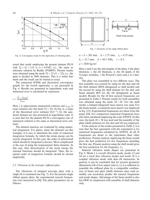
Fig. 7. Geometry <strong>of</strong> the single ribbed plate.<br />
Fig. 6. Convergence study <strong>for</strong> the eigenvalue <strong>of</strong> vibrating plate.<br />
noted that result employing the present element PL18<br />
with k4 2 ˆ k2 5 ˆ 5=6 is x ˆ 0:4342, i.e., the same as<br />
reference solution by Reddy (FOSDT). Present results<br />
were obtained using the mesh 32 32 (N ˆ 32), i.e., the<br />
plate is divided in 2048 elements. This is a rather ®ne<br />
mesh <strong>and</strong> the result can be treated as exact.<br />
The numerical (FEM) <strong>and</strong> theoretical convergence<br />
graphs <strong>for</strong> the fourth eigenvalue k 4 are presented in<br />
Fig. 6. Results are presented in logarithmic scale <strong>and</strong><br />
numerical error is calculated by expression<br />
e ˆ j^k k exact j<br />
k exact<br />
:<br />
Here ^k is approximate (numerical) solution <strong>and</strong> k exact is<br />
exact solution (<strong>for</strong> the mesh 32 32). In Fig. 6, a slope<br />
<strong>of</strong> the theoretical error estimate O…N 4 † <strong>for</strong> the quadratic<br />
element are also presented in logarithmic scale. It<br />
is seen that <strong>for</strong> the element PL18 a convergence rate <strong>of</strong><br />
numerical solution is the same as theoretical error estimate.<br />
The element matrices are evaluated by using numerical<br />
integration. For plates, when the elements are ¯at<br />
triangles, it is easy to determine the order <strong>of</strong> numerical<br />
integration <strong>for</strong>mula, by which the strain energy can be<br />
exactly integrated. In this case, the order <strong>of</strong> polynomial<br />
which should be integrated is known. More complicated<br />
is the case <strong>of</strong> using the isoparametric ®nite elements. In<br />
this case, after discretization <strong>of</strong> the strain energy the<br />
rational functions should be integrated. Thus, the required<br />
order <strong>of</strong> integration <strong>for</strong>mula should be chosen<br />
empirically.<br />
5.2. Vibration <strong>of</strong> the isotropic sti€ened plate<br />
The <strong>vibrations</strong> <strong>of</strong> clamped isotropic plate with a<br />
single rib is examined (see Fig. 7). For the present single<br />
ribbed square plate, the experimental natural frequencies<br />
were measured in [30]. The plate parameters are as<br />
follows:<br />
a ˆ b ˆ 203 mm; h ˆ 1:37 mm; t s ˆ 6:35 mm;<br />
h s ˆ 12:7 mm; E ˆ 68:7 GPa; m ˆ 0:3;<br />
q ˆ 2820 kg=m 3 :<br />
Here a <strong>and</strong> b are the side lengths <strong>of</strong> the plate, h the plate<br />
thickness, t s the rib thickness, h s the rib depth, E the<br />
Young's modulus, m the Poisson's ratio <strong>and</strong> q is a density.<br />
The plate was assembled in two di€erent ways. The<br />
®rst assembly was created by using <strong>for</strong> the skin <strong>and</strong> rib<br />
the shell element SH36 (designated as shell model) <strong>and</strong><br />
the second by using the shell element <strong>for</strong> the skin <strong>and</strong><br />
beam element B18 <strong>for</strong> the rib (designated as beam<br />
model). Results <strong>for</strong> the 24 ®rst natural frequencies are<br />
presented in Table 2. Present results <strong>for</strong> both assemblies<br />
was obtained using the mesh 24 24. For the shell<br />
model, a lumped (diagonal) mass matrix was used. For<br />
the beam model, a consistent mass matrix was employed<br />
in Eq. (22). Experimental frequencies are taken from the<br />
paper [30]. For comparison numerical frequencies have<br />
also been calculated employing the code ANSYS. In this<br />
case, the mesh 24 24 was used <strong>and</strong> the assembly <strong>of</strong> the<br />
plate (shell) elements <strong>for</strong> the skin <strong>and</strong> rib was employed.<br />
From analysis <strong>of</strong> the results presented in Table 2, it is<br />
seen that the best agreement with the experiment is <strong>for</strong><br />
numerical frequencies calculated by ANSYS. At all 18<br />
frequencies are closer to the experiment than other<br />
predictions. Present analysis employing the beam model<br />
gives the best prediction <strong>for</strong> ®ve frequencies including<br />
the ®rst one. Present analysis using the shell model gives<br />
the best prediction <strong>for</strong> the frequency f 10 .<br />
Selected vibration mode shapes are presented in<br />
Fig. 8. Mode 1 is overall vibration mode, modes 12 <strong>and</strong><br />
24 are a local skin vibration modes <strong>and</strong> mode 20 is a<br />
coupled vibration mode with skin±rib interaction. In<br />
general, it can be concluded that <strong>for</strong> present geometric<br />
dimensions (rib <strong>of</strong> low aspect ratio h s =t s ) it is sucient to<br />
assemble the sti€ened plate by a compatible combination<br />
<strong>of</strong> beam <strong>and</strong> plate (shell) elements since such assembly<br />
can accurately predict the natural frequencies<br />
<strong>and</strong> mode shapes. Advantage <strong>of</strong> the beam model is also<br />
less DOF in comparison with assembly <strong>of</strong> shell elements<br />
only.