Analysis for buckling and vibrations of composite ... - ResearchGate
Analysis for buckling and vibrations of composite ... - ResearchGate
Analysis for buckling and vibrations of composite ... - ResearchGate

Create successful ePaper yourself
Turn your PDF publications into a flip-book with our unique Google optimized e-Paper software.
368 R. Rikards et al. / Composite Structures 51 (2001) 361±370<br />
Table 4<br />
Natural frequencies [Hz] <strong>of</strong> laminated <strong>composite</strong> plate<br />
Mode Ref. [31] ANSYS Present<br />
With rib No rib With rib No rib With rib No rib<br />
1 213.8 85.1 213.1 85 215 85.6<br />
2 229.4 134 220.8 133.9 235.5 135.7<br />
3 270.2 207.4 270.3 206.3 274.5 208.1<br />
4 313.8 216.1 308.8 215.5 315.4 219.9<br />
5 354 252.5 353.5 251.4 361.4 256.3<br />
Exploring the mode shapes <strong>of</strong> the sti€ened plate it<br />
should be noted that, <strong>for</strong> example, <strong>for</strong> the ®rst frequency<br />
there is a coupled skin±rib antisymmetric vibration<br />
mode. This is due to low torsional sti€ness <strong>of</strong> the rib<br />
since the shear modulus G 23 <strong>of</strong> the <strong>composite</strong> is very low<br />
(see Table 3).<br />
5.4. Buckling <strong>of</strong> sti€ened isotropic plate under axial<br />
compression<br />
In order to verify the present element SH36 <strong>for</strong> solution<br />
<strong>of</strong> <strong>buckling</strong> problems a clamped sti€ened plate<br />
under axial compression is considered (see Fig. 9). The<br />
reference solution <strong>of</strong> the present numerical example was<br />
obtained in [32].<br />
The critical stress <strong>of</strong> the plate is given by<br />
<br />
r cr ˆ k<br />
<br />
; D ˆ<br />
p 2 D<br />
Eh 3<br />
a 2 h<br />
12…1 m 2 † : …24†<br />
Here critical parameter k is function <strong>of</strong> non-dimensional<br />
quantities.<br />
b ˆ b<br />
a ;<br />
j ˆ EI<br />
aD ;<br />
e ˆ A<br />
ah ;<br />
…25†<br />
where A is area, I the second moment <strong>of</strong> area <strong>of</strong> the<br />
sti€ener <strong>and</strong> h is a skin-plate thickness. The boundary<br />
conditions <strong>of</strong> the clamped plate are as follows:<br />
u; v; w; c x ; c y ; cj xˆ0;a; yˆ0 ˆ 0; u; w; c x ; c y ; cj yˆb ˆ 0:<br />
…26†<br />
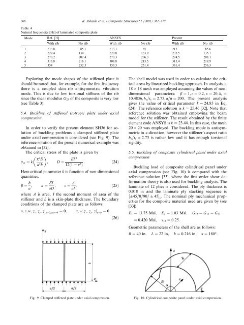
The shell model was used in order to calculate the critical<br />
stress by linearized <strong>buckling</strong> approach. In analysis, a<br />
18 18 mesh was employed assuming the values <strong>of</strong> nondimensional<br />
parameters: b ˆ 1; e ˆ 0:2; j ˆ 20; h s ˆ<br />
10:483h; h s =t s ˆ 2:75; a=h ˆ 200. The present analysis<br />
gives the value <strong>of</strong> critical parameter k ˆ 24:85 in Eq.<br />
(24). The reference solution is k ˆ 25:46 [32]. Note that<br />
reference solution was obtained employing the beam<br />
model <strong>for</strong> the sti€ener. The result obtained by the ®nite<br />
element code ANSYS is k ˆ 23:44. In this case, the mesh<br />
20 20 was employed. The <strong>buckling</strong> mode is antisymmetric<br />
in x-direction, however the sti€ener's aspect ratio<br />
h s =t s ˆ 2:75 is rather low <strong>and</strong> it has enough torsional<br />
rigidity.<br />
5.5. Buckling <strong>of</strong> <strong>composite</strong> cylindrical panel under axial<br />
compression<br />
Buckling load <strong>of</strong> <strong>composite</strong> cylindrical panel under<br />
axial compression (see Fig. 10) is compared with the<br />
reference solution [33], where the ®rst-order shear de<strong>for</strong>mation<br />
theory is also used <strong>for</strong> <strong>buckling</strong> analysis. The<br />
laminate <strong>of</strong> 12 plies is considered. The ply thickness is<br />
0.018 in <strong>and</strong> the laminate ply stacking sequence is<br />
‰45=0=90= 45Š s<br />
. The nominal ply mechanical properties<br />
<strong>for</strong> the <strong>composite</strong> material used are given by (see<br />
[33])<br />
E 1 ˆ 13:75 Msi; E 2 ˆ 1:03 Msi; G 12 ˆ G 13 ˆ G 23<br />
ˆ 0:420 Msi; m 12 ˆ 0:25:<br />
Geometric parameters <strong>of</strong> the shell are as follows:<br />
R ˆ 40 in; L ˆ 22 in; h ˆ 0:216 in; a ˆ 180°:<br />
Fig. 9. Clamped sti€ened plate under axial compression.<br />
Fig. 10. Cylindrical <strong>composite</strong> panel under axial compression.