Analysis for buckling and vibrations of composite ... - ResearchGate
Analysis for buckling and vibrations of composite ... - ResearchGate
Analysis for buckling and vibrations of composite ... - ResearchGate

Create successful ePaper yourself
Turn your PDF publications into a flip-book with our unique Google optimized e-Paper software.
R. Rikards et al. / Composite Structures 51 (2001) 361±370 365<br />
account. So, the beam displacement vector is the same as<br />
<strong>for</strong> shell Eq. (10) <strong>and</strong> the element displacement vector is<br />
given by<br />
v T e ˆ‰ve 1 ; ve 2 ; ve 3 Š;<br />
h<br />
veT i<br />
ˆ u i ; v i ; w i ; c i …1† ; ci …2† ; c i<br />
i<br />
: …21†<br />
At all <strong>for</strong> the present beam element there are 18 DOF<br />
<strong>and</strong> the element is designated as B18. Similar Timoshenko's<br />
beam ®nite element employing the third-order<br />
approximations was developed in [24].<br />
The ®nite elements SH36 <strong>and</strong> B18 can be used to<br />
assemble the sti€ened shells <strong>of</strong> an arbitrary shape since<br />
<strong>for</strong> both isoparametric elements the mapping technique<br />
is applied. The locking phenomenon <strong>for</strong> these elements<br />
can be avoided by using a selective integration technique<br />
[25].<br />
5. Numerical examples<br />
Further the vibration <strong>and</strong> <strong>buckling</strong> problems <strong>of</strong><br />
di€erent structures are analyzed. In order to evaluate<br />
the natural frequencies a linear eigenvalue problem is<br />
solved<br />
Ku kMu ˆ 0:<br />
…22†<br />
Here K <strong>and</strong> M is a global sti€ness <strong>and</strong> mass matrices, u<br />
is global displacement vector <strong>and</strong> k ˆ x 2 , where x ˆ<br />
2pf is a circular frequency <strong>and</strong> f is a frequency. The<br />
subspace iteration method [26], which is widely used <strong>for</strong><br />
large scale ®nite element calculations, is employed to<br />
solve Eq. (22).<br />
Di€erent methods are employed to estimate <strong>buckling</strong><br />
loads. The simplest is linearized <strong>buckling</strong> analysis, where<br />
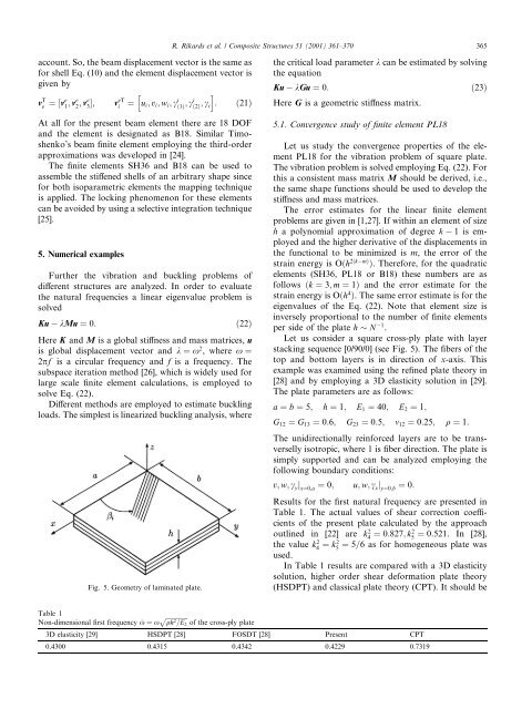
Fig. 5. Geometry <strong>of</strong> laminated plate.<br />
the critical load parameter k can be estimated by solving<br />
the equation<br />
Ku kGu ˆ 0:<br />
…23†<br />
Here G is a geometric sti€ness matrix.<br />
5.1. Convergence study <strong>of</strong> ®nite element PL18<br />
Let us study the convergence properties <strong>of</strong> the element<br />
PL18 <strong>for</strong> the vibration problem <strong>of</strong> square plate.<br />
The vibration problem is solved employing Eq. (22). For<br />
this a consistent mass matrix M should be derived, i.e.,<br />
the same shape functions should be used to develop the<br />
sti€ness <strong>and</strong> mass matrices.<br />
The error estimates <strong>for</strong> the linear ®nite element<br />
problems are given in [1,27]. If within an element <strong>of</strong> size<br />
h a polynomial approximation <strong>of</strong> degree k 1 is employed<br />
<strong>and</strong> the higher derivative <strong>of</strong> the displacements in<br />
the functional to be minimized is m, the error <strong>of</strong> the<br />
strain energy is O…h 2…km† †. There<strong>for</strong>e, <strong>for</strong> the quadratic<br />
elements (SH36, PL18 or B18) these numbers are as<br />
follows …k ˆ 3; m ˆ 1† <strong>and</strong> the error estimate <strong>for</strong> the<br />
strain energy is O…h 4 †. The same error estimate is <strong>for</strong> the<br />
eigenvalues <strong>of</strong> the Eq. (22). Note that element size is<br />
inversely proportional to the number <strong>of</strong> ®nite elements<br />
per side <strong>of</strong> the plate h N 1 .<br />
Let us consider a square cross-ply plate with layer<br />
stacking sequence [0/90/0] (see Fig. 5). The ®bers <strong>of</strong> the<br />
top <strong>and</strong> bottom layers is in direction <strong>of</strong> x-axis. This<br />
example was examined using the re®ned plate theory in<br />
[28] <strong>and</strong> by employing a 3D elasticity solution in [29].<br />
The plate parameters are as follows:<br />
a ˆ b ˆ 5; h ˆ 1; E 1 ˆ 40; E 2 ˆ 1;<br />
G 12 ˆ G 13 ˆ 0:6; G 23 ˆ 0:5; m 12 ˆ 0:25; q ˆ 1:<br />
The unidirectionally rein<strong>for</strong>ced layers are to be transverselly<br />
isotropic, where 1 is ®ber direction. The plate is<br />
simply supported <strong>and</strong> can be analyzed employing the<br />
following boundary conditions:<br />
v; w; c y j xˆ0;a ˆ 0; u; w; c x j yˆ0;b ˆ 0:<br />
Results <strong>for</strong> the ®rst natural frequency are presented in<br />
Table 1. The actual values <strong>of</strong> shear correction coecients<br />
<strong>of</strong> the present plate calculated by the approach<br />
outlined in [22] are k4 2 ˆ 0:827; k2 5 ˆ 0:521. In [28],<br />
the value k4 2 ˆ k2 5 ˆ 5=6 as <strong>for</strong> homogeneous plate was<br />
used.<br />
In Table 1 results are compared with a 3D elasticity<br />
solution, higher order shear de<strong>for</strong>mation plate theory<br />
(HSDPT) <strong>and</strong> classical plate theory (CPT). It should be<br />
Table 1<br />
p<br />
Non-dimensional ®rst frequency x ˆ x<br />
<br />
qh 2 =E 2 <strong>of</strong> the cross-ply plate<br />
3D elasticity [29] HSDPT [28] FOSDT [28] Present CPT<br />
0.4300 0.4315 0.4342 0.4229 0.7319