0-1 NOVA-LUKE Motherboard 1
0-1 NOVA-LUKE Motherboard 1
0-1 NOVA-LUKE Motherboard 1

Create successful ePaper yourself
Turn your PDF publications into a flip-book with our unique Google optimized e-Paper software.
<strong>NOVA</strong>-<strong>LUKE</strong> <strong>Motherboard</strong><br />
0-11
REVISION HISTORY<br />
Title<br />
<strong>NOVA</strong>-<strong>LUKE</strong> Intel Pentium M/Celeron M Motherbard<br />
Revision Number Description Date of Issue<br />
1.0 Initial release August 2006<br />
COPYRIGHT NOTICE<br />
The information in this document is subject to change without prior notice in order to<br />
improve reliability, design and function and does not represent a commitment on the part<br />
of the manufacturer.<br />
In no event is the manufacturer liable for direct, indirect, special, incidental, or<br />
consequential damages arising out of the use or inability to use the product or<br />
documentation, even if advised of the possibility of such damages.<br />
This document contains proprietary information protected by copyright. All rights are<br />
reserved. No part of this manual may be reproduced by any mechanical, electronic, or<br />
other means in any form without prior written permission of the manufacturer.<br />
TRADEMARKS<br />
IBM PC is a registered trademark of International Business Machines Corporation. INTEL<br />
is a registered trademark of INTEL Corporation. AMI is registered trademarks of American<br />
Megatrends Inc. Other product names mentioned herein are used for identification<br />
purposes only and may be trademarks and/or registered trademarks of their respective<br />
owners.<br />
2 IEI ® Technology, Corp.<br />
0-2
<strong>NOVA</strong>-<strong>LUKE</strong> <strong>Motherboard</strong><br />
Table of Contents<br />
1 INTRODUCTION................................................................................................... 15<br />
1.1 <strong>NOVA</strong>-<strong>LUKE</strong> OVERVIEW ....................................................................................... 16<br />
1.1.1 <strong>NOVA</strong>-<strong>LUKE</strong> Models ....................................................................................... 16<br />
1.1.2 Optional i<strong>LUKE</strong> Daughterboard ..................................................................... 16<br />
1.1.3 <strong>NOVA</strong>-<strong>LUKE</strong> Applications............................................................................... 16<br />
1.1.4 <strong>NOVA</strong>-<strong>LUKE</strong> Benefits...................................................................................... 16<br />
1.1.5 <strong>NOVA</strong>-<strong>LUKE</strong> Features..................................................................................... 17<br />
1.2 <strong>NOVA</strong>-<strong>LUKE</strong> OVERVIEW ....................................................................................... 18<br />
1.2.1 <strong>NOVA</strong>-<strong>LUKE</strong> Connectors ................................................................................ 19<br />
1.2.2 i<strong>LUKE</strong> Daughterboard Connectors ................................................................. 20<br />
1.3 TECHNICAL SPECIFICATIONS .................................................................................... 22<br />
1.3.1 <strong>NOVA</strong>-<strong>LUKE</strong> Specifications ............................................................................ 22<br />
1.3.2 Optional i<strong>LUKE</strong> Daughterboard Technical Specifications ............................. 23<br />
2 DETAILED SPECIFICATIONS ........................................................................... 25<br />
2.1 OVERVIEW ............................................................................................................... 26<br />
2.2 BOARD DIMENSIONS................................................................................................ 26<br />
2.3 CPU SUPPORT.......................................................................................................... 27<br />
2.4 SYSTEM CHIPSET ..................................................................................................... 28<br />
2.5 DATA FLOW.............................................................................................................. 29<br />
2.6 GRAPHICS SUPPORT ................................................................................................. 30<br />
2.7 OPTIONAL I<strong>LUKE</strong> LVDS DISPLAY SUPPORT ........................................................... 31<br />
2.8 MEMORY SUPPORT................................................................................................... 31<br />
2.9 PCI BUS INTERFACE SUPPORT ................................................................................. 31<br />
2.10 ETHERNET CONTROLLER ....................................................................................... 32<br />
2.10.1 Introduction.................................................................................................... 32<br />
2.10.2 Realtek RTL8110S Features........................................................................... 32<br />
2.11 DRIVE INTERFACES ................................................................................................ 33<br />
2.11.1 SATA Drives.................................................................................................... 33<br />
2.11.2 IDE HDD Interfaces....................................................................................... 33<br />
2.11.3 Compact Flash Support.................................................................................. 33<br />
2.12 SERIAL PORTS ........................................................................................................ 33<br />
0-33
2.13 REAL TIME CLOCK................................................................................................. 34<br />
2.14 SYSTEM MONITORING............................................................................................ 34<br />
2.15 INFRARED DATA ASSOCIATION (IRDA) INTERFACE................................................ 34<br />
2.16 USB INTERFACES................................................................................................... 34<br />
2.17 BIOS ..................................................................................................................... 34<br />
2.18 OPERATING TEMPERATURE AND TEMPERATURE CONTROL..................................... 35<br />
2.19 AUDIO CODEC........................................................................................................ 35<br />
2.20 POWER CONSUMPTION........................................................................................... 36<br />
2.21 PACKAGED CONTENTS AND OPTIONAL ACCESSORY ITEMS..................................... 37<br />
2.21.1 Package Contents........................................................................................... 37<br />
2.21.2 Optional Accessory Items............................................................................... 37<br />
3 CONNECTORS AND JUMPERS ......................................................................... 39<br />
3.1 PERIPHERAL INTERFACE CONNECTORS .................................................................... 40<br />
3.1.1 <strong>NOVA</strong>-<strong>LUKE</strong> Layout........................................................................................ 40<br />
3.1.2 Peripheral Interface Connectors ..................................................................... 41<br />
3.1.3 External Interface Panel Connectors............................................................... 43<br />
3.1.4 On-board Jumpers ........................................................................................... 44<br />
3.2 INTERNAL PERIPHERAL CONNECTORS...................................................................... 45<br />
3.2.1 +5VSB PS_ON................................................................................................. 45<br />
3.2.2 –12V Power Supply.......................................................................................... 46<br />
3.2.3 AT Power Connector........................................................................................ 46<br />
3.2.4 Audio Connector .............................................................................................. 47<br />
3.2.5 Compact Flash Connector ............................................................................... 48<br />
3.2.6 Fan Connector ................................................................................................. 50<br />
3.2.7 Front Panel Connector .................................................................................... 52<br />
3.2.8 GPIO Connector .............................................................................................. 53<br />
3.2.9 IDE Connector (Primary)................................................................................ 54<br />
3.2.10 IDE Connector (Secondary) .......................................................................... 56<br />
3.2.11 Inverter Power Connector.............................................................................. 58<br />
3.2.12 IR Interface Connector .................................................................................. 59<br />
3.2.13 LVDS Connector ............................................................................................ 60<br />
3.2.14 Keyboard/Mouse Connector .......................................................................... 61<br />
3.2.15 LCD LVDS Converter Module Connector 1 .................................................. 62<br />
3.2.16 LCD LVDS Converter Module Connector 2 .................................................. 64<br />
3.2.17 Parallel Port Connector ................................................................................ 65<br />
4 IEI ® Technology, Corp.<br />
0-4
<strong>NOVA</strong>-<strong>LUKE</strong> <strong>Motherboard</strong><br />
3.2.18 PC/104 Slot .................................................................................................... 66<br />
3.2.19 PCI-104 Slot................................................................................................... 70<br />
3.2.20 PCI Slot.......................................................................................................... 73<br />
3.2.21 Power Switch Connector................................................................................ 77<br />
3.2.22 Reset Button Connector ................................................................................. 78<br />
3.2.23 RS-232 Serial Port Connectors...................................................................... 79<br />
3.2.24 RS-232/422/485 Serial Port Connector......................................................... 80<br />
3.2.25 SATA Drive Connectors ................................................................................. 81<br />
3.2.26 TTL Connector ............................................................................................... 82<br />
3.2.27 Internal USB Connectors............................................................................... 83<br />
3.2.28 VGA Connector (Internal) ............................................................................. 84<br />
3.3 EXTERNAL INTERFACE CONNECTORS....................................................................... 85<br />
3.3.1 LAN Connectors............................................................................................... 86<br />
4 INSTALLATION AND CONFIGURATION ....................................................... 89<br />
4.1 ANTI-STATIC PRECAUTIONS...................................................................................... 90<br />
4.2 INSTALLATION CONSIDERATIONS ............................................................................. 90<br />
4.2.1 Installation Notices .......................................................................................... 90<br />
4.3 UNPACKING.............................................................................................................. 91<br />
4.3.1 Unpacking Precautions.................................................................................... 91<br />
4.3.2 Checklist........................................................................................................... 92<br />
4.4 <strong>NOVA</strong>-<strong>LUKE</strong> MOTHERBOARD INSTALLATION........................................................ 92<br />
4.4.1 Preinstalled Components ................................................................................. 93<br />
4.4.2 Components to Install ...................................................................................... 93<br />
4.4.3 DIMM Module Installation.............................................................................. 93<br />
4.4.3.1 Purchasing the Memory Module............................................................... 93<br />
4.4.3.2 DIMM Module Installation....................................................................... 94<br />
4.4.4 Optional i<strong>LUKE</strong> Daughterboard Installation.................................................. 95<br />
4.4.4.1 18-bit LVDS Connectivity ........................................................................ 95<br />
4.4.4.2 24-bit LVDS Connectivity ........................................................................ 96<br />
4.4.5 Peripheral Device Connection......................................................................... 97<br />
4.4.5.1 IDE Disk Drive Connector (IDE1) ........................................................... 98<br />
4.4.5.2 Compact Flash Connector......................................................................... 99<br />
4.4.5.3 Parallel Port Connector (LPT1) ................................................................ 99<br />
4.4.5.4 Audio Interface.......................................................................................... 99<br />
4.4.5.5 COM Port Connectors [COM1, COM2, COM3 and COM4]................. 100<br />
0-55
4.5 JUMPER SETTINGS.................................................................................................. 100<br />
4.5.1 Clear CMOS Jumper...................................................................................... 101<br />
4.5.2 CF Card Setup ............................................................................................... 102<br />
4.5.3 LCD Voltage Setup Jumper............................................................................ 103<br />
4.5.4 RS-232/485 Setup........................................................................................... 104<br />
4.5.5 RS-422/485 Jumper........................................................................................ 105<br />
4.5.6 COM2 Voltage Setup Jumper......................................................................... 106<br />
4.6 CHASSIS INSTALLATION ......................................................................................... 108<br />
4.7 REAR ETHERNET CONNECTORS.............................................................................. 108<br />
5 AMI BIOS SETUP................................................................................................ 109<br />
5.1 INTRODUCTION .......................................................................................................110<br />
5.1.1 Starting Setup..................................................................................................110<br />
5.1.2 Using Setup .....................................................................................................110<br />
5.1.3 Getting Help.................................................................................................... 111<br />
5.1.4 Unable to Reboot After Configuration Changes............................................. 111<br />
5.1.5 BIOS Menu Bar............................................................................................... 111<br />
5.2 MAIN ......................................................................................................................112<br />
5.3 ADVANCED..............................................................................................................113<br />
5.3.1 CPU Configuration.........................................................................................114<br />
5.3.2 IDE Configuration ..........................................................................................115<br />
5.3.2.1 IDE Master, IDE Slave ............................................................................117<br />
5.3.3 Super IO Configuration.................................................................................. 121<br />
5.3.4 Hardware Health Configuration.................................................................... 127<br />
5.3.5 ACPI Configuration ....................................................................................... 128<br />
5.3.5.1 Advanced ACPI Configuration ............................................................... 130<br />
5.3.6 APM Configuration........................................................................................ 132<br />
5.3.7 USB Configuration......................................................................................... 135<br />
5.4 PCI/PNP ................................................................................................................ 138<br />
5.5 BOOT ..................................................................................................................... 144<br />
5.5.1 Boot Settings Configuration........................................................................... 145<br />
5.5.2 Boot Device Priority ...................................................................................... 147<br />
5.5.3 Hard Disk Drives ........................................................................................... 149<br />
5.5.4 Removable Drives .......................................................................................... 150<br />
5.5.5 CD/DVD Drives............................................................................................. 152<br />
5.6 SECURITY............................................................................................................... 153<br />
6 IEI ® Technology, Corp.<br />
0-6
<strong>NOVA</strong>-<strong>LUKE</strong> <strong>Motherboard</strong><br />
5.7 CHIPSET ................................................................................................................. 155<br />
5.7.1 Northbridge VIA CN400 Configuration......................................................... 155<br />
5.7.1.1 DRAM Clock/Timing Configurations .................................................... 156<br />
5.7.1.2 AGP Features Configuration................................................................... 158<br />
5.7.1.3 V-Link Features Configuration ............................................................... 160<br />
5.7.2 SouthBridge Configuration............................................................................ 161<br />
5.8 EXIT....................................................................................................................... 164<br />
6 SOFTWARE DRIVERS ....................................................................................... 167<br />
6.1 AVAILABLE SOFTWARE DRIVERS ............................................................................ 168<br />
6.2 4-IN-1 DRIVER INSTALLATION................................................................................ 168<br />
6.3 REALTEK AUDIO DRIVER INSTALLATION ............................................................... 175<br />
6.4 LAN DRIVER INSTALLATION ................................................................................. 184<br />
A BIOS CONFIGURATION OPTIONS ................................................................ 193<br />
A.1 BIOS CONFIGURATION OPTIONS........................................................................... 194<br />
B WATCHDOG TIMER .......................................................................................... 197<br />
C ADDRESS MAPPING.......................................................................................... 201<br />
C.1 IO ADDRESS MAP ................................................................................................. 202<br />
C.2 1ST MB MEMORY ADDRESS MAP ......................................................................... 202<br />
C.3 IRQ MAPPING TABLE............................................................................................ 203<br />
C.4 DMA CHANNEL ASSIGNMENTS............................................................................. 203<br />
D EXTERNAL AC’97 AUDIO CODEC ................................................................. 205<br />
D.1 INTRODUCTION ..................................................................................................... 206<br />
D.1.1 Accessing the AC’97 CODEC....................................................................... 206<br />
D.1.2 Driver Installation......................................................................................... 206<br />
D.2 SOUND EFFECT CONFIGURATION........................................................................... 207<br />
D.2.1 Accessing the Sound Effects Manager .......................................................... 207<br />
D.2.2 Sound Effect Manager Configuration Options ............................................. 209<br />
E<br />
INDEX.....................................................................................................................211<br />
0-77
List of Figures<br />
Figure 1-1: <strong>NOVA</strong>-<strong>LUKE</strong> Overview ............................................................................18<br />
Figure 1-2: <strong>NOVA</strong>-<strong>LUKE</strong> Solder Side Overview .......................................................19<br />
Figure 1-3: I<strong>LUKE</strong> Daughterboard Overview (Front Side).......................................21<br />
Figure 2-1: <strong>NOVA</strong>-<strong>LUKE</strong> Dimension (mm) ................................................................26<br />
Figure 2-2: <strong>NOVA</strong> -<strong>LUKE</strong> External Interface Connector Dimensions (mm)...........27<br />
Figure 2-3: Data Flow Block Diagram........................................................................29<br />
Figure 3-1: Connector and Jumper Locations .........................................................40<br />
Figure 3-2: Connector and Jumper Locations (Solder Side)..................................41<br />
Figure 3-3: +5VSB PS_ON Connector Location.......................................................45<br />
Figure 3-4: -12V Power Supply Connector Location ...............................................46<br />
Figure 3-5: AT Power Connector Location ...............................................................47<br />
Figure 3-6: Audio Connector Location......................................................................48<br />
Figure 3-7: Compact Flash Connector Location......................................................49<br />
Figure 3-8: Fan Connector Location .........................................................................51<br />
Figure 3-9: Front Panel Connector Locations..........................................................52<br />
Figure 3-10: GPIO Connector Pinout Locations ......................................................53<br />
Figure 3-11: Primary IDE Device Connector Locations...........................................55<br />
Figure 3-12: Secondary IDE Device Connector Locations......................................57<br />
Figure 3-13: Inverter Connector Locations ..............................................................58<br />
Figure 3-14: IR Connector Pinout Locations............................................................59<br />
Figure 3-15: LVDS Connector Pinout Locations (on i<strong>LUKE</strong>) ..................................60<br />
Figure 3-16: Keyboard/Mouse Connector Location.................................................62<br />
Figure 3-17: LVDS Converter Module Connector 1 Locations ...............................63<br />
Figure 3-18: LVDS Converter Module Connector 2 Locations ...............................64<br />
Figure 3-19: Parallel Port Connector Location.........................................................65<br />
Figure 3-20: PC/104 Slot Location .............................................................................68<br />
Figure 3-21: PCI-104 Slot Location............................................................................71<br />
Figure 3-22: PCI Slot Location ...................................................................................74<br />
Figure 3-23: Power Switch Connector Locations ....................................................77<br />
8 IEI ® Technology, Corp.<br />
0-8
<strong>NOVA</strong>-<strong>LUKE</strong> <strong>Motherboard</strong><br />
Figure 3-24: Reset Button Connector Locations .....................................................78<br />
Figure 3-25: RS-232 Serial Port Connector Locations ............................................79<br />
Figure 3-26: RS-232/422/485 Serial Port Connector Location ................................80<br />
Figure 3-27: SATA Drive Connector Locations........................................................81<br />
Figure 3-28: TTL Connector Locations .....................................................................82<br />
Figure 3-29: USB Connector Pinout Locations........................................................84<br />
Figure 3-30: VGA Connector Location......................................................................85<br />
Figure 3-31: <strong>NOVA</strong>-<strong>LUKE</strong> Rear Panel........................................................................86<br />
Figure 3-32: RJ-45 Ethernet Connector ....................................................................87<br />
Figure 4-1: DIMM Module Installation........................................................................94<br />
Figure 4-2: 18-bit LVDS i<strong>LUKE</strong> Connectivity ............................................................96<br />
Figure 4-3: 24-bit LVDS i<strong>LUKE</strong> Connectivity ............................................................97<br />
Figure 4-4: Connection of IDE Connector ................................................................98<br />
Figure 4-5: Clear CMOS Jumper ............................................................................. 102<br />
Figure 4-6: CF Card Setup Jumper Pinout Locations .......................................... 103<br />
Figure 4-7: LCD Voltage Setup Jumper Pinout Locations................................... 104<br />
Figure 4-8: COM2 Setup Jumper Pinout Locations .............................................. 105<br />
Figure 4-9: RS-422/485 Jumper Pinout Locations ................................................ 106<br />
Figure 4-10: COM2 Voltage Setup Jumper Pinout Locations.............................. 107<br />
Figure 6-1: Access the <strong>NOVA</strong>-<strong>LUKE</strong> Drivers......................................................... 168<br />
Figure 6-2: Setup Utility Icon .................................................................................. 169<br />
Figure 6-3: 4 in 1 Icon .............................................................................................. 170<br />
Figure 6-4: VIA Chipset Driver Installation Welcome Screen .............................. 171<br />
Figure 6-5: Readme Information ............................................................................. 171<br />
Figure 6-6: VIA Chipset Driver Installation Type................................................... 172<br />
Figure 6-7: Driver Selection .................................................................................... 173<br />
Figure 6-8: VIA PCI IDE Bus Driver Selection ....................................................... 174<br />
Figure 6-9: Restart the Computer........................................................................... 175<br />
Figure 6-10: Access the <strong>NOVA</strong>-<strong>LUKE</strong> Drivers....................................................... 175<br />
Figure 6-11: Select Audio ........................................................................................ 176<br />
Figure 6-12: RealTek ................................................................................................ 177<br />
Figure 6-13: ALC655 Icon ........................................................................................ 178<br />
Figure 6-14: Audio Setup Icon ................................................................................ 179<br />
0-99
Figure 6-15: Audio Driver Install Shield Wizard Starting ..................................... 179<br />
Figure 6-16: Audio Driver Setup Preparation ........................................................ 180<br />
Figure 6-17: Audio Driver Welcome Screen .......................................................... 181<br />
Figure 6-18: Audio Driver Software Configuration ............................................... 181<br />
Figure 6-19: Audio Driver Digital Signal ................................................................ 182<br />
Figure 6-20: Audio Driver Installation Begins ....................................................... 183<br />
Figure 6-21: Audio Driver Installation Complete................................................... 184<br />
Figure 6-22: Access the <strong>NOVA</strong>-<strong>LUKE</strong> Drivers....................................................... 185<br />
Figure 6-23: LAN Driver Menu Option.................................................................... 185<br />
Figure 6-24: OS Icon ................................................................................................ 186<br />
Figure 6-25: RealTek Setup Icon............................................................................. 187<br />
Figure 6-26: LAN Setup Icon ................................................................................... 188<br />
Figure 6-27: LAN Welcome Screen......................................................................... 189<br />
Figure 6-28: Install LAN ........................................................................................... 190<br />
Figure 6-29: LAN Driver Installation....................................................................... 190<br />
Figure 6-30: Exit LAN Driver Setup ........................................................................ 191<br />
10 IEI ® Technology, Corp.<br />
0-10
<strong>NOVA</strong>-<strong>LUKE</strong> <strong>Motherboard</strong><br />
List of Tables<br />
Table 1-1: Technical Specifications ..........................................................................23<br />
Table 1-2: i<strong>LUKE</strong> Technical Specifications ..............................................................23<br />
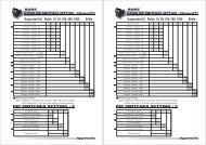
Table 2-1: Power Consumption 1 ..............................................................................36<br />
Table 2-2: Power Consumption 2 ..............................................................................37<br />
Table 3-1: Peripheral Interface Connectors..............................................................43<br />
Table 3-2: External Interface Connectors .................................................................43<br />
Table 3-3: On-board Jumpers ....................................................................................44<br />
Table 3-4: +5VSB PS_ON Connector Pinouts ..........................................................45<br />
Table 3-5: -12V Power Supply Connector Pinouts...................................................46<br />
Table 3-6: ATX Power Connector Pinouts ................................................................47<br />
Table 3-7: Audio Connector Pinouts.........................................................................48<br />
Table 3-8: Compact Flash Connector Pinouts .........................................................50<br />
Table 3-9: Fan Connector Pinouts.............................................................................51<br />
Table 3-10: Front Panel Connector Pinouts .............................................................53<br />
Table 3-11: GPIO Connector Pinouts ........................................................................54<br />
Table 3-12: Primary IDE Connector Pinouts.............................................................56<br />
Table 3-13: Secondary IDE Connector Pinouts........................................................58<br />
Table 3-14: Inverter Power Connector Pinouts ........................................................59<br />
Table 3-15: IR Connector Pinouts..............................................................................60<br />
Table 3-16: LVDS Connector Pinouts........................................................................61<br />
Table 3-17: Keyboard/Mouse Connector Pinouts ....................................................62<br />
Table 3-18: LVDS Converter Module Connector 1 Pinouts.....................................63<br />
Table 3-19: LVDS Converter Module Connector 2 Pinouts.....................................65<br />
Table 3-20: Parallel Port Connector Pinouts ............................................................66<br />
Table 3-21: PC/104 Slot Connector Pinouts .............................................................70<br />
Table 3-22: PCI-104 Slot Connector Pinouts ............................................................72<br />
Table 3-23: PCI Slot ....................................................................................................76<br />
Table 3-24: Power Switch Connector Pinouts..........................................................77<br />
Table 3-25: Reset Button Connector Pinouts...........................................................78<br />
0-11
Table 3-26: RS-232 Serial Port Connector Pinouts..................................................79<br />
Table 3-27: RS-232/RS-422/RS-485 Serial Port Connector Pinouts .......................80<br />
Table 3-28: SATA Drive Connector Pinouts .............................................................82<br />
Table 3-29: TTL Connector Pinouts...........................................................................83<br />
Table 3-30: USB Port Connector Pinouts .................................................................84<br />
Table 3-31: VGA Connector Pinouts .........................................................................85<br />
Table 3-32: LAN Pinouts.............................................................................................86<br />
Table 3-33: RJ-45 Ethernet Connector LEDs............................................................87<br />
Table 4-1: IEI Provided Cables...................................................................................98<br />
Table 4-2: Jumpers ................................................................................................. 100<br />
Table 4-3: Clear CMOS Jumper Settings ............................................................... 101<br />
Table 4-4: CF Card Setup Jumper Settings ........................................................... 102<br />
Table 4-5: LCD Voltage Setup Jumper Settings.................................................... 104<br />
Table 4-6: COM2 Setup Jumper Settings............................................................... 105<br />
Table 4-7: RS-422/485 Jumper Settings................................................................. 106<br />
Table 4-8: COM2 Voltage Setup Jumper Settings................................................. 107<br />
Table 5-1: BIOS Navigation Keys............................................................................ 111<br />
12 IEI ® Technology, Corp.<br />
0-12
<strong>NOVA</strong>-<strong>LUKE</strong> <strong>Motherboard</strong><br />
List of BIOS Menus<br />
BIOS Menu 1: Main ................................................................................................. 112<br />
BIOS Menu 2: Advanced.......................................................................................... 114<br />
BIOS Menu 3: CPU Configuration........................................................................... 115<br />
BIOS Menu 4: IDE Configuration ............................................................................ 116<br />
BIOS Menu 5: IDE Master and IDE Slave Configuration....................................... 118<br />
BIOS Menu 6: Super IO Configuration ................................................................... 122<br />
BIOS Menu 7: Hardware Health Configuration...................................................... 127<br />
Menu 8: ACPI Configuration ................................................................................... 129<br />
Menu 9: Advanced ACPI Configuration ................................................................. 131<br />
Menu 10:Advanced Power Management Configuration....................................... 133<br />
BIOS Menu 11: USB Configuration......................................................................... 136<br />
BIOS Menu 12: PCI/PnP Configuration .................................................................. 140<br />
BIOS Menu 13: Boot................................................................................................. 145<br />
BIOS Menu 14: Boot Settings Configuration......................................................... 146<br />
BIOS Menu 15: Boot Device Priority Settings ....................................................... 148<br />
BIOS Menu 16: Hard Disk Drives ............................................................................ 150<br />
BIOS Menu 17: Removable Drives.......................................................................... 151<br />
BIOS Menu 18: CD/DVD Drives ............................................................................... 153<br />
BIOS Menu 19: Security........................................................................................... 154<br />
BIOS Menu 20: Chipset............................................................................................ 155<br />
BIOS Menu 21:Northbridge Chipset Configuration .............................................. 156<br />
BIOS Menu 22: DRAM Clock/Timing Configuration.............................................. 157<br />
BIOS Menu 23: AGP Features Configuration ........................................................ 159<br />
BIOS Menu 24: V-Link Configuration ..................................................................... 160<br />
BIOS Menu 25:SouthBridge Chipset Configuration ............................................. 162<br />
BIOS Menu 26:Exit ................................................................................................. 164<br />
0-13
Glossary<br />
AC ’97 Audio Codec 97<br />
ACPI Advanced Configuration and<br />
Power Interface<br />
APM Advanced Power Management<br />
ARMD ATAPI Removable Media Device<br />
ASKIR Shift Keyed Infrared<br />
ATA Advanced Technology<br />
Attachments<br />
BIOS Basic Input/Output System<br />
CFII Compact Flash Type 2<br />
CMOS Complementary Metal Oxide<br />
Semiconductor<br />
CPU Central Processing Unit<br />
Codec Compressor/Decompressor<br />
COM Serial Port<br />
DAC Digital to Analog Converter<br />
DDR Double Data Rate<br />
DIMM Dual Inline Memory Module<br />
DIO Digital Input/Output<br />
DMA Direct Memory Access<br />
EIDE Enhanced IDE<br />
EIST Enhanced Intel SpeedStep<br />
Technology<br />
FDD Floppy Disk Drive<br />
FDC Floppy Disk Connector<br />
FFIO Flexible File Input/Output<br />
FIFO First In/First Out<br />
FSB Front Side Bus<br />
IrDA Infrared Data Association<br />
HDD<br />
IDE<br />
I/O<br />
Hard Disk Drive<br />
Integrated Data Electronics<br />
Input/Output<br />
ICH4 I/O Controller Hub 4<br />
L1 Cache Level 1 Cache<br />
L2 Cache Level 2 Cache<br />
LCD<br />
LPT<br />
LVDS<br />
MAC<br />
OS<br />
PCI<br />
PIO<br />
PnP<br />
POST<br />
RAM<br />
SATA<br />
Liquid Crystal Display<br />
Parallel Port Connector<br />
Low Voltage Differential Signaling<br />
Media Access Controller<br />
Operating System<br />
Peripheral Connect Interface<br />
Programmed Input Output<br />
Plug and Play<br />
Power On Self Test<br />
Random Access Memory<br />
Serial ATA<br />
S.M.A.R.T Self Monitoring Analysis and<br />
SPD<br />
S/PDI<br />
SDRAM<br />
SIR<br />
UART<br />
USB<br />
VGA<br />
Reporting Technology<br />
Serial Presence Detect<br />
Sony/Philips Digital Interface<br />
Synchronous Dynamic Random<br />
Access Memory<br />
Serial Infrared<br />
Universal Asynchronous<br />
Receiver-transmitter<br />
Universal Serial Bus<br />
Video Graphics Adapter<br />
14 IEI ® Technology, Corp.<br />
0-14
<strong>NOVA</strong>-<strong>LUKE</strong><br />
Chapter<br />
1<br />
1 Introduction<br />
Page 15
<strong>NOVA</strong>-<strong>LUKE</strong><br />
1.1 <strong>NOVA</strong>-<strong>LUKE</strong> Overview<br />
The 5.25” <strong>NOVA</strong>-<strong>LUKE</strong> VIA <strong>LUKE</strong> single board computer (SBC) is fully equipped with<br />
advanced multi-mode I/Os. The <strong>NOVA</strong>-<strong>LUKE</strong> is designed for system manufacturers,<br />
integrators, and VARs that want performance, reliability, and quality at a reasonable price.<br />
1.1.1 <strong>NOVA</strong>-<strong>LUKE</strong> Models<br />
The <strong>NOVA</strong>-<strong>LUKE</strong> series has two models:<br />
• <strong>NOVA</strong>-<strong>LUKE</strong>-1G-R10: 1GHz VIA <strong>LUKE</strong> CPU<br />
• <strong>NOVA</strong>-<strong>LUKE</strong>-533-R10: 533MHz VIA <strong>LUKE</strong> CPU<br />
1.1.2 Optional i<strong>LUKE</strong> Daughterboard<br />
The optional i<strong>LUKE</strong> daughterboard enables 18-bit or 24-bit LVDS connectivity.<br />
1.1.3 <strong>NOVA</strong>-<strong>LUKE</strong> Applications<br />
The <strong>NOVA</strong>-<strong>LUKE</strong> is designed for applications in the following areas:<br />
• Entertainment System:<br />
o Set-top-Box (STB)<br />
o Media Center<br />
o Home Theater<br />
• Mission critical industrial platform:<br />
o Multi-Media / Dual Screen POS<br />
o Interactive KIOSK / Photo Kiosk<br />
o HMI / Panel PC<br />
o Automation & Security system.<br />
• Mobile platform:<br />
o Car PC<br />
o Mobile/Portable Entertainment Device<br />
o Thin Client<br />
1.1.4 <strong>NOVA</strong>-<strong>LUKE</strong> Benefits<br />
Some of the <strong>NOVA</strong>-<strong>LUKE</strong> benefits include:<br />
Page 16<br />
IEI ® Technology, Corp.
<strong>NOVA</strong>-<strong>LUKE</strong><br />
• Flexible expansion capabilities:<br />
o PC/104-Plus<br />
o LVDS expansion daughter board<br />
o Dual 150MB/s SATA drive connectors<br />
• Maximum graphics capabilities:<br />
o LVDS/CRT dual screen<br />
o 2D&3D integrated MPEG decoder<br />
o Wide screen display support<br />
o Multi-media capability<br />
• Compact all in one solution providing:<br />
o Small Footprint design approach<br />
o Sufficient I/O support<br />
o Dual Screen support<br />
o Low heat generation<br />
o Fanless design<br />
1.1.5 <strong>NOVA</strong>-<strong>LUKE</strong> Features<br />
Some of the <strong>NOVA</strong>-<strong>LUKE</strong> features are listed below:<br />
• 5.25” form factor<br />
• RoHS compliant<br />
• Embedded 1GHz or 533MHz VIA <strong>LUKE</strong> processor<br />
• Dual-independent display functionality<br />
• Up to 1GB of 400MHz or 333MHz of DDR memory<br />
• Two high performance gigabit Ethernet (GbE) controllers onboard<br />
• Two SATA channels with transfer rates up to 150MB/s onboard<br />
• Eight USB 2.0 devices onboard<br />
• Integrated audio<br />
Page 17
<strong>NOVA</strong>-<strong>LUKE</strong><br />
1.2 <strong>NOVA</strong>-<strong>LUKE</strong> Overview<br />
Figure 1-1: <strong>NOVA</strong>-<strong>LUKE</strong> Overview<br />
Page 18<br />
IEI ® Technology, Corp.
<strong>NOVA</strong>-<strong>LUKE</strong><br />
Figure 1-2: <strong>NOVA</strong>-<strong>LUKE</strong> Solder Side Overview<br />
1.2.1 <strong>NOVA</strong>-<strong>LUKE</strong> Connectors<br />
The <strong>NOVA</strong>-<strong>LUKE</strong> has the following connectors onboard:<br />
• 1 x ATX power connector<br />
• 1 x AT power connector<br />
• 1 x Audio connector<br />
• 1 x CompactFlash (CF) connector (solder side)<br />
• 1 x Fan connector<br />
• 1 x Front panel connector<br />
• 1 x General purpose input/output (GPIO) connector<br />
Page 19
<strong>NOVA</strong>-<strong>LUKE</strong><br />
• 2 x IDE Interface connectors (40-pin and 44-pin)<br />
• 1 x Inverter power connector<br />
• 1 x IR interface connector<br />
• 1 x Keyboard/mouse connector<br />
• 2 x LCD LVDS converter module connectors (connect to the daughterboard)<br />
• 1 x PC/104-Plus connector (PCI interface)<br />
• 2 x PC/104 connectors (ISA interface)<br />
• 1 x PCI slot<br />
• 1 x Parallel port connector<br />
• 1 x Power switch connector<br />
• 1 x Reset switch connector<br />
• 1 x RS-232/485 serial port connector<br />
• 5 x RS-232 serial port connectors<br />
• 2 x SATA connectors<br />
• 4 x USB connectors<br />
• 1 x VGA connector<br />
The <strong>NOVA</strong>-<strong>LUKE</strong> has the following connectors on the board rear panel:<br />
• 2 x Ethernet connectors<br />
The <strong>NOVA</strong>-<strong>LUKE</strong> has the following onboard jumpers:<br />
• Clear CMOS<br />
• CF card setup<br />
• LCD voltage setup<br />
• RS-232/485 COM2 setup<br />
• RS-422/485 COM2 setup<br />
• COM2 voltage setup<br />
1.2.2 i<strong>LUKE</strong> Daughterboard Connectors<br />
Figure 1-3 shows the connectors on the front side of the i<strong>LUKE</strong> expansion daughterboard.<br />
Page 20<br />
IEI ® Technology, Corp.
<strong>NOVA</strong>-<strong>LUKE</strong><br />
Figure 1-3: I<strong>LUKE</strong> Daughterboard Overview (Front Side)<br />
The i<strong>LUKE</strong> has the following connectors onboard and accessible on the front side of the<br />
<strong>NOVA</strong>-<strong>LUKE</strong> (see Figure 1-3):<br />
• 1 x LVDS connector<br />
The i<strong>LUKE</strong> has one jumper (JP1) accessible on the front side (see Figure 1-3). The<br />
jumper is used to set single or dual channels for the LVDS display.<br />
Page 21
<strong>NOVA</strong>-<strong>LUKE</strong><br />
1.3 Technical Specifications<br />
1.3.1 <strong>NOVA</strong>-<strong>LUKE</strong> Specifications<br />
<strong>NOVA</strong>-<strong>LUKE</strong> technical specifications are listed in Table 1-1. Detailed descriptions of each<br />
specification can be found in Chapter 2 Detailed Specifications.<br />
Specification<br />
Form Factor<br />
CPU<br />
System Chipset<br />
Display<br />
Memory<br />
BIOS<br />
SSD<br />
Super I/O<br />
Audio<br />
LAN<br />
COM<br />
USB2.0<br />
IDE<br />
Parallel Port<br />
<strong>NOVA</strong>-<strong>LUKE</strong><br />
5.25” form factor<br />
Embedded 1GHz VIA <strong>LUKE</strong><br />
Embedded 533MHz VIA <strong>LUKE</strong><br />
VIA VT8237R+<br />
CRT integrated in VIA <strong>LUKE</strong><br />
Supports one 400MHz or 333MHz 184-pin DDR DIMM<br />
module with a maximum capacity of 1GB<br />
AMI BIOS Label<br />
Compact Flash (CF)<br />
W83697HG<br />
AC'97 Codec Realtek ALC655<br />
Dual RTL8110S<br />
Five RS-232C<br />
One RS-232/422/485<br />
Four USB 1.1 or 2.0 onboard connectors support two devices<br />
each<br />
One 40-pin and one 44-pin IDE each connects to two Ultra<br />
ATA33/66/100/133 IDE devices<br />
One LPT port connector<br />
Page 22<br />
IEI ® Technology, Corp.
<strong>NOVA</strong>-<strong>LUKE</strong><br />
SATA<br />
KB/MS<br />
WDT<br />
IrDA<br />
Digital I/O<br />
Fan connector<br />
Expansion<br />
Power<br />
Two SATA connectors with transfer rates up to 150MB/sec<br />
One PS/2 connector<br />
Software programmable 1-255 sec. by supper I/O<br />
SIR / ASKIR<br />
8-bit digital IO (4 input / 4 output) by super I/O<br />
One CPU Fan<br />
One PC/104-Plus interface<br />
One PCI slot<br />
+5V or +12V AT or ATX support<br />
Temperature 0ºC - 60ºC<br />
Humidity<br />
Dimensions<br />
Weight (GW/NW)<br />
5%~95% non-condensing<br />
146.05mm x 203.2mm<br />
1100g/500g<br />
Table 1-1: Technical Specifications<br />
1.3.2 Optional i<strong>LUKE</strong> Daughterboard Technical Specifications<br />
i<strong>LUKE</strong> technical specifications are listed in Table 1-2. Detailed descriptions of each<br />
specification can be found in Chapter 2 Detailed Specifications.<br />
Specification<br />
Chipset<br />
Display Connector<br />
POM-121IB<br />
VIA VT1631L<br />
LVDS<br />
Table 1-2: i<strong>LUKE</strong> Technical Specifications<br />
Page 23
<strong>NOVA</strong>-<strong>LUKE</strong><br />
THIS PAGE IS INTENTIONALLY LEFT BLANK<br />
Page 24<br />
IEI ® Technology, Corp.
<strong>NOVA</strong>-<strong>LUKE</strong><br />
Chapter<br />
2<br />
2 Detailed Specifications<br />
Page 25
<strong>NOVA</strong>-<strong>LUKE</strong><br />
2.1 Overview<br />
This chapter describes the specifications and onboard features of the <strong>NOVA</strong>-<strong>LUKE</strong> in<br />
detail.<br />
2.2 Board Dimensions<br />
The dimensions of the board are listed below and shown in Figure 2-1:<br />
• Length: 203.2mm<br />
• Width: 146.05mm<br />
Figure 2-1: <strong>NOVA</strong>-<strong>LUKE</strong> Dimension (mm)<br />
Page 26<br />
IEI ® Technology, Corp.
<strong>NOVA</strong>-<strong>LUKE</strong><br />
The external interface connector panel dimensions are shown in Figure 2-2.<br />
Figure 2-2: <strong>NOVA</strong> -<strong>LUKE</strong> External Interface Connector Dimensions (mm)<br />
2.3 CPU Support<br />
The <strong>NOVA</strong>-<strong>LUKE</strong> motherboard comes with a preinstalled 1GHz or 533MHz, ultra low<br />
voltage (ULV) VIA® Luke processor. The new VIA 'Luke' CoreFusion Processing Platform<br />
integrates the latest generation VIA Eden-N processor with the VIA CN400 Northbridge<br />
in a single, low power package.<br />
The Luke CoreFusion processor features include the following:<br />
• Rich Integration:- Highly integrated processing and digital media corelogic<br />
combination delivers leading performance in a single, power-efficient,<br />
space-saving package<br />
• S3 Graphics Unichrome Pro Graphics Core:- With an internal data flow<br />
equivalent to what is available to the latest AGP 8X graphics cards,<br />
Unichrome Pro has separate 128-bit data path between the Northbridge for<br />
pixel data flow and texture/command access. Separate 128-bit 2D and 3D<br />
graphics engines ensure optimal performance for all multimedia,<br />
entertainment, and productivity applications.<br />
• Flawless Digital Media Playback:- Unichrome Pro includes native support<br />
for the most popular digital video and audio playback through hardware<br />
MPEG-2/-4 acceleration and acclaimed VIA Vinyl Audio suite, delivering<br />
spectacular playback for entertainment devices.<br />
• Maximum Display Flexibility:- Unichrome Pro with its optimized shared<br />
memory architecture and high definition video support through the<br />
Page 27
<strong>NOVA</strong>-<strong>LUKE</strong><br />
Chromotion CE Video Display Engine, offers a breathtaking visual experience<br />
for the latest HDTV format displays. Support for LVDS and DVI interfaces<br />
enables complete flexibility for integration into a wide range of embedded and<br />
personal electronics applications<br />
• Native Serial ATA:- The VIA DriveStaion Controller Suite with native dual<br />
channel Serial ATA controller provides direct support for two 150MB/s Serial<br />
ATA devices and the SATAlite interface expands support for two additional<br />
SATA devices.<br />
2.4 System Chipset<br />
The <strong>NOVA</strong>-<strong>LUKE</strong> motherboard has a VIA VT8237R Plus Southbridge onboard. A<br />
summary of the available Southbridge features is listed below. For more information on<br />
this chipset please visit the VIA website.<br />
• VIA DriveStation Controller Suite<br />
o Serial ATA<br />
• Full duplex high performance 150MB/s Dual Channel Serial ATA interface<br />
• Support for additional two Serial ATA devices through SATALite interface<br />
o Parallel ATA 133<br />
• Supports up to four PATA devices<br />
• VIA Advanced Connectivity Suite<br />
o USB 2.0 Controller<br />
o Support for 8 USB 2.0/1.1 ports<br />
• Network Controller<br />
o Enterprise Class 10/100Mbps Fast Ethernet MAC<br />
• PCI & LPC bus controllers<br />
• VIA Vinyl Audio<br />
o VIA Vinyl integrated 5.1 surround sound<br />
• AC ’97 audio<br />
• VIA Six-TRAC codec<br />
o VIA Vinyl Gold onboard 7.1 surround sound<br />
• 24/96 resolution audio<br />
• VIA Envy24PT + VIA Six-TRAC Codec + additional DAC<br />
o VIA Stylus Audio drivers<br />
• Integrated Sensaura technology<br />
Page 28<br />
IEI ® Technology, Corp.
<strong>NOVA</strong>-<strong>LUKE</strong><br />
• Full 3D gaming support<br />
• V-MAP Architecture<br />
o Ultra V-Link<br />
• High throughput 1GB/s South Bridge/North Bridge interconnect<br />
• Supports new generation VIA North Bridges across all processor platforms<br />
o 8X V-Link<br />
• High speed 533MB/s South Bridge/North Bridge interconnect<br />
• Supports current generation VIA North Bridges across all processor platforms<br />
o VIA Hyperion 4in1 Unified Drivers<br />
• Optimized system performance and stability<br />
2.5 Data Flow<br />
Figure 2-3 shows the data flow between the two onboard chipsets and other components<br />
installed on the motherboard and described in the following sections of this chapter.<br />
Figure 2-3: Data Flow Block Diagram<br />
Page 29
<strong>NOVA</strong>-<strong>LUKE</strong><br />
2.6 Graphics Support<br />
The <strong>LUKE</strong> processor comes with a S3 Chromotion graphics engine. The features listed<br />
below are compatible with S3 Graphics' Chrome S20 Series processors:<br />
• Chromotion Video Acceleration:-<br />
o WMV9 Motion Compensation H/W Acceleration – Reduces CPU<br />
utilization when decoding Windows Media Video 9 (WMV9) files.<br />
o MPEG-2 IDCT and Motion Compensation H/W Acceleration –<br />
Reduces CPU utilization when decoding MPEG2 files.<br />
• Chromotion Hi-Def Support:-<br />
o HDTV Formats – Supports all 18 DTV ATSC formats.<br />
o Adaptive Per-Pixel De-Interlacing – Produces superior image quality for<br />
both still and motion images using a high quality De-Interlacing process.<br />
o Video Deblocking – Removes blocking artifacts inherent in low bit rate<br />
images.<br />
o ChromoVision – Displays full screen video on secondary HDTV display<br />
while a windows display of the video is on the primary CRT or DVI display.<br />
o ChromoVision Modes with ChromeView Non-Linear Scaling – Scales<br />
a standard 4:3 image to fill a wide-screen 16:9 display with excellent<br />
image quality.<br />
o PanelDrive – Eliminates blurring effects with motion video on panel<br />
displays by increasing panel response time.<br />
o ChromoColor – Provides adjustment controls for the brightness, contrast,<br />
hue and saturation of the display of video.<br />
• Chromotion Video Image Controls:-<br />
o ChromoColor Tonal Adjustment – Allows fine-tuning of luma values for<br />
the video display with controls for black point and white point<br />
enhancement.<br />
o ArtisticLicense Effects – Allows high quality image enhancements;<br />
including Sharpening, Soft Focus, Embossing, and Neon Edge effects.<br />
Page 30<br />
IEI ® Technology, Corp.
<strong>NOVA</strong>-<strong>LUKE</strong><br />
2.7 Optional i<strong>LUKE</strong> LVDS Display Support<br />
The <strong>NOVA</strong>-<strong>LUKE</strong> <strong>Motherboard</strong> supports LVDS displays. Using the i<strong>LUKE</strong> daughterboard<br />
enables connectivity to 18-bit or 24-bit flat panel displays. The i<strong>LUKE</strong> comes with an<br />
onboard VIA VT1631L Low Voltage Differential Signaling (LVDS) Transmitter. The VIA<br />
VT1631L is designed to support pixel data transmissions from a Host to a Flat Panel<br />
display ranging from VGA to UXGA resolutions. VIA VT1631 features are listed below.<br />
2.8 Memory Support<br />
• Complies with Open LDI Specification for Digital Display Interfaces<br />
• 25 to 85 MHz Input Clock Support<br />
• Supports VGA through UXGA Panel Resolution<br />
• Power-down mode
<strong>NOVA</strong>-<strong>LUKE</strong><br />
• 33MHz Revision 2.2 is implemented<br />
• Maximum throughput: 133MB/sec<br />
• One PCI REQ/GNT pair can be given higher arbitration priority (intended for<br />
external 1394 host controller)<br />
• 64-bit addressing supported<br />
2.10 Ethernet Controller<br />
2.10.1 Introduction<br />
The Realtek RTL8110S Ethernet controller combines a triple-speed IEEE 802.3 compliant<br />
Media Access Controller (MAC) with a triple-speed Ethernet transceiver, 32-bit PCI bus<br />
controller, and embedded memory. The device supports the PCI v2.2 bus interface for<br />
host communications with power management, and is compliant with the IEEE 802.3<br />
specification for 10/100Mbps Ethernet and the IEEE 802.3ab specification for 1000Mbps<br />
Ethernet. It also supports an auxiliary power auto-detect function, and will auto-configure<br />
related bits of the PCI power management registers in PCI configuration space.<br />
2.10.2 Realtek RTL8110S Features<br />
Realtek RTL8110S features are listed below<br />
• Integrated 10/100/1000 transceiver<br />
• Auto-Negotiation with Next page capability<br />
• Supports PCI 2.2, 32bit, 33/66MHz<br />
• Supports pair swap/polarity/skew correction<br />
• Crossover Detection & Auto-Correction<br />
• Wake-on-LAN and remote wake-up support<br />
• Microsoft® NDIS5 Checksum Offload (IP, TCP, UDP) and largesend offload<br />
support<br />
• Supports Full Duplex flow control (IEEE 802.3x)<br />
• Fully compliant with IEEE 802.3, IEEE 802.3u, IEEE 802.3ab<br />
• Supports IEEE 802.1Q VLAN tagging<br />
• Serial EEPROM<br />
• 3.3V signaling, 5V PCI I/O tolerant<br />
• Transmit/Receive FIFO (8K/64K) support<br />
• Supports power down/link down power saving<br />
Page 32<br />
IEI ® Technology, Corp.
<strong>NOVA</strong>-<strong>LUKE</strong><br />
• JTAG support<br />
• Supports PCI Clock Run Pin<br />
• 128-pin QFP<br />
•<br />
2.11 Drive Interfaces<br />
The <strong>NOVA</strong>-<strong>LUKE</strong> can support the following drive interfaces.<br />
• 2 x SATA drives<br />
• 2 x IDE devices<br />
• 1 x CF Type 2 card<br />
2.11.1 SATA Drives<br />
The <strong>NOVA</strong>-<strong>LUKE</strong> supports two, first generation SATA drives with transfer rates of up to<br />
150MB/s<br />
2.11.2 IDE HDD Interfaces<br />
The <strong>NOVA</strong>-<strong>LUKE</strong> southbridge chipset IDE controller supports up to four HDDs with the<br />
following specifications:<br />
• Supports PIO IDE transfers up to 16MB/s<br />
• Supports Ultra ATA/133 devices with data transfer rates up to 133MB/s<br />
2.11.3 Compact Flash Support<br />
A standard 3.3mm thick CF Type I or 5mm thick CF Type II card can be inserted into the<br />
CompactFlash ® slot on the <strong>NOVA</strong>-<strong>LUKE</strong> PCB. CompactFlash ® cards with data rates up to<br />
66MB/sec and capacities up to 137GB are supported.<br />
2.12 Serial Ports<br />
The <strong>NOVA</strong>-<strong>LUKE</strong> has six high-speed UART serial ports, configured as COM1, COM2,<br />
COM3, COM4, COM5 and COM6. The serial ports have the following specifications.<br />
• 16C550 UART with 16-byte FIFO buffer<br />
• 115.2Kbps transmission rate<br />
Page 33
<strong>NOVA</strong>-<strong>LUKE</strong><br />
COM2 can be configured as RS-232, RS-424 or RS-485. COM2 can also be configured as<br />
an infrared interface.<br />
2.13 Real Time Clock<br />
256-byte battery backed CMOS RAM<br />
2.14 System Monitoring<br />
The <strong>NOVA</strong>-<strong>LUKE</strong> is capable of self-monitoring various aspects of its operating status<br />
including:<br />
• CPU, chipset, and battery voltage, +3.3V, +5V, and +12V<br />
• RPM of cooling fans<br />
• CPU and board temperatures (by the corresponding embedded sensors)<br />
2.15 Infrared Data Association (IrDA) Interface<br />
The <strong>NOVA</strong>-<strong>LUKE</strong> IrDA supports the following interfaces.<br />
• Serial Infrared (SIR)<br />
• Shift Keyed Infrared (ASKIR)<br />
If an IrDA port is need, COM2 must be configured as either SIR or ASKIR mode in the<br />
BIOS under Super IO devices. Normal RS-232 COM 2 is then disabled.<br />
2.16 USB Interfaces<br />
2.17 BIOS<br />
The <strong>NOVA</strong>-<strong>LUKE</strong> supports eight USB 2.0 or USB 1.1 devices. Two are connected<br />
externally and the remaining six internally.<br />
The <strong>NOVA</strong>-<strong>LUKE</strong> uses a licensed copy of AMI BIOS. The features of the flash BIOS used<br />
are listed below:<br />
• SMIBIOS (DMI) compliant<br />
• Console redirection function support<br />
• PXE (Pre-Boot Execution Environment) support<br />
Page 34<br />
IEI ® Technology, Corp.
<strong>NOVA</strong>-<strong>LUKE</strong><br />
• USB booting support<br />
2.18 Operating Temperature and Temperature Control<br />
The maximum and minimum operating temperatures for the <strong>NOVA</strong>-<strong>LUKE</strong> are listed below.<br />
• Minimum Operating Temperature: 0ºC (32°F)<br />
• Maximum Operating Temperature: 60°C (140°F)<br />
A heat sink must always be installed on the CPU when the system is run. A cooling fan<br />
may or may not be required depending on the CPU being used.<br />
2.19 Audio Codec<br />
The <strong>NOVA</strong>-<strong>LUKE</strong> has an integrated REALTEK ALC655 CODEC. The ALC655 CODEC is<br />
a 16-bit, full-duplex AC'97 Rev. 2.3 compatible six-channel audio CODEC designed for PC<br />
multimedia systems, including host/soft audio and AMR/CNR-based designs. Some of the<br />
features of the codec are listed below.<br />
• Meets performance requirements for audio on PC99/2001 systems<br />
• Meets Microsoft WHQL/WLP 2.0 audio requirements<br />
• 16-bit Stereo full-duplex CODEC with 48KHz sampling rate<br />
• Compliant with AC'97 Rev 2.3 specifications<br />
• Front-Out, Surround-Out, MIC-In and LINE-In Jack Sensing<br />
• 14.318MHz -> 24.576MHz PLL to eliminate crystal<br />
• 12.288MHz BITCLK input<br />
• Integrated PCBEEP generator to save buzzer<br />
• Interrupt capability<br />
• Three analog line-level stereo inputs with 5-bit volume control, LINE_IN, CD,<br />
AUX<br />
• High-quality differential CD input<br />
• Two analog line-level mono inputs: PCBEEP, PHONE-IN<br />
• Two software selectable MIC inputs<br />
• Dedicated Front-MIC input for front panel applications (software selectable)<br />
• Boost preamplifier for MIC input<br />
• LINE input shared with surround output; MIC input shared with Center and<br />
LFE output<br />
Page 35
<strong>NOVA</strong>-<strong>LUKE</strong><br />
• Built-in 50mW/20ohm amplifier for both Front-out and Surround-Out<br />
• External Amplifier Power Down (EAPD) capability<br />
• Power management and enhanced power saving features<br />
• Supports Power-Off CD function<br />
• Adjustable VREFOUT control<br />
• Supports 48KHz S/PDIF output, complying with AC'97 Rev 2.3 specifications<br />
• Supports 32K/44.1K/48KHz S/PDIF input<br />
• Power support: Digital: 3.3V; Analog: 3.3V/5V<br />
• Standard 48-pin LQFP package<br />
• EAX 1.0 & 2.0 compatible<br />
• Direct Sound 3D compatible<br />
• A3D compatible<br />
• I3DL2 compatible<br />
• HRTF 3D positional audio<br />
• 10-band software equalizer<br />
• Voice cancellation and key shifting in Karaoke mode<br />
• AVRack® Media Player<br />
• Configuration Panel for improved user convenience<br />
2.20 Power Consumption<br />
Table 2-1 shows the power consumption parameters for the <strong>NOVA</strong>-<strong>LUKE</strong>-1G-R10 when a<br />
1GHz VIA <strong>LUKE</strong> processor is mounted on the board and 1GB of 400MHz DDR SDRAM is<br />
used.<br />
Voltage<br />
Current<br />
+5V 4.74A<br />
+12V 0.02A<br />
+5VSB 0.07A<br />
Table 2-1: Power Consumption 1<br />
Table 2-2 shows the power consumption parameters for the <strong>NOVA</strong>-<strong>LUKE</strong>-533-R10 when<br />
a 533MHz VIA <strong>LUKE</strong> processor is mounted on the board and 1GB of 400MHz DDR<br />
SDRAM is used.<br />
Page 36<br />
IEI ® Technology, Corp.
<strong>NOVA</strong>-<strong>LUKE</strong><br />
Voltage<br />
Current<br />
+5V 3.89A<br />
+12V 0.02A<br />
+5VSB 0.07A<br />
Table 2-2: Power Consumption 2<br />
2.21 Packaged Contents and Optional Accessory Items<br />
2.21.1 Package Contents<br />
The <strong>NOVA</strong>-<strong>LUKE</strong> is shipped with the following components.<br />
• 1x <strong>NOVA</strong>-<strong>LUKE</strong> single board computer<br />
• 1 x ATA 66/100 flat cable<br />
• 2 x SATA cables<br />
• 1 x SATA power cable<br />
• 3 x Single RS-232 cables<br />
• 1 x RS-232/422/485 cable<br />
• 1 x KB/MS cable<br />
• 1 x VGA cable<br />
• 1 x USB cable<br />
• 1 x Audio cable<br />
• 1 x Mini jumper pack<br />
• 1x Utility CD<br />
• 1x Quick Installation Guide<br />
2.21.2 Optional Accessory Items<br />
The items shown in the list below are optional accessory items are purchased separately.<br />
• LVDS function daughterboard<br />
• ATX power cable<br />
• LPT cable<br />
Page 37
<strong>NOVA</strong>-<strong>LUKE</strong><br />
THIS PAGE IS INTENTIONALLY LEFT BLANK<br />
Page 38<br />
IEI ® Technology, Corp.
<strong>NOVA</strong>-<strong>LUKE</strong><br />
Chapter<br />
3<br />
3 Connectors and<br />
Jumpers<br />
Page 39
<strong>NOVA</strong>-<strong>LUKE</strong><br />
3.1 Peripheral Interface Connectors<br />
Section 3.1.1 shows peripheral interface connector locations. Section 3.1.2 lists all the<br />
peripheral interface connectors seen in Section 3.1.1.<br />
3.1.1 <strong>NOVA</strong>-<strong>LUKE</strong> Layout<br />
Figure 3-1 shows the onboard peripheral connectors, rear panel peripheral connectors<br />
and onboard jumpers.<br />
Figure 3-1: Connector and Jumper Locations<br />
Page 40<br />
IEI ® Technology, Corp.
<strong>NOVA</strong>-<strong>LUKE</strong><br />
Figure 3-2: Connector and Jumper Locations (Solder Side)<br />
3.1.2 Peripheral Interface Connectors<br />
Table 3-1 shows a list of the peripheral interface connectors on the <strong>NOVA</strong>-<strong>LUKE</strong>. Detailed<br />
descriptions of these connectors can be found in Section 3.1.3 on page 43.<br />
Connector Type Label<br />
+5VSB PS_ON connector 3-pin header CN6<br />
-12V power supply 3-pin header CN7<br />
Page 41
<strong>NOVA</strong>-<strong>LUKE</strong><br />
AT power connector 4-pin header CN5<br />
Audio connector 10-pin header CN8<br />
Compact Flash (CF) connector 50-pin header CF1<br />
Fan connector 3-pin header J1<br />
Front panel connector 6-pin header CN3<br />
GPIO connector 10-pin header J2<br />
IDE Interface connector (Primary) 40-pin header IDE1<br />
IDE Interface connector (Secondary) 44-pin header IDE2<br />
Inverter Power connector 5-pin header CN4<br />
IR Interface connector 5-pin header FIR1<br />
Keyboard/Mouse connector 6-pin header KB/MS1<br />
LCD LVDS converter board connector 28-pin header J4<br />
LCD LVDS converter board connector 28-pin header J5<br />
Parallel port connector 26-pin header LPT1<br />
PC/104 (ISA interface) 104-pin slot J8, J9<br />
PCI-104 (PCI interface) 120-pin slot J3<br />
PCI slot 128-pin PCI slot PCI1<br />
Power switch 2-pin header CN2<br />
Reset switch 2-pin header CN1<br />
RS-232 serial port connector 10-pin header COM1<br />
RS-232/422/485 serial port connector 14-pin header COM2<br />
RS-232 serial port connector 10-pin header COM3<br />
RS-232 serial port connector 10-pin header COM4<br />
RS-232 serial port connector 10-pin header COM5<br />
Page 42<br />
IEI ® Technology, Corp.
<strong>NOVA</strong>-<strong>LUKE</strong><br />
RS-232 serial port connector 10-pin header COM6<br />
SATA drive connector (150MB/s) 7-pin SATA connector SATA1<br />
SATA drive connector (150MB/s) 7-pin SATA connector SATA2<br />
TTL connector 40-pin header J7<br />
USB connector (USB 1.1 and USB 2.0) 8-pin header JUSB1<br />
USB connector (USB 1.1 and USB 2.0) 8-pin header JUSB2<br />
USB connector (USB 1.1 and USB 2.0) 8-pin header JUSB3<br />
USB connector (USB 1.1 and USB 2.0) 8-pin header JUSB4<br />
VGA connector 10-pin header VGA1<br />
Table 3-1: Peripheral Interface Connectors<br />
3.1.3 External Interface Panel Connectors<br />
Table 3-2 lists the external interface connectors on the WAFER-<strong>LUKE</strong>. Detailed<br />
descriptions of these connectors can be found in Section 3.3 on page 85.<br />
Connector Type Label<br />
Ethernet connector RJ-45 LAN1<br />
Ethernet connector RJ-45 LAN2<br />
Table 3-2: External Interface Connectors<br />
Page 43
<strong>NOVA</strong>-<strong>LUKE</strong><br />
3.1.4 On-board Jumpers<br />
NOTE:<br />
A jumper is a metal bridge that is used to<br />
close an electrical circuit. It consists of<br />
two metal pins and a small metal clip<br />
(often protected by a plastic cover) that<br />
slides over the pins to connect them. To<br />
CLOSE/SHORT a jumper means<br />
connecting the pins of the jumper with<br />
the plastic clip and to OPEN a jumper<br />
means removing the plastic clip from a<br />
jumper.<br />
Jumper<br />
Table 3-3 lists the on-board jumpers. Detailed descriptions of these jumpers can be found<br />
in Section 4.5.<br />
Description Label Type<br />
Clear CMOS J6 3-pin header<br />
CompactFlash setup JP3 3-pin header<br />
LCD voltage setup JP4 6-pin header<br />
COM2 RS-232/RS-485 setup JP1 3-pin header<br />
COM2 RS-422/RS-485 setup JP2 3-pin header<br />
COM2 RS-232 Voltage setup JP5 6-pin header<br />
Table 3-3: On-board Jumpers<br />
Page 44<br />
IEI ® Technology, Corp.
<strong>NOVA</strong>-<strong>LUKE</strong><br />
3.2 Internal Peripheral Connectors<br />
Internal peripheral connectors are found on the motherboard and are only accessible<br />
when the motherboard is outside of the chassis. This section has complete descriptions of<br />
all the internal, peripheral connectors on the <strong>NOVA</strong>-<strong>LUKE</strong>.<br />
3.2.1 +5VSB PS_ON<br />
CN Label:<br />
CN Type:<br />
CN6<br />
3-pin header (1x3)<br />
CN Location: See Figure 3-4<br />
CN Pinouts: See Table 3-5<br />
The PS_ON connector (CN6) connects to an ATX power supply.<br />
Figure 3-3: +5VSB PS_ON Connector Location<br />
PIN NO.<br />
DESCRIPTION<br />
1 +5VSB<br />
2 GND<br />
3 -PS_ON<br />
Table 3-4: +5VSB PS_ON Connector Pinouts<br />
Page 45
<strong>NOVA</strong>-<strong>LUKE</strong><br />
3.2.2 –12V Power Supply<br />
CN Label:<br />
CN Type:<br />
CN7<br />
3-pin header (1x3)<br />
CN Location: See Figure 3-4<br />
CN Pinouts: See Table 3-5<br />
The –12V power supply provides an additional power output connector for other<br />
applications.<br />
Figure 3-4: -12V Power Supply Connector Location<br />
PIN NO.<br />
DESCRIPTION<br />
1 NC<br />
2 GND<br />
3 -12V<br />
Table 3-5: -12V Power Supply Connector Pinouts<br />
3.2.3 AT Power Connector<br />
CN Label:<br />
CN Type:<br />
CN5<br />
4-pin ATX power connector (1x4)<br />
CN Location: See Figure 3-5<br />
Page 46<br />
IEI ® Technology, Corp.
<strong>NOVA</strong>-<strong>LUKE</strong><br />
CN Pinouts: See Table 3-6<br />
The AT power connector is connected to an AT power source that powers the system.<br />
Figure 3-5: AT Power Connector Location<br />
PIN NO.<br />
DESCRIPTION<br />
1 +12V<br />
2 GND<br />
3 GND<br />
4 +5V<br />
Table 3-6: ATX Power Connector Pinouts<br />
3.2.4 Audio Connector<br />
CN Label:<br />
CN Type:<br />
CN8<br />
10-pin header (2x5)<br />
CN Location: See Figure 3-6<br />
CN Pinouts: See Table 3-7<br />
The audio connector is connected to an onboard codec. An external audio connector kit<br />
can be connected to the connector to provide sound input and output.<br />
Page 47
<strong>NOVA</strong>-<strong>LUKE</strong><br />
Figure 3-6: Audio Connector Location<br />
PIN NO. DESCRIPTION PIN NO. DESCRIPTION<br />
1 Line Out R 2 Line In R<br />
3 GND 4 GND<br />
5 Line Out L 6 Line In L<br />
7 GND 8 GND<br />
9 MIC in 10 NC<br />
Table 3-7: Audio Connector Pinouts<br />
3.2.5 Compact Flash Connector<br />
CN Label:<br />
CN Type:<br />
CF1 (solder side)<br />
50-pin header (2x25)<br />
CN Location: See Figure 3-7<br />
CN Pinouts: See Table 3-8<br />
A CompactFlash memory module is inserted to the CompactFlash 2 connector (CF1).<br />
Jumper 2 (JP2) configures the compact flash drive as either a slave or master device.<br />
Page 48<br />
IEI ® Technology, Corp.
<strong>NOVA</strong>-<strong>LUKE</strong><br />
Figure 3-7: Compact Flash Connector Location<br />
Page 49
<strong>NOVA</strong>-<strong>LUKE</strong><br />
PIN NO. DESCRIPTION PIN NO. DESCRIPTION<br />
1 GROUND 26 VCC-IN CHECK1<br />
2 DATA 3 27 DATA 11<br />
3 DATA 4 28 DATA 12<br />
4 DATA 5 29 DATA 13<br />
5 DATA 6 30 DATA 14<br />
6 DATA 7 31 DATA 15<br />
7 HDC_CS0# 32 HDC_CS1<br />
8 N/C 33 N/C<br />
9 GROUND 34 IOR#<br />
10 N/C 35 IOW#<br />
11 N/C 36 VCC_COM<br />
12 N/C 37 IRQ15<br />
13 VCC_COM 38 VCC_COM<br />
14 N/C 39 CSEL<br />
15 N/C 40 N/C<br />
16 N/C 41 HDD_RESET<br />
17 N/C 42 IORDY<br />
18 SA2 43 SDREQ<br />
19 SA1 44 SDACK#<br />
20 SA0 45 HDD_ACTIVE#<br />
21 DATA 0 46 66DET<br />
22 DATA 1 47 DATA 8<br />
23 DATA 2 48 DATA 9<br />
24 N/C 49 DATA 10<br />
25 VCC-IN CHECK2 50 GROUND<br />
Table 3-8: Compact Flash Connector Pinouts<br />
3.2.6 Fan Connector<br />
CN Label:<br />
CN Type:<br />
J1<br />
3-pin header<br />
CN Location: See Figure 3-8<br />
Page 50<br />
IEI ® Technology, Corp.
<strong>NOVA</strong>-<strong>LUKE</strong><br />
CN Pinouts: See Table 3-9<br />
The cooling fan connector provides a 12V, 500mA current to a system cooling fan. The<br />
connector has a "rotation" pin to get rotation signals from fans and notify the system so the<br />
system BIOS can recognize the fan speed. Please note that only specified fans can issue<br />
the rotation signals.<br />
Figure 3-8: Fan Connector Location<br />
PIN NO.<br />
DESCRIPTION<br />
1 Fan Speed Detect<br />
2 +5V<br />
3 GND<br />
Table 3-9: Fan Connector Pinouts<br />
Page 51
<strong>NOVA</strong>-<strong>LUKE</strong><br />
3.2.7 Front Panel Connector<br />
CN Label:<br />
CN Type:<br />
CN3<br />
6-pin header (1x6)<br />
CN Location: See Figure 3-9<br />
CN Pinouts: See Table 3-10<br />
The front panel connector (CN1) connects to a power LED and an HDD LED to indicate<br />
the on/off status of the system and show activity on the HDD.<br />
Figure 3-9: Front Panel Connector Locations<br />
Pin No.<br />
Description<br />
1 N/C<br />
2 N/C<br />
3 Power LED +<br />
4 Power LED -<br />
5 HDD LED+<br />
Page 52<br />
IEI ® Technology, Corp.
<strong>NOVA</strong>-<strong>LUKE</strong><br />
6 HDD LED-<br />
Table 3-10: Front Panel Connector Pinouts<br />
3.2.8 GPIO Connector<br />
CN Label:<br />
CN Type:<br />
J2<br />
10-pin header (2x5)<br />
CN Location: See Figure 3-10<br />
CN Pinouts: See Table 3-11<br />
The General Purpose Input Output (GPIO) connector can be connected to external I/O<br />
control devices including sensors, lights, alarms and switches.<br />
Figure 3-10: GPIO Connector Pinout Locations<br />
PIN NO. DESCRIPTION PIN NO. DESCRIPTION<br />
1 GND 2 +5V<br />
3 GP0 4 GP1<br />
Page 53
<strong>NOVA</strong>-<strong>LUKE</strong><br />
5 GP2 6 GP3<br />
7 GP4 8 GP5<br />
9 GP6 10 GP7<br />
Table 3-11: GPIO Connector Pinouts<br />
3.2.9 IDE Connector (Primary)<br />
CN Label:<br />
CN Type:<br />
IDE1<br />
40-pin header (2x20)<br />
CN Location: See Figure 3-11<br />
CN Pinouts: See Table 3-12<br />
One primary 40-pin primary IDE device connector on the <strong>NOVA</strong>-<strong>LUKE</strong> motherboard<br />
supports connectivity to Ultra ATA/33/66/100 IDE devices with data transfer rates up to<br />
133MB/s.<br />
Page 54<br />
IEI ® Technology, Corp.
<strong>NOVA</strong>-<strong>LUKE</strong><br />
Figure 3-11: Primary IDE Device Connector Locations<br />
PIN NO. DESCRIPTION PIN NO. DESCRIPTION<br />
1 RESET# 2 GROUND<br />
3 DATA 7 4 DATA 8<br />
5 DATA 6 6 DATA 9<br />
7 DATA 5 8 DATA 10<br />
9 DATA 4 10 DATA 11<br />
11 DATA 3 12 DATA 12<br />
13 DATA 2 14 DATA 13<br />
15 DATA 1 16 DATA 14<br />
17 DATA 0 18 DATA 15<br />
19 GROUND 20 N/C<br />
21 IDE DRQ 22 GROUND<br />
23 IOW# 24 GROUND<br />
25 IOR# 26 GROUND<br />
27 IDE CHRDY 28 GROUND<br />
29 IDE DACK 30 GROUND–DEFAULT<br />
31 INTERRUPT 32 N/C<br />
33 SA1 34 N/C<br />
35 SA0 36 SA2<br />
Page 55
<strong>NOVA</strong>-<strong>LUKE</strong><br />
37 HDC CS0# 38 HDC CS1#<br />
39 HDD ACTIVE# 40 GROUND<br />
Table 3-12: Primary IDE Connector Pinouts<br />
3.2.10 IDE Connector (Secondary)<br />
CN Label:<br />
CN Type:<br />
IDE2<br />
44pin header (2x22)<br />
CN Location: See Figure 3-12<br />
CN Pinouts: See Table 3-13<br />
One 44-pin secondary IDE device connector on the <strong>NOVA</strong>-<strong>LUKE</strong> motherboard supports<br />
connectivity to Ultra ATA/33/66/100 IDE devices with data transfer rates up to 133MB/s.<br />
Page 56<br />
IEI ® Technology, Corp.
<strong>NOVA</strong>-<strong>LUKE</strong><br />
Figure 3-12: Secondary IDE Device Connector Locations<br />
PIN NO. DESCRIPTION PIN NO. DESCRIPTION<br />
1 RESET# 2 GROUND<br />
3 DATA 7 4 DATA 8<br />
5 DATA 6 6 DATA 9<br />
7 DATA 5 8 DATA 10<br />
9 DATA 4 10 DATA 11<br />
11 DATA 3 12 DATA 12<br />
13 DATA 2 14 DATA 13<br />
15 DATA 1 16 DATA 14<br />
17 DATA 0 18 DATA 15<br />
19 GROUND 20 N/C<br />
21 IDE DRQ 22 GROUND<br />
23 IOW# 24 GROUND<br />
25 IOR# 26 GROUND<br />
27 IDE CHRDY 28 GROUND<br />
29 IDE DACK 30 GROUND–DEFAULT<br />
31 INTERRUPT 32 N/C<br />
33 SA1 34 N/C<br />
Page 57
<strong>NOVA</strong>-<strong>LUKE</strong><br />
35 SA0 36 SA2<br />
37 HDC CS0# 38 HDC CS1#<br />
39 HDD ACTIVE# 40 GROUND<br />
41 VCC 42 VCC<br />
43 GROUND 44 N/C<br />
Table 3-13: Secondary IDE Connector Pinouts<br />
3.2.11 Inverter Power Connector<br />
CN Label:<br />
CN Type:<br />
CN4<br />
5-pin header (1x5)<br />
CN Location: See Figure 3-13<br />
CN Pinouts: See Table 3-14<br />
The inverter connector is connected to the LCD backlight.<br />
Figure 3-13: Inverter Connector Locations<br />
PIN NO.<br />
DESCRIPTION<br />
1 NC<br />
2 GND<br />
3 +12V<br />
Page 58<br />
IEI ® Technology, Corp.
<strong>NOVA</strong>-<strong>LUKE</strong><br />
4 GND<br />
5 ENPPBLT (+5V)<br />
Table 3-14: Inverter Power Connector Pinouts<br />
3.2.12 IR Interface Connector<br />
CN Label:<br />
CN Type:<br />
IR1<br />
5-pin header (1x5)<br />
CN Location: See Figure 3-14<br />
CN Pinouts: See Table 3-15<br />
The integrated infrared (IrDA) connector supports both Serial Infrared (SIR) and Amplitude<br />
Shift Key Infrared (ASKIR) interfaces.<br />
Figure 3-14: IR Connector Pinout Locations<br />
PIN NO.<br />
DESCRIPTION<br />
1 5V<br />
2 CIRRX<br />
3 IRRX<br />
4 GND<br />
Page 59
<strong>NOVA</strong>-<strong>LUKE</strong><br />
5 IRTX<br />
Table 3-15: IR Connector Pinouts<br />
3.2.13 LVDS Connector<br />
CN Label:<br />
CN Type:<br />
J3 (on i<strong>LUKE</strong> daughterboard)<br />
30-pin header (2x15)<br />
CN Location: See Figure 3-15<br />
CN Pinouts: See Table 3-16<br />
WARNING:<br />
Make sure the daughterboard is correctly positioned on the <strong>NOVA</strong>-<strong>LUKE</strong><br />
motherboard connector pins. If the i<strong>LUKE</strong> is not correctly positioned<br />
irreparable damage to the motherboard, daughterboard and display may<br />
occur. Please refer to the installation instructions in Chapter 4.<br />
The LVDS LCD connector (J3) on the i<strong>LUKE</strong> daughterboard connects to a one or two<br />
channel (18-bit or 24-bit) LVDS panel.<br />
Figure 3-15: LVDS Connector Pinout Locations (on i<strong>LUKE</strong>)<br />
Page 60<br />
IEI ® Technology, Corp.
<strong>NOVA</strong>-<strong>LUKE</strong><br />
PIN DESCRIPTION PIN DESCRIPTION<br />
1 GND 2 GND<br />
3 1 st LVDS data0 output + 4 1 st LVDS data0 output -<br />
5 1 st LVDS data1 output + 6 1 st LVDS data1 output -<br />
7 1 st LVDS data2 output + 8 1 st LVDS data2 output -<br />
9 1 st LVDS clock output + 10 1 st LVDS clock output -<br />
11 1 st LVDS data3 output + 12 1 st LVDS data3 output -<br />
13 GND 14 GND<br />
15 2 nd LVDS data0 output + 16 2 nd LVDS data0 output -<br />
17 2 nd LVDS data1 output + 18 2 nd LVDS data1 output -<br />
19 2 nd LVDS data2 output + 20 2 nd LVDS data2 output -<br />
21 2 nd LVDS clock output + 22 2 nd LVDS clock output -<br />
23 2 nd LVDS data3 output + 24 2 nd LVDS data3 output -<br />
25 GND 26 GND<br />
27 +LCD (3.3V,5V or 12V) 28 +LCD (3.3V,5V or 12V)<br />
29 +LCD (3.3V,5V or 12V) 30 +LCD (3.3V,5V or 12V)<br />
Table 3-16: LVDS Connector Pinouts<br />
3.2.14 Keyboard/Mouse Connector<br />
CN Label:<br />
CN Type:<br />
KB/PS1<br />
6-pin header (1x6)<br />
CN Location: See Figure 3-16<br />
CN Pinouts: See Table 3-17<br />
The keyboard and mouse connector can be connected to a standard PS/2 cable or PS/2<br />
Y-cable to add keyboard and mouse functionality to the system.<br />
Page 61
<strong>NOVA</strong>-<strong>LUKE</strong><br />
Figure 3-16: Keyboard/Mouse Connector Location<br />
PIN NO.<br />
DESCRIPTION<br />
1 KMVCC<br />
2 MS_DATA_L<br />
3 MS_CLK_L<br />
4 KB_DATA_L<br />
5 KB_CLK_L<br />
6 GROUND<br />
Table 3-17: Keyboard/Mouse Connector Pinouts<br />
3.2.15 LCD LVDS Converter Module Connector 1<br />
CN Label:<br />
CN Type:<br />
J4<br />
28-pin header (2x14)<br />
CN Location: See Figure 3-17<br />
CN Pinouts: See Figure 3-17<br />
The LVDS LCD converter module is the first of two connectors that the optional LVDS<br />
i<strong>LUKE</strong> daughterboard is mounted on.<br />
Page 62<br />
IEI ® Technology, Corp.
<strong>NOVA</strong>-<strong>LUKE</strong><br />
Figure 3-17: LVDS Converter Module Connector 1 Locations<br />
PIN DESCRIPTION PIN DESCRIPTION<br />
1 FP6 2 FP7<br />
3 FP4 4 FP5<br />
5 FP2 6 FP3<br />
7 FP0 8 FP1<br />
9 FP6 10 FP7<br />
11 FP22 12 FP23<br />
13 FP20 14 FP21<br />
15 FP18 16 FP19<br />
17 FP16 18 FP17<br />
19 FP22 20 FP23<br />
21 GND 22 +2.5V<br />
23 GND 24 +2.5V<br />
25 GND 26 +2.5V<br />
27 GND 28 +2.5V<br />
Table 3-18: LVDS Converter Module Connector 1 Pinouts<br />
Page 63
<strong>NOVA</strong>-<strong>LUKE</strong><br />
3.2.16 LCD LVDS Converter Module Connector 2<br />
CN Label:<br />
CN Type:<br />
J5<br />
28-pin header (2x14)<br />
CN Location: See Figure 3-18<br />
CN Pinouts: See Table 3-19<br />
The LVDS LCD converter module is the second of two connectors that the optional LVDS<br />
i<strong>LUKE</strong> daughterboard is mounted on.<br />
Figure 3-18: LVDS Converter Module Connector 2 Locations<br />
PIN DESCRIPTION PIN DESCRIPTION<br />
1 FPCLKP 2 FPCLKN<br />
3 FPCLKP 4 FPCLKN<br />
5 FP14 6 FP15<br />
7 FP12 8 FP13<br />
9 FP10 10 FP11<br />
11 FP8 12 FP9<br />
Page 64<br />
IEI ® Technology, Corp.
<strong>NOVA</strong>-<strong>LUKE</strong><br />
13 FP14 14 FP15<br />
15 FPDEN 16 FPHS<br />
17 FPDEN 18 FPHS<br />
19 FPVS 20 +LCD<br />
21 FPVS 22 +LCD<br />
23 GND 24 +LCD<br />
25 GND 26 +LCD<br />
27 GND 28 +LCD<br />
Table 3-19: LVDS Converter Module Connector 2 Pinouts<br />
3.2.17 Parallel Port Connector<br />
CN Label:<br />
CN Type:<br />
LPT1<br />
25-pin female connector<br />
CN Location: See Figure 3-19<br />
CN Pinouts: See Table 3-20<br />
The <strong>NOVA</strong>-<strong>LUKE</strong> has one rear parallel port connector that can be connected to a parallel<br />
port connector interface or some other parallel port device such as a printer.<br />
Figure 3-19: Parallel Port Connector Location<br />
Page 65
<strong>NOVA</strong>-<strong>LUKE</strong><br />
PIN NO. DESCRIPTION PIN NO. DESCRIPTION<br />
1 STROBE# 2 DATA 0<br />
3 DATA 1 4 DATA 2<br />
5 DATA 3 6 DATA 4<br />
7 DATA 5 8 DATA 6<br />
9 DATA 7 10 ACKNOWLEDGE<br />
11 BUSY 12 PAPER EMPTY<br />
13 PRINTER SELECT 14 AUTO FORM FEED #<br />
15 ERROR# 16 INITIALIZE<br />
17 PRINTER SELECT LN# 18 GROUND<br />
19 GROUND 20 GROUND<br />
21 GROUND 22 GROUND<br />
23 GROUND 24 N/C<br />
25 GROUND 26<br />
Table 3-20: Parallel Port Connector Pinouts<br />
3.2.18 PC/104 Slot<br />
CN Label:<br />
CN Type:<br />
J8, J9<br />
104-pin PC/104 slot<br />
CN Location: See Figure 3-20<br />
CN Pinouts: See Table 3-21<br />
The PC/104 slot enables a PC/104 compatible expansion module to be connected to the<br />
board.<br />
Page 66<br />
IEI ® Technology, Corp.
<strong>NOVA</strong>-<strong>LUKE</strong><br />
Page 67
<strong>NOVA</strong>-<strong>LUKE</strong><br />
Figure 3-20: PC/104 Slot Location<br />
Page 68<br />
IEI ® Technology, Corp.
<strong>NOVA</strong>-<strong>LUKE</strong><br />
Pin No. Column A Column B Column C Column D<br />
1 IOCHK- GROUND GROUND GROUND<br />
2 SD7 RSTDRV SBHE- MCS16-<br />
3 SD6 +5V SA23 IOCS16-<br />
4 SD5 IRQ9 SA22 IRQ10<br />
5 SD4 -5V SA21 IRQ11<br />
6 SD3 DREQ2 SA20 IRQ12<br />
7 SD2 -12V SA19 IRQ15<br />
8 SD1 ZWS- SA18 IRQ14<br />
9 SD0 +12V SA17 DACK0-<br />
10 IOCHRDY GROUND MEMR- DREQ0<br />
11 AEN SMEMW- MEMW- DACK5-<br />
12 SA19 SMEMR- SD8 DRREQ5<br />
13 SA18 IOW- SD9 DACK6-<br />
14 SA17 IOR- SD10 DREQ6<br />
15 SA16 DACK3- SD11 DACK7-<br />
16 SA15 DREQ3 SD12 DREQ7<br />
17 SA14 DACK1- SD13 +5V<br />
18 SA13 DREQ1 SD14 MASTER-<br />
19 SA12 REFRESH- SD15 GROUND<br />
20 SA11 ISACLK NC GROUND<br />
21 SA10 IRQ7<br />
22 SA9 IRQ6<br />
23 SA8 IRQ5<br />
24 SA7 IRQ4<br />
25 SA6 IRQ3<br />
26 SA5 DACK2-<br />
27 SA4 TC<br />
28 SA3 BALE<br />
29 SA2 +5V<br />
30 SA1 ISA_OSC<br />
Page 69
<strong>NOVA</strong>-<strong>LUKE</strong><br />
31 SA0 GROUND<br />
32 GROUND GROUND<br />
Table 3-21: PC/104 Slot Connector Pinouts<br />
3.2.19 PCI-104 Slot<br />
CN Label:<br />
CN Type:<br />
J3<br />
120-pin PCI-104 slot<br />
CN Location: See Figure 3-21<br />
CN Pinouts: See Table 3-22<br />
The PCI-104 slot enables a PCI-104 compatible expansion module to be connected to the<br />
board.<br />
Page 70<br />
IEI ® Technology, Corp.
<strong>NOVA</strong>-<strong>LUKE</strong><br />
Figure 3-21: PCI-104 Slot Location<br />
Page 71
<strong>NOVA</strong>-<strong>LUKE</strong><br />
Pin No. Column A Column B Column C Column D<br />
1 GND/5V TBD1 5V AD00<br />
2 VI/O1 AD02 AD01 +5V<br />
3 AD05 GND AD04 AD03<br />
4 C/BE0# AD07 GND AD06<br />
5 GND AD09 AD08 GND<br />
6 AD11 VI/O2 AD10 M66EN<br />
7 AD14 AD13 GND AD12<br />
8 +3.3V C/BE1# AD15 +3.3V<br />
9 SERR# GND SB0# PAR<br />
10 GND PERR# +3.3V SDONE<br />
11 STOP# +3.3V LOCK# GND<br />
12 +3.3V TRDY# GND DEVSEL#<br />
13 FRAME# GND IRDY# +3.3V<br />
14 GND AD16 +3.3V C/BE2#<br />
15 AD18 +3.3V AD17 GND<br />
16 AD21 AD20 GND AD19<br />
17 +3.3V AD23 AD22 +3.3V<br />
18 IDSEL0 GND IDSEL1 IDSEL2<br />
19 AD24 C/BE3# VI/O1 IDSEL3<br />
20 GND AD26 AD25 GND<br />
21 AD29 +5V AD28 AD27<br />
22 +5V AD30 GND AD31<br />
23 REQ0# GND REQ1# VI/O2<br />
24 GND REQ2# +5V GNT0#<br />
25 GNT1# VI/O3 GNT2# GND<br />
26 +5V CLK0 GND CLK1<br />
27 CLK2 +5V CLK3 GND<br />
28 GND INTD# +5V RST#<br />
29 +12V INTA# INTB# INTC#<br />
30 -12V TBD2 TBD GND/3.3V<br />
Table 3-22: PCI-104 Slot Connector Pinouts<br />
Page 72<br />
IEI ® Technology, Corp.
<strong>NOVA</strong>-<strong>LUKE</strong><br />
3.2.20 PCI Slot<br />
CN Label:<br />
CN Type:<br />
PCI1<br />
PCI slot<br />
CN Location: See Figure 3-22<br />
CN Pinouts: See Table 3-23<br />
The PCI slot enables a PCI expansion module to be connected to the board.<br />
Page 73
<strong>NOVA</strong>-<strong>LUKE</strong><br />
Figure 3-22: PCI Slot Location<br />
Page 74<br />
IEI ® Technology, Corp.
<strong>NOVA</strong>-<strong>LUKE</strong><br />
PIN NO. DESCRIPTION PIN NO. DESCRIPTION<br />
A1 TRST B1 -12V<br />
A2 +12V B2 TCK<br />
A3 TMS B3 GND<br />
A4 TDI B4 TDO<br />
A5 +5V B5 +5V<br />
A6 INTA B6 +5V<br />
A7 INTC B7 INTB<br />
A8 +5V B8 INTD<br />
A9 RESERVED3 B9 PRSNT1<br />
A10 +5V B10 RESERVED1<br />
A11 RESERVED4 B11 PRSNT2<br />
A12 GND B12 GND<br />
A13 GND B13 GND<br />
A14 3.3V_AUX B14 RESERVED2<br />
A15 RST B15 GND<br />
A16 +5V B16 CLK<br />
A17 GNT B17 GND<br />
A18 GND B18 REQ<br />
A19 PME B19 +5V<br />
A20 AD30 B20 AD31<br />
A21 +3.3V B21 AD29<br />
A22 AD28 B22 GND<br />
A23 AD26 B23 AD27<br />
A24 GND B24 AD25<br />
A25 AD24 B25 +3.3V<br />
A26 IDSEL B26 C/BE3<br />
A27 +3.3V B27 AD23<br />
A28 AD22 B28 GND<br />
A29 AD20 B29 AD21<br />
A30 GND B30 AD19<br />
A31 AD18 B31 +3.3V<br />
A32 AD16 B32 AD17<br />
Page 75
<strong>NOVA</strong>-<strong>LUKE</strong><br />
A33 +3.3V B33 C/BE2<br />
A34 FRAME B34 GND<br />
A35 GND B35 IRDY<br />
A36 TRDY B36 +3.3V<br />
A37 GND B37 DEVSEL<br />
A38 STOP B38 GND<br />
A39 +3.3V B39 LOCK<br />
A40 SDONE B40 PERR<br />
A41 SBO B41 +3.3V<br />
A42 GND B42 SERR<br />
A43 PAR B43 +3.3V<br />
A44 AD15 B44 C/BE1<br />
A45 +3.3V B45 AD14<br />
A46 AD13 B46 GND<br />
A47 AD11 B47 AD12<br />
A48 GND B48 AD10<br />
A49 AD9 B49 GND<br />
A52 C/BE0 B52 AD8<br />
A53 +3.3V B53 AD7<br />
A54 AD6 B54 +3.3V<br />
A55 AD4 B55 AD5<br />
A56 GND B56 AD3<br />
A57 AD2 B57 GND<br />
A68 AD0 B68 AD1<br />
A59 +5V B59 +5V<br />
A60 REQ64 B60 ACK64<br />
A61 +5V B61 +5V<br />
A62 +5V B62 +5V<br />
Table 3-23: PCI Slot<br />
Page 76<br />
IEI ® Technology, Corp.
<strong>NOVA</strong>-<strong>LUKE</strong><br />
3.2.21 Power Switch Connector<br />
CN Label:<br />
CN Type:<br />
CN2<br />
2-pin header (1x2)<br />
CN Location: See Figure 3-23<br />
CN Pinouts: See Table 3-24<br />
The power switch connector is connected to the power switch on the external chassis.<br />
Figure 3-23: Power Switch Connector Locations<br />
PIN NO.<br />
DESCRIPTION<br />
1 Power Switch<br />
2 GND<br />
Table 3-24: Power Switch Connector Pinouts<br />
Page 77
<strong>NOVA</strong>-<strong>LUKE</strong><br />
3.2.22 Reset Button Connector<br />
CN Label:<br />
CN Type:<br />
CN1<br />
2-pin header (1x2)<br />
CN Location: See Figure 3-24<br />
CN Pinouts: See Table 3-25<br />
The reset button connector is connected to the reset button on the external chassis.<br />
Figure 3-24: Reset Button Connector Locations<br />
PIN NO.<br />
DESCRIPTION<br />
1 Reset Switch<br />
2 GND<br />
Table 3-25: Reset Button Connector Pinouts<br />
Page 78<br />
IEI ® Technology, Corp.
<strong>NOVA</strong>-<strong>LUKE</strong><br />
3.2.23 RS-232 Serial Port Connectors<br />
CN Label:<br />
CN Type:<br />
COM1, COM2, COM3, COM4, COM5 and COM6<br />
10-pin header (2x5)<br />
CN Location: See Figure 3-25<br />
CN Pinouts: See Table 3-26<br />
The COM1, COM3, COM4 COM5 and COM6 serial ports connectors connect to RS-232<br />
serial port devices.<br />
Figure 3-25: RS-232 Serial Port Connector Locations<br />
PIN NO. DESCRIPTION PIN NO. DESCRIPTION<br />
1 NDCD 2 NDSR<br />
3 NRX 4 NRTS<br />
5 NTX 6 NCTS<br />
7 NDTR 8 NRI<br />
9 GND 10 GND<br />
Table 3-26: RS-232 Serial Port Connector Pinouts<br />
Page 79
<strong>NOVA</strong>-<strong>LUKE</strong><br />
3.2.24 RS-232/422/485 Serial Port Connector<br />
CN Label:<br />
CN Type:<br />
COM2<br />
14-pin header (2x7)<br />
CN Location: See Figure 3-26<br />
CN Pinouts: See Table 3-27<br />
The COM2 serial port connector connects to an RS-232, RS-422 or RS-485 serial port<br />
devices.<br />
Figure 3-26: RS-232/422/485 Serial Port Connector Location<br />
PIN NO. DESCRIPTION PIN NO. DESCRIPTION<br />
1 NDCD2 2 NDSR2<br />
3 NRX2 4 NRTS2<br />
5 NTX2 6 NCTS2<br />
7 NDTR2 8 NRI2<br />
9 GND 10 GND<br />
11 TX2+ (RS-422/485) 12 TX2- (RS-422/485)<br />
13 RX2+ (RS-422) 14 RX2- (RS-422)<br />
Table 3-27: RS-232/RS-422/RS-485 Serial Port Connector Pinouts<br />
Page 80<br />
IEI ® Technology, Corp.
<strong>NOVA</strong>-<strong>LUKE</strong><br />
3.2.25 SATA Drive Connectors<br />
CN Label:<br />
CN Type:<br />
SATA1 and SATA2<br />
7-pin SATA drive connectors<br />
CN Location: See Figure 3-29<br />
CN Pinouts: See Table 3-30<br />
The two SATA drive connectors are connected to two first generation SATA drives. First<br />
generation SATA drives transfer data at speeds as high as 150MB/s.<br />
Figure 3-27: SATA Drive Connector Locations<br />
PIN NO. DESCRIPTION<br />
1 GND<br />
2 TX+<br />
3 TX-<br />
4 GND<br />
5 RX-<br />
Page 81
<strong>NOVA</strong>-<strong>LUKE</strong><br />
6 RX+<br />
7 GND<br />
Table 3-28: SATA Drive Connector Pinouts<br />
3.2.26 TTL Connector<br />
CN Label:<br />
CN Type:<br />
J7<br />
40-pin TTL connector<br />
CN Location: See Figure 3-28<br />
CN Pinouts: See Table 3-29<br />
The TTL connector is connected to a TTL display device. For 18-bit TTL, connect RGB<br />
signal 2-7 (pin 11-16, pin 19-24 and pin 27-32). For 24-bit TTL, connect RGB signal 0-7<br />
(pin 9-32).<br />
Figure 3-28: TTL Connector Locations<br />
Page 82<br />
IEI ® Technology, Corp.
<strong>NOVA</strong>-<strong>LUKE</strong><br />
PIN NO. DESCRIPTION PIN NO. DESCRIPTION<br />
1 +LCD 2 +LCD<br />
3 GND 4 GND<br />
5 +LCD 6 +LCD<br />
7 NC 8 GND<br />
9 B0 10 B1<br />
11 B2 12 B3<br />
13 B4 14 B5<br />
15 B6 16 B7<br />
17 G0 18 G1<br />
19 G2 20 G3<br />
21 G4 22 G5<br />
23 G6 24 G7<br />
25 R0 26 R1<br />
27 R2 28 R3<br />
29 R4 30 R5<br />
31 R6 32 R7<br />
33 GND 34 GND<br />
35 FPPCLKP 36 FPPVS<br />
37 FPPDEN 38 FPPHS<br />
39 NC 40 ENPPVEE<br />
Table 3-29: TTL Connector Pinouts<br />
3.2.27 Internal USB Connectors<br />
CN Label:<br />
CN Type:<br />
JUSB1, JUSB2, JUSB3 and JUSB4<br />
8-pin header (2x4)<br />
CN Location: See Figure 3-29<br />
CN Pinouts: See Table 3-30<br />
The 2x4 USB pin connectors provide connectivity USB 2.0 ports. Each USB connector<br />
can support two USB devices. The USB ports are used for I/O bus expansion.<br />
Page 83
<strong>NOVA</strong>-<strong>LUKE</strong><br />
Figure 3-29: USB Connector Pinout Locations<br />
PIN NO. DESCRIPTION PIN NO. DESCRIPTION<br />
1 VCC 2 GND<br />
3 DATAN- 4 DATA1M-<br />
5 DATAN+ 6 DATAM+<br />
7 GND 8 VCC<br />
Table 3-30: USB Port Connector Pinouts<br />
3.2.28 VGA Connector (Internal)<br />
CN Label:<br />
CN Type:<br />
VGA1<br />
10-pin header (2x5)<br />
CN Location: See Figure 3-30<br />
CN Pinouts: See Table 3-31<br />
Page 84<br />
IEI ® Technology, Corp.
<strong>NOVA</strong>-<strong>LUKE</strong><br />
The internal VGA connector connects to an external VGA display for system monitoring.<br />
Figure 3-30: VGA Connector Location<br />
PIN NO. DESCRIPTION PIN NO. DESCRIPTION<br />
1 RED 2 DDC CLK<br />
3 GREEN 4 DDC DAT<br />
5 BLUE 6 GND<br />
7 HSYNC 8 GND<br />
9 VSYNC 10 GND<br />
Table 3-31: VGA Connector Pinouts<br />
3.3 External Interface Connectors<br />
Figure 3-31 shows the <strong>NOVA</strong>-<strong>LUKE</strong> external interface connector panel. The <strong>NOVA</strong>-<strong>LUKE</strong><br />
rear panel consists of two RJ-45 Ethernet connectors. These connectors are accessible<br />
when the <strong>NOVA</strong>-<strong>LUKE</strong> is installed in a chassis.<br />
• 2 x RJ-45 GbE connector<br />
Page 85
<strong>NOVA</strong>-<strong>LUKE</strong><br />
Figure 3-31: <strong>NOVA</strong>-<strong>LUKE</strong> Rear Panel<br />
3.3.1 LAN Connectors<br />
CN Label: LAN1 and LAN2 (See Figure 3-31)<br />
CN Type:<br />
RJ-45<br />
CN Location: See Figure 3-31<br />
CN Pinouts:<br />
See Table 3-32 (RJ-45)<br />
The <strong>NOVA</strong>-<strong>LUKE</strong> is equipped with two built-in GbE Ethernet controllers. The controllers<br />
can connect to the LAN through two RJ-45 LAN connectors. There are two LEDs on the<br />
connector indicating the status of LAN. The pin assignments are listed in the following<br />
table:<br />
PIN DESCRIPTION PIN DESCRIPTION<br />
1 +2.5VCC 2 TX0+<br />
3 TX0- 4 TX1+<br />
5 TX1- 6 TX2+<br />
7 TX2- 8 TX3+<br />
9 TX3- 10 GND<br />
11 LINK- 12 LINK+<br />
13 ACTIVE- 14 ACTIVE+<br />
Table 3-32: LAN Pinouts<br />
Page 86<br />
IEI ® Technology, Corp.
<strong>NOVA</strong>-<strong>LUKE</strong><br />
Figure 3-32: RJ-45 Ethernet Connector<br />
The RJ-45 Ethernet connector has two status LEDs, one green and one yellow. The green<br />
LED indicates activity on the port and the yellow LED indicates the port is linked. See<br />
Table 3-33.<br />
STATUS DESCRIPTION STATUS DESCRIPTION<br />
GREEN Activity YELLOW Linked<br />
Table 3-33: RJ-45 Ethernet Connector LEDs<br />
Page 87
<strong>NOVA</strong>-<strong>LUKE</strong><br />
THIS PAGE IS INTENTIONALLY LEFT BLANK<br />
Page 88<br />
IEI ® Technology, Corp.
<strong>NOVA</strong>-<strong>LUKE</strong><br />
Chapter<br />
4<br />
4 Installation and<br />
Configuration<br />
Page 89
<strong>NOVA</strong>-<strong>LUKE</strong><br />
4.1 Anti-static Precautions<br />
Electrostatic discharge (ESD) can cause serious damage to electronic components,<br />
including the <strong>NOVA</strong>-<strong>LUKE</strong>. (Dry climates are especially susceptible to ESD.) It is therefore<br />
critical that whenever the <strong>NOVA</strong>-<strong>LUKE</strong> (or any other electrical component) is handled, the<br />
following anti-static precautions are strictly adhered to.<br />
• Wear an anti-static wrist band: - Wearing a simple anti-static wrist band can<br />
help to prevent ESD from damaging the board.<br />
• Self-grounding:- Before handling the board touch any grounded conducting<br />
material. During the time the board is handled, frequently touch any<br />
conducting materials that are connected to the ground.<br />
4.2 Installation Considerations<br />
NOTE:<br />
The following installation notices and installation considerations should be<br />
read and understood before the motherboard is installed. All installation<br />
notices pertaining to the installation of the <strong>Motherboard</strong> should be strictly<br />
adhered to. Failing to adhere to these precautions may lead to severe<br />
damage of the motherboard and injury to the person installing the<br />
motherboard.<br />
4.2.1 Installation Notices<br />
Before and during the installation of the <strong>NOVA</strong>-<strong>LUKE</strong> motherboard, please do the<br />
following:<br />
• Read the user manual<br />
o The user manual provides a complete description of the <strong>NOVA</strong>-<strong>LUKE</strong><br />
motherboard, installation instructions and configuration options.<br />
• Wear an electrostatic discharge cuff (ESD)<br />
Page 90<br />
IEI ® Technology, Corp.
<strong>NOVA</strong>-<strong>LUKE</strong><br />
o Electronic components are easily damaged by ESD. Wearing an ESD cuff<br />
removes ESD from the user’s body and help to prevent ESD damage.<br />
• Place the <strong>Motherboard</strong> on an antistatic pad<br />
o When the <strong>Motherboard</strong> is installed and configured, place it on an<br />
antistatic pad. This helps to prevent potential ESD damage.<br />
• Turn off all power to the <strong>NOVA</strong>-<strong>LUKE</strong> motherboard<br />
o When working with the <strong>Motherboard</strong>, make sure that it is disconnected<br />
from all power supplies and that no electricity is being fed into the system.<br />
Before and during the installation of the <strong>NOVA</strong>-<strong>LUKE</strong>motherboard DO NOT:<br />
• remove any of the stickers on the PCB board. These stickers are required for<br />
warranty validation.<br />
• use the product before all the cables and power connectors are properly<br />
connected.<br />
• allow screws to come in contact with the PCB circuit, connector pins, or its<br />
components.<br />
4.3 Unpacking<br />
NOTE:<br />
If any of the items listed below are missing when the <strong>NOVA</strong>-<strong>LUKE</strong> is<br />
unpacked, do not proceed with the installation and contact the reseller or<br />
vendor <strong>Motherboard</strong> was purchased from.<br />
4.3.1 Unpacking Precautions<br />
Some components on <strong>NOVA</strong>-<strong>LUKE</strong> are very sensitive to static electricity and can be<br />
damaged by a sudden rush of power. To protect it from being damaged during the<br />
unpacking process, follow these precautions:<br />
• The user should ground themself to remove any static charge before touching<br />
the <strong>NOVA</strong>-<strong>LUKE</strong>. To ground themselves users can wear a grounded wrist<br />
Page 91
<strong>NOVA</strong>-<strong>LUKE</strong><br />
strap at all times or frequently touching any conducting materials that is<br />
connected to the ground.<br />
• Handle the <strong>NOVA</strong>-<strong>LUKE</strong> by its edges. Do not touch the IC chips, leads or<br />
circuitry unneccessarily.<br />
Do not place a PCB on top of an anti-static bag. Only the inside of the bag is safe from<br />
static discharge.<br />
4.3.2 Checklist<br />
When <strong>NOVA</strong>-<strong>LUKE</strong> is unpacked please make sure the package contains the following<br />
items.<br />
• 1x <strong>NOVA</strong>-<strong>LUKE</strong> single board computer<br />
• 1 x ATA 66/100 flat cable<br />
• 2 x SATA cables<br />
• 1 x SATA power cable<br />
• 3 x Single RS-232 cables<br />
• 1 x RS-232/422/485 cable<br />
• 1 x KB/MS cable<br />
• 1 x VGA cable<br />
• 1 x USB cable<br />
• 1 x Audio cable<br />
• 1 x Mini jumper pack<br />
• 1x Utility CD<br />
• 1x Quick Installation Guide<br />
If one or more of these items are missing, please contact the reseller or vendor<br />
<strong>NOVA</strong>-<strong>LUKE</strong> was purchased from and do not proceed any further with the installation.<br />
4.4 <strong>NOVA</strong>-<strong>LUKE</strong> <strong>Motherboard</strong> Installation<br />
WARNING!<br />
Never run the <strong>NOVA</strong>-<strong>LUKE</strong> without an appropriate heatsink and cooler that<br />
can be ordered from IEI Technology or purchased separately.<br />
Page 92<br />
IEI ® Technology, Corp.
<strong>NOVA</strong>-<strong>LUKE</strong><br />
WARNING!<br />
Please note that the installation instructions described in this manual should<br />
be carefully followed in order to avoid damage to the <strong>NOVA</strong>-<strong>LUKE</strong> components<br />
and injury to the user.<br />
WARNING!<br />
When installing electronic components onto the <strong>NOVA</strong>-<strong>LUKE</strong> always take the<br />
following anti-static precautions in order to prevent ESD damage to the<br />
<strong>NOVA</strong>-<strong>LUKE</strong> and other electronic components like the CPU and DIMM<br />
modules<br />
4.4.1 Preinstalled Components<br />
The components listed below are preinstalled on the <strong>NOVA</strong>-<strong>LUKE</strong>.<br />
• CPU<br />
• CPU heat sink<br />
4.4.2 Components to Install<br />
To install the <strong>NOVA</strong>-<strong>LUKE</strong>, the following components must be installed or connected to<br />
the <strong>NOVA</strong>-<strong>LUKE</strong><br />
• DIMM modules<br />
• Optional i<strong>LUKE</strong> daughterboard<br />
• Peripheral devices<br />
4.4.3 DIMM Module Installation<br />
4.4.3.1 Purchasing the Memory Module<br />
When purchasing DIMM modules, the following considerations should be taken into<br />
account: to 1GB of 333MHz or 400MHz of DDR memory<br />
Page 93
<strong>NOVA</strong>-<strong>LUKE</strong><br />
• The DIMM module can support a memory chip with a maximum size of 1GB<br />
• The DIMM module can have a of 333MHz or 400MHz<br />
• The DIMM can be either single-sided or dual-sided.<br />
4.4.3.2 DIMM Module Installation<br />
The <strong>NOVA</strong>-<strong>LUKE</strong> motherboard has one DDR SDRAM DIMM sockets. To install the DIMM<br />
modules, follow the instructions below and refer to Figure 4-1.<br />
Step 1: Pull the two white handles on either side of the DIMM socket down.<br />
Step 2: Align the DIMM module with the DIMM socket making sure the matching pins<br />
are correctly aligned.<br />
Step 3: Insert the DIMM module slowly. Once it is correctly inserted, push down firmly.<br />
The white handles on either side of the socket move back up and lock the<br />
module into the socket. Step 0:<br />
Figure 4-1: DIMM Module Installation<br />
Page 94<br />
IEI ® Technology, Corp.
<strong>NOVA</strong>-<strong>LUKE</strong><br />
4.4.4 Optional i<strong>LUKE</strong> Daughterboard Installation<br />
WARNING:<br />
Installing the i<strong>LUKE</strong> daughterboard incorrectly may cause irreparable<br />
damage to the LVDS display and the <strong>NOVA</strong>-<strong>LUKE</strong><br />
The i<strong>LUKE</strong> daughterboard supports 18-bit and 24-bit LVDS devices. The i<strong>LUKE</strong><br />
daughterboard is installed on the J4 and J5 connectors. If 18-bit LVDS connectivity is<br />
required, Pin 27 and Pin 28 on J4 and J5 must be left uncovered. If 24-bit LVDS<br />
connectivity is required, Pin 1 and Pin 2 on J4 and J5 must be left uncovered. For further<br />
details see below.<br />
4.4.4.1 18-bit LVDS Connectivity<br />
To correctly install the i<strong>LUKE</strong> daughterboard to support an 18-bit LVDS display, please<br />
follow the instructions below.<br />
Step 1: Correctly orientate the i<strong>LUKE</strong> daughterboard. The VIA chipset on the i<strong>LUKE</strong><br />
daughterboard should on the side of the i<strong>LUKE</strong> facting the gold finger backplane<br />
connectors. The VIA chipset on the i<strong>LUKE</strong> should be on the side closest to the<br />
CPU.<br />
Step 2: Align the connectors on the bottom of the i<strong>LUKE</strong> with pins 1 – pins 26 on the J1<br />
and J3 connectors.<br />
Step 3: Slide the iLUKe onto the connectors. Pin 27 and pin 28 on both the J1 and J3<br />
connector should be visible. See Figure 4-2.<br />
Page 95
<strong>NOVA</strong>-<strong>LUKE</strong><br />
Figure 4-2: 18-bit LVDS i<strong>LUKE</strong> Connectivity<br />
4.4.4.2 24-bit LVDS Connectivity<br />
To correctly install the i<strong>LUKE</strong> daughterboard to support a 24-bit LVDS display, please<br />
follow the instructions below.<br />
Step 4: Correctly orientate the i<strong>LUKE</strong> daughterboard. The VIA chipset on the i<strong>LUKE</strong><br />
daughterboard should on the side of the i<strong>LUKE</strong> facting the gold finger backplane<br />
connectors. The VIA chipset on the i<strong>LUKE</strong> should be on the side closest to the<br />
CPU.<br />
Step 5: Align the connectors on the bottom of the i<strong>LUKE</strong> with Pin 3 – Pin 28 on the J4<br />
and J5 connectors.<br />
Step 6: Slide the iLUKe onto the connectors. Pin 1 and Pin 2 on both the J4 and J5<br />
connector should be visible. See Figure 4-3. Step 0:<br />
Page 96<br />
IEI ® Technology, Corp.
<strong>NOVA</strong>-<strong>LUKE</strong><br />
Figure 4-3: 24-bit LVDS i<strong>LUKE</strong> Connectivity<br />
4.4.5 Peripheral Device Connection<br />
Cables provided by IEI that connect peripheral devices to the board are listed in Table 4-1.<br />
Cables not included in the kit must be separately purchased.<br />
Quantity<br />
Type<br />
1 mini jumper pack<br />
1 ATA 66/100 HDD cable<br />
2 SATA cables<br />
1 SATA power cable<br />
3 RS-232 cables<br />
1 RS-232/422/485 cable<br />
1 Keyboard/mouse cable<br />
1 VGA cable<br />
1 USB cable<br />
Page 97
<strong>NOVA</strong>-<strong>LUKE</strong><br />
1 Audio cable<br />
Table 4-1: IEI Provided Cables<br />
4.4.5.1 IDE Disk Drive Connector (IDE1)<br />
The cable used to connect the <strong>NOVA</strong>-<strong>LUKE</strong> to the IDE HDD is a standard 44-pin ATA33<br />
flat cable. To connect an IDE device to the <strong>NOVA</strong>-<strong>LUKE</strong> follow the instructions below.<br />
Step 1: 0Find the ATA 66/100 flat cable in the kit that came with the motherboard.<br />
Step 2: Connect one end of the cable to the IDE1 connector on the motherboard. A<br />
keyed pin on the IDE connectors prevents it from being connected incorrectly.<br />
Step 3: Locate the red wire on the other side of the cable that corresponds to the pin 1<br />
connector.<br />
Step 4: Connect the other side of the cable to the HDD making sure that the pin 1 cable<br />
corresponds to pin 1 on the connector.Step 0:<br />
Figure 4-4: Connection of IDE Connector<br />
Page 98<br />
IEI ® Technology, Corp.
<strong>NOVA</strong>-<strong>LUKE</strong><br />
NOTE:<br />
When two EIDE disk drives are connected together, back-end jumpers on<br />
the drives must be used to configure one drive as a master and the other as<br />
a slave.<br />
4.4.5.2 Compact Flash Connector<br />
The compact flash connector is located on the bottom of the daughter expansion board. If<br />
a user wishes to implement the CF connector for CD drive connectivity, please follow<br />
these instructions.<br />
Step 1: Connect one end of a ribbon cable to the IDE2 connector on the <strong>NOVA</strong>-<strong>LUKE</strong><br />
motherboard.<br />
Step 2: Connect the other end of the same ribbon cable in Step 1 to the IDE1 connector<br />
on the expansion daughterboard. Step 0:<br />
4.4.5.3 Parallel Port Connector (LPT1)<br />
The onboard parallel port connector (LPT1) connects to a printer. The [Product Name]<br />
comes with a multi-mode (ECP/EPP/SPP) parallel port. The parallel port interface features<br />
a 26-pin flat-cable connector that requires an adapter cable if a traditional DB-25<br />
connector is used. The parallel port interface can be re-assigned to LPT2 or LPT3 through<br />
the BIOS configuration utility. Select ECP or EPP DMA mode using the BIOS<br />
configuration utility.<br />
4.4.5.4 Audio Interface<br />
AC’97 Audio signals are interfaced through a 12-pin flat-cable connector. The signals<br />
include microphone line-in, line-in stereo, line-out stereo and speaker out stereo. An audio<br />
12-pin-to-phone adapter kit is required.<br />
Page 99
<strong>NOVA</strong>-<strong>LUKE</strong><br />
4.4.5.5 COM Port Connectors [COM1, COM2, COM3 and COM4]<br />
The <strong>NOVA</strong>-<strong>LUKE</strong> provides six serial ports, The serial ports facilitate the connection to<br />
serial devices or a communications network, e.g., terminal console.<br />
4.5 Jumper Settings<br />
NOTE:<br />
A jumper is a metal bridge that is used to<br />
close an electrical circuit. It consists of<br />
two metal pins and a small metal clip<br />
(often protected by a plastic cover) that<br />
slides over the pins to connect them. To<br />
CLOSE/SHORT a jumper means<br />
connecting the pins of the jumper with<br />
the plastic clip and to OPEN a jumper<br />
means removing the plastic clip from a<br />
jumper.<br />
Jumper<br />
Before the <strong>NOVA</strong>-<strong>LUKE</strong> is installed in the system, the jumpers must be set in accordance<br />
with the desired configuration. The <strong>NOVA</strong>-<strong>LUKE</strong> motherboard has six on-board jumpers.<br />
Description Label Type<br />
Clear CMOS Memory J6 3-pin header<br />
CF card configuration JP3 3-pin header<br />
LCD voltage setup JP4 6-pin header<br />
COM2 RS-232/485 Setup JP1 3-pin header<br />
COM2 RS-422/485 Setup JP2 3-pin header<br />
COM2 Voltage Select JP5 3-pin header<br />
Table 4-2: Jumpers<br />
Page 100<br />
IEI ® Technology, Corp.
<strong>NOVA</strong>-<strong>LUKE</strong><br />
4.5.1 Clear CMOS Jumper<br />
Jumper Label:<br />
Jumper Type:<br />
J6<br />
3-pin header<br />
Jumper Settings: See Table 4-3<br />
Jumper Location: See Figure 4-5<br />
If the <strong>NOVA</strong>-<strong>LUKE</strong> fails to boot due to improper BIOS settings, use this connector to clear<br />
the CMOS data and reset the system BIOS information. To do this, use the jumper cap to<br />
close pins 2 and 3 for a few seconds then reinstall the jumper clip back to pins 1 and 2.<br />
If the “CMOS Settings Wrong” message is displayed during the boot up process, the fault<br />
may be corrected by pressing the F1 to enter the CMOS Setup menu. Do one of the<br />
following:<br />
• Enter the correct CMOS setting<br />
• Load Optimal Defaults<br />
• Load Failsafe Defaults.<br />
After having done one of the above, save the changes and exit the CMOS Setup menu.<br />
Clear CMOS<br />
DESCRIPTION<br />
Short 1 - 2 (Default) Keep CMOS Setup<br />
Short 2 - 3<br />
Clear CMOS Setup<br />
Table 4-3: Clear CMOS Jumper Settings<br />
The location of the clear CMOS jumper is shown in Figure 4-5 below.<br />
Page 101
<strong>NOVA</strong>-<strong>LUKE</strong><br />
Figure 4-5: Clear CMOS Jumper<br />
4.5.2 CF Card Setup<br />
Jumper Label:<br />
Jumper Type:<br />
JP3<br />
3-pin header<br />
Jumper Settings: See Table 4-4<br />
Jumper Location: See Figure 4-6<br />
The CF Card Setup jumper sets the compact flash card as either the slave device or the<br />
master device.<br />
JP4<br />
Short 1-2 (Default)<br />
Short 2-3<br />
DESCRIPTION<br />
Slave<br />
Master<br />
Table 4-4: CF Card Setup Jumper Settings<br />
The CF Card Setup jumper location is shown in Figure 4-6<br />
Page 102<br />
IEI ® Technology, Corp.
<strong>NOVA</strong>-<strong>LUKE</strong><br />
Figure 4-6: CF Card Setup Jumper Pinout Locations<br />
4.5.3 LCD Voltage Setup Jumper<br />
WARNING:<br />
Making the wrong setting on this jumper may cause irreparable damage to<br />
both the motherboard and the LCD screen connected to the onboard<br />
connector.<br />
Jumper Label:<br />
Jumper Type:<br />
JP4<br />
6-pin header<br />
Jumper Settings: See Table 4-5<br />
Page 103
<strong>NOVA</strong>-<strong>LUKE</strong><br />
Jumper Location: See Figure 4-7<br />
This jumper allows the user to set the voltage for the LCD panel. Before setting this jumper<br />
please refer to the LCD panel user guide to determine the required voltage. After the<br />
required voltage is known, make the necessary jumper setting in accordance with the<br />
settings shown in Table 4-5.<br />
JP3<br />
DESCRIPTION<br />
Short 1-2 (Default) +3V<br />
Short 3-4 +5V<br />
Short 5-6 +12V<br />
Table 4-5: LCD Voltage Setup Jumper Settings<br />
The LCD Voltage Setup jumper location is shown in Figure 4-7 below.<br />
Figure 4-7: LCD Voltage Setup Jumper Pinout Locations<br />
4.5.4 RS-232/485 Setup<br />
Jumper Label:<br />
Jumper Type:<br />
JP1<br />
3-pin header<br />
Jumper Settings: See Table 4-6<br />
Page 104<br />
IEI ® Technology, Corp.
<strong>NOVA</strong>-<strong>LUKE</strong><br />
Jumper Location: See Figure 4-8<br />
The RS-232/485 setup jumper sets the communication protocol used by the second serial<br />
communications port (COM2) as RS-232 or RS-485.<br />
J15<br />
Short 1-2<br />
Short 2-3<br />
DESCRIPTION<br />
RS-232<br />
RS-485<br />
Table 4-6: COM2 Setup Jumper Settings<br />
The RS-232/485 Setup jumper location is shown in Figure 4-8.<br />
Figure 4-8: COM2 Setup Jumper Pinout Locations<br />
4.5.5 RS-422/485 Jumper<br />
Jumper Label:<br />
Jumper Type:<br />
JP2<br />
3-pin header<br />
Jumper Settings: See Table 4-7<br />
Jumper Location: See Figure 4-9<br />
Page 105
<strong>NOVA</strong>-<strong>LUKE</strong><br />
The RS-422 or RS-485 jumper allows the COM2 port to be configured as either a RS-422<br />
or RS-485 communications device. This jumper only needs to be set if pin 2 and pin 3 on<br />
JP1 were shorted.<br />
JP4<br />
Short 1-2 (Default)<br />
Short 2-3<br />
DESCRIPTION<br />
RS-422<br />
RS-485<br />
Table 4-7: RS-422/485 Jumper Settings<br />
The RS-422 or RS-485 jumper location is shown in Figure 4-9.<br />
Figure 4-9: RS-422/485 Jumper Pinout Locations<br />
4.5.6 COM2 Voltage Setup Jumper<br />
Jumper Label:<br />
Jumper Type:<br />
JP5<br />
6-pin header<br />
Jumper Settings: See Table 4-8<br />
Jumper Location: See Figure 4-10<br />
Page 106<br />
IEI ® Technology, Corp.
<strong>NOVA</strong>-<strong>LUKE</strong><br />
This jumper allows the user to set the voltage for pin 9 on COM2. Pin 9 is traditionally a<br />
ring line but this jumper can set pin 9 to supply 5V or 12V power to a serial device<br />
connected to COM2. Make the necessary jumper setting in accordance with the settings<br />
shown in Table 4-8.<br />
JP3<br />
Short 1 - 2<br />
Short 3 – 4<br />
Short 4 – 6 (Default)<br />
Short 2 - 4<br />
Short 3 – 5<br />
DESCRIPTION<br />
+5V<br />
RI#<br />
+12V<br />
Table 4-8: COM2 Voltage Setup Jumper Settings<br />
The COM2 Voltage Setup jumper location is shown in Figure 4-10 below.<br />
Figure 4-10: COM2 Voltage Setup Jumper Pinout Locations<br />
Page 107
<strong>NOVA</strong>-<strong>LUKE</strong><br />
4.6 Chassis Installation<br />
After the DIMM modules have been installed and after the internal peripheral connectors<br />
have been connected to the peripheral devices and the jumpers have been configured,<br />
the <strong>NOVA</strong>-<strong>LUKE</strong> can be mounted into chassis.<br />
To mount a board into a chassis, please refer to the chassis user guide that came with the<br />
product.<br />
4.7 Rear Ethernet Connectors<br />
The external RJ-45 connectors can be connected to an external LAN.<br />
Page 108<br />
IEI ® Technology, Corp.
<strong>NOVA</strong>-<strong>LUKE</strong><br />
Chapter<br />
5<br />
5 AMI BIOS Setup<br />
Page 109
<strong>NOVA</strong>-<strong>LUKE</strong><br />
5.1 Introduction<br />
A licensed copy of AMI BIOS is preprogrammed into the ROM BIOS. The BIOS setup<br />
program allows users to modify the basic system configuration. This chapter describes<br />
how to access the BIOS setup program and the configuration options that may be<br />
changed.<br />
5.1.1 Starting Setup<br />
The AMI BIOS is activated when the computer is turned on. The setup program can be<br />
activated in one of two ways.<br />
1. Press the DELETE key as soon as the system is turned on or<br />
2. Press the DELETE key when the “Press Del to enter SETUP” message<br />
appears on the screen. 0.<br />
If the message disappears before, restart the computer and try again.<br />
5.1.2 Using Setup<br />
Use the arrow keys to highlight items, press ENTER to select, use the PageUp and<br />
PageDown keys to change entries, press F1 for help and press ESC to quit. Navigation<br />
keys are shown in.<br />
Key<br />
Up arrow<br />
Down arrow<br />
Left arrow<br />
Right arrow<br />
Esc key<br />
Page Up key<br />
Page Dn key<br />
F1 key<br />
Function<br />
Move to previous item<br />
Move to next item<br />
Move to the item on the left hand side<br />
Move to the item on the right hand side<br />
Main Menu – Quit and not save changes into CMOS<br />
Status Page Setup Menu and Option Page Setup Menu --<br />
Exit current page and return to Main Menu<br />
Increase the numeric value or make changes<br />
Decrease the numeric value or make changes<br />
General help, only for Status Page Setup Menu and Option<br />
Page Setup Menu<br />
Page 110<br />
IEI ® Technology, Corp.
<strong>NOVA</strong>-<strong>LUKE</strong><br />
F2 /F3 key<br />
F10 key<br />
Change color from total 16 colors. F2 to select color<br />
forward.<br />
Save all the CMOS changes, only for Main Menu<br />
Table 5-1: BIOS Navigation Keys<br />
5.1.3 Getting Help<br />
When F1 is pressed a small help window describing the appropriate keys to use and the<br />
possible selections for the highlighted item appears. To exit the Help Window press ESC or<br />
the F1 key again.<br />
5.1.4 Unable to Reboot After Configuration Changes<br />
If the computer cannot boot after changes to the system configuration is made, CMOS<br />
defaults. Use the jumper described in Chapter 4, Section 4.5.<br />
5.1.5 BIOS Menu Bar<br />
The menu bar on top of the BIOS screen has the following main items:<br />
• Main Changes the basic system configuration.<br />
• Advanced Changes the advanced system settings.<br />
• PCIPnP Changes the advanced PCI/PnP Settings<br />
• Boot Changes the system boot configuration.<br />
• Security Sets User and Supervisor Passwords.<br />
• Chipset Changes the chipset settings.<br />
• Power Changes power management settings.<br />
• Exit Selects exit options and loads default settings<br />
The following sections completely describe the configuration options found in the menu<br />
items at the top of the BIOS screen and listed above.<br />
Page 111
<strong>NOVA</strong>-<strong>LUKE</strong><br />
5.2 Main<br />
When the BIOS Setup program is entered, the Main menu (BIOS Menu 1) appears. The<br />
Main menu gives an overview of the basic system information.<br />
BIOS Menu 1: Main<br />
<br />
System Overview<br />
The System Overview lists a brief summary of different system components. The fields in<br />
System Overview cannot be changed. The items shown in the system overview include:<br />
• AMI BIOS: Displays auto-detected BIOS information<br />
o Version: Current BIOS version<br />
o Build Date: Date the current BIOS version was made<br />
o ID: Installed BIOS ID<br />
• Processor: Displays auto-detected CPU specifications<br />
Page 112<br />
IEI ® Technology, Corp.
<strong>NOVA</strong>-<strong>LUKE</strong><br />
o Type: Names the currently installed processor<br />
o Speed: Lists the processor speed<br />
o Count: The number of CPUs on the motherboard<br />
• System Memory: Displays the auto-detected system memory.<br />
o Size: Lists memory size<br />
The System Overview field also has two user configurable fields:<br />
5.3 Advanced<br />
• System Time [xx:xx:xx]: The system time is set here.<br />
• System Date [Day xx/xx/xxxx]: The system date is set here.<br />
The Advanced menu (BIOS Menu 2) allows access to the CPU and peripheral device<br />
configuration options through the following sub-menus:<br />
WARNING:<br />
Setting the wrong values in the sections below may cause the system to<br />
malfunction. Make sure that the settings made are compatible with the<br />
hardware.<br />
• CPU Configuration (see Section 5.3.1)<br />
• IDE Configuration (see Section 5.3.2)<br />
• SuperIO Configuration (see Section 5.3.3)<br />
• Hardware Health Configuration (see Section 5.3.4)<br />
• ACPI Configuration (see Section 5.3.5)<br />
• APM Configuration (see Section 5.3.6)<br />
• USB Configuration (see Section 5.3.7)<br />
Page 113
<strong>NOVA</strong>-<strong>LUKE</strong><br />
BIOS Menu 2: Advanced<br />
5.3.1 CPU Configuration<br />
The CPU Configuration menu (BIOS Menu 3) shows detailed CPU specifications and<br />
CPU configuration options.<br />
Page 114<br />
IEI ® Technology, Corp.
<strong>NOVA</strong>-<strong>LUKE</strong><br />
BIOS Menu 3: CPU Configuration<br />
The CPU Configuration menu (BIOS Menu 3) lists the following CPU details:<br />
• Manufacturer: Lists the name of the CPU manufacturer<br />
• Brand String: Lists the brand name of the CPU being used<br />
• Frequency: Lists the CPU processing speed<br />
• FSB Speed: Lists the FSB speed<br />
• Cache L1: Lists the CPU L1 cache size<br />
• Cache L2: Lists the CPU L2 cache size<br />
5.3.2 IDE Configuration<br />
The IDE Configuration menu (BIOS Menu 4) allows changes to the configurations for the<br />
IDE devices installed in the system.<br />
Page 115
<strong>NOVA</strong>-<strong>LUKE</strong><br />
BIOS Menu 4: IDE Configuration<br />
<br />
OnBoard PCI IDE Controller [Both]<br />
Use the OnBoard PCI IDE Controller BIOS option to specify the IDE channels used by<br />
the onboard PCI IDE controller. The following configuration options are available.<br />
Disabled Prevents the system from using the onboard IDE<br />
controller<br />
Primary Only allows the system to detect the Primary IDE<br />
channel, including both the Primary Master and the<br />
Primary Slave<br />
Secondary Only allows the system to detect the Secondary IDE<br />
channel, including both the Secondary Master and<br />
Page 116<br />
IEI ® Technology, Corp.
<strong>NOVA</strong>-<strong>LUKE</strong><br />
Secondary Slave<br />
Both DEFAULT Allows the system to detect both the Primary and<br />
Secondary IDE channels including the Primary Master,<br />
Primary Slave, Secondary Master and Secondary<br />
Slave.<br />
<br />
Onboard PCI IDE Operate Mode [Legacy Mode]<br />
Use the Onboard PCI IDE Operate Mode BIOS option to set the running mode for the<br />
PCI IDE.<br />
Legacy Mode (Default) The PCI IDE mode is the same as the IDE mode<br />
Native Mode The PCI IDE mode is the native mode<br />
<br />
IDE Master and IDE Slave<br />
When entering setup, BIOS auto detects the presence of IDE devices. This displays the<br />
status of the auto detected IDE devices. The following IDE devices are detected and are<br />
shown in the IDE Configuration menu:<br />
• Primary IDE Master<br />
• Primary IDE Slave<br />
• Secondary IDE Master<br />
• Secondary IDE Slave<br />
The IDE Configuration menu (BIOS Menu 4) allows changes to the configurations for the<br />
IDE devices installed in the system. If an IDE device is detected, and one of the above<br />
listed four BIOS configuration options are selected, the IDE configuration options shown in<br />
Section 5.3.2.1 appear.<br />
5.3.2.1 IDE Master, IDE Slave<br />
IDE Master and IDE Slave configuration options for both primary and secondary IDE<br />
devices are shown in the BIOS menu below.<br />
Page 117
<strong>NOVA</strong>-<strong>LUKE</strong><br />
BIOS Menu 5: IDE Master and IDE Slave Configuration<br />
<br />
Auto-Detected Drive Parameters<br />
The “grayed-out” items in the left frame are IDE disk drive parameters automatically<br />
detected from the firmware of the selected IDE disk drive. The drive parameters are listed<br />
as follows:<br />
• Device: Lists the device type (e.g. hard disk, CD-ROM etc.)<br />
• Type: Indicates the type of devices a user can manually select<br />
• LBA Mode: Indicates whether the LBA (Logical Block Addressing) is a<br />
method of addressing data on a disk drive is supported or not.<br />
• Block Mode: Block mode boosts IDE drive performance by increasing the<br />
amount of data transferred. Only 512 bytes of data can be transferred per<br />
interrupt if block mode is not used. Block mode allows transfers of up to 64 KB<br />
per interrupt.<br />
Page 118<br />
IEI ® Technology, Corp.
<strong>NOVA</strong>-<strong>LUKE</strong><br />
• PIO Mode: Indicates the PIO mode of the installed device.<br />
• S.M.A.R.T.: Indicates whether or not the Self-Monitoring Analysis and<br />
Reporting Technology protocol is supported.<br />
• 32Bit Data Transfer: Enables 32-bit data transfer.<br />
<br />
Type [Auto]<br />
Use the Type BIOS option select the type of device the AMIBIOS attempts to boot from<br />
after the Power-On Self-Test (POST) is complete.<br />
Not Installed BIOS is prevented from searching for an IDE disk<br />
drive on the specified channel.<br />
Auto DEFAULT The BIOS auto detects the IDE disk drive type<br />
attached to the specified channel. This setting should<br />
be used if an IDE hard disk drive is attached to the<br />
specified channel.<br />
CD/DVD The CD/DVD option specifies that an IDE CD-ROM<br />
drive is attached to the specified IDE channel. The<br />
BIOS does not attempt to search for other types of<br />
IDE disk drives on the specified channel.<br />
ARMD This option specifies an ATAPI Removable Media<br />
Device. These include, but are not limited to:<br />
<br />
ZIP<br />
<br />
LS-120<br />
<br />
LBA/Large Mode [Auto]<br />
Use the LBA/Large Mode option to disable or enable BIOS to auto detects LBA (Logical<br />
Block Addressing). LBA is a method of addressing data on a disk drive. In LBA mode, the<br />
maximum drive capacity is 137 GB.<br />
Page 119
<strong>NOVA</strong>-<strong>LUKE</strong><br />
Disabled BIOS is prevented from using the LBA mode control on<br />
the specified channel.<br />
Auto DEFAULT BIOS auto detects the LBA mode control on the specified<br />
channel.<br />
<br />
Block (Multi Sector Transfer) [Auto]<br />
Use the Block (Multi Sector Transfer) to disable or enable BIOS to auto detect if the<br />
device supports multi-sector transfers.<br />
Disabled BIOS is prevented from using Multi-Sector Transfer on the<br />
specified channel. The data to and from the device occurs<br />
one sector at a time.<br />
Auto DEFAULT BIOS auto detects Multi-Sector Transfer support on the<br />
drive on the specified channel. If supported the data<br />
transfer to and from the device occurs multiple sectors at<br />
a time.<br />
<br />
PIO Mode [Auto]<br />
Use the PIO Mode option to select the IDE PIO (Programmable I/O) mode program timing<br />
cycles between the IDE drive and the programmable IDE controller. As the PIO mode<br />
increases, the cycle time decreases.<br />
Auto DEFAULT BIOS auto detects the PIO mode. Use this value if the IDE disk<br />
drive support cannot be determined.<br />
0 PIO mode 0 selected with a maximum transfer rate of 3.3MBps<br />
1 PIO mode 1 selected with a maximum transfer rate of 5.2MBps<br />
2 PIO mode 2 selected with a maximum transfer rate of 8.3MBps<br />
3 PIO mode 3 selected with a maximum transfer rate of 11.1MBps<br />
Page 120<br />
IEI ® Technology, Corp.
<strong>NOVA</strong>-<strong>LUKE</strong><br />
4 PIO mode 4 selected with a maximum transfer rate of 16.6MBps<br />
(This setting generally works with all hard disk drives<br />
manufactured after 1999. For other disk drives, such as IDE<br />
CD-ROM drives, check the specifications of the drive.)<br />
<br />
DMA Mode [Auto]<br />
Use the DMA Mode BIOS selection to adjust the DMA mode options.<br />
Auto DEFAULT BIOS auto detects the DMA mode. Use this value if the IDE<br />
disk drive support cannot be determined.<br />
<br />
S.M.A.R.T [Auto]<br />
Use the S.M.A.R.T option to auto-detect, disable or enable Self-Monitoring Analysis and<br />
Reporting Technology (SMART) on the drive on the specified channel. S.M.A.R.T predicts<br />
impending drive failures. The S.M.A.R.T BIOS option enables or disables this function.<br />
Auto DEFAULT BIOS auto detects HDD SMART support.<br />
Disabled Prevents BIOS from using the HDD SMART feature.<br />
Enabled Allows BIOS to use the HDD SMART feature<br />
<br />
32Bit Data Transfer [Enabled]<br />
Use the 32Bit Data Transfer BIOS option to enables or disable 32-bit data transfers.<br />
Disabled Prevents the BIOS from using 32-bit data transfers.<br />
Enabled DEFAULT Allows BIOS to use 32-bit data transfers on supported<br />
hard disk drives.<br />
5.3.3 Super IO Configuration<br />
The Super IO Configuration menu (BIOS Menu 6) sets or changes the configurations for<br />
the FDD controllers, parallel ports and serial ports.<br />
Page 121
<strong>NOVA</strong>-<strong>LUKE</strong><br />
BIOS Menu 6: Super IO Configuration<br />
<br />
Serial Port1 Address [3F8/IRQ4]<br />
Use the Serial Port1 Address option to select the Serial Port 1 base address.<br />
Disabled No base address is assigned to Serial Port 1<br />
3F8/IRQ4 DEFAULT Serial Port 1 I/O port address is 3F8 and the interrupt<br />
address is IRQ4<br />
3E8/IRQ4<br />
Serial Port 1 I/O port address is 3E8 and the interrupt<br />
address is IRQ4<br />
2E8/IRQ3<br />
Serial Port 1 I/O port address is 2E8 and the interrupt<br />
address is IRQ3<br />
Page 122<br />
IEI ® Technology, Corp.
<strong>NOVA</strong>-<strong>LUKE</strong><br />
<br />
Serial Port2 Address [2F8/IRQ3]<br />
Use the Serial Port2 Address option to select the Serial Port 2 base address.<br />
Disabled No base address is assigned to Serial Port 2<br />
2F8/IRQ3 DEFAULT Serial Port 2 I/O port address is 3F8 and the interrupt<br />
address is IRQ3<br />
3E8/IRQ4<br />
Serial Port 2 I/O port address is 3E8 and the interrupt<br />
address is IRQ4<br />
2E8/IRQ3<br />
Serial Port 2 I/O port address is 2E8 and the interrupt<br />
address is IRQ3<br />
<br />
Serial Port2 Mode [Normal]<br />
Use the Serial Port2 Mode option to select the Serial Port2 operational mode.<br />
Normal DEFAULT Serial Port 2 mode is normal<br />
IrDA<br />
ASK IR<br />
Serial Port 2 mode is IrDA<br />
Serial Port 2 mode is ASK IR<br />
<br />
Parallel Port Address [Disabled]<br />
Use the Parallel Port Address option to select the parallel port base address.<br />
Disabled DEFAULT No base address is assigned to the Parallel Port<br />
378 Parallel Port I/O port address is 378<br />
278 Parallel Port I/O port address is 278<br />
3BC<br />
Parallel Port I/O port address is 3BC<br />
<br />
Parallel Port Mode [Normal]<br />
Use the Parallel Port Mode option to select the mode the parallel port operates in.<br />
Page 123
<strong>NOVA</strong>-<strong>LUKE</strong><br />
Normal DEFAULT The normal parallel port mode is the standard mode<br />
for parallel port operation.<br />
Bi-directional<br />
Parallel port outputs are 8-bits long. Inputs are<br />
accomplished by reading 4 of the 8 bits on the<br />
status register.<br />
EPP<br />
The parallel port operates in the enhanced parallel<br />
port mode (EPP). The EPP mode supports<br />
bi-directional communication between the system<br />
and the parallel port device and the transmission<br />
rates between the two are much faster than the<br />
Normal mode.<br />
ECP+EPP The parallel port operates in the extended<br />
capabilities port (ECP) mode. The ECP mode<br />
supports bi-directional communication between the<br />
system and the parallel port device and the<br />
transmission rates between the two are much faster<br />
than the Normal mode<br />
The parallel port is also be compatible with EPP<br />
devices described above<br />
<br />
Parallel Port IRQ [IRQ7]<br />
Use the Parallel Port IRQ selection to set the parallel port interrupt address.<br />
IRQ5<br />
IRQ5 is assigned as the parallel port interrupt address<br />
IRQ7 DEFAULT IRQ7 is assigned as the parallel port interrupt address<br />
<br />
Serial Port3 Address [3E8]<br />
Use the Serial Port3 Address option to select the base address for serial port 3.<br />
Page 124<br />
IEI ® Technology, Corp.
<strong>NOVA</strong>-<strong>LUKE</strong><br />
Disabled No base address is assigned to serial port 3<br />
3E8 (Default) Serial port 3 I/O port address is 3E8<br />
2E8<br />
2E0<br />
Serial port 3 I/O port address is 2E8<br />
Serial port 3 I/O port address is 2E0<br />
Serial Port3 IRQ [11]<br />
Use the Serial Port3 IRQ selection to set the interrupt address for serial port 3.<br />
10 Serial port 3 IRQ address is 10<br />
11 (DEFAULT) Serial port 3 IRQ address is 11<br />
<br />
Serial Port4 Address [2E8]<br />
Use the Serial Port4 Address option to select the base address for serial port 4.<br />
Disabled No base address is assigned to serial port 4<br />
3E8<br />
Serial port 4 I/O port address is 3E8<br />
2E8 (Default) Serial port 4 I/O port address is 2E8<br />
2E0<br />
Serial port 4 I/O port address is 2E0<br />
Serial Port4 IRQ [10]<br />
Use the Serial Port4 IRQ selection to set the interrupt address for serial port 4.<br />
10 (DEFAULT) Serial port 4 IRQ address is 10<br />
11 Serial port 4 IRQ address is 11<br />
<br />
Serial Port5 Address [2E8]<br />
Use the Serial Port4 Address option to select the base address for serial port 5.<br />
Page 125
<strong>NOVA</strong>-<strong>LUKE</strong><br />
Disabled No base address is assigned to serial port 5<br />
3E8<br />
Serial port 5 I/O port address is 3E8<br />
2E8 (Default) Serial port 5 I/O port address is 2E8<br />
2E0<br />
Serial port 5 I/O port address is 2E0<br />
<br />
Serial Port5 Address [2E0]<br />
Use the Serial Port5 IRQ option to select the interrupt address for serial port 5.<br />
Disabled No base address is assigned to serial port 5<br />
3E8<br />
2E8<br />
Serial port 5 I/O port address is 3E8<br />
Serial port 5 I/O port address is 2E8<br />
2E0 DEFAULT Serial port 5 I/O port address is 2E0<br />
2D0<br />
Serial port 5 I/O port address is 2D0<br />
Serial Port5 IRQ [11]<br />
Use the Serial Port5 IRQ option to select the interrupt address for serial port 5.<br />
10 Serial port 5 IRQ address is 10<br />
11 DEFAULT Serial port 5 IRQ address is 11<br />
<br />
Serial Port6 Address [2D8]<br />
Use the Serial Port6 IRQ option to select the interrupt address for serial port 6.<br />
Disabled No base address is assigned to serial port 6<br />
3E8<br />
2E8<br />
2E0<br />
Serial port 6 I/O port address is 3E8<br />
Serial port 6 I/O port address is 2E8<br />
Serial port 6I/O port address is 2E0<br />
Page 126<br />
IEI ® Technology, Corp.
<strong>NOVA</strong>-<strong>LUKE</strong><br />
2D8 DEFAULT Serial port 6 I/O port address is 2D8<br />
Serial Port6 IRQ [10]<br />
Use the Serial Port6 IRQ option to select the interrupt address for serial port 6.<br />
10 DEFAULT Serial port 6 IRQ address is 10<br />
11 Serial port 6 IRQ address is 11<br />
5.3.4 Hardware Health Configuration<br />
The Hardware Health Configuration menu (BIOS Menu 7) shows the operating<br />
temperature, fan speeds and system voltages.<br />
BIOS Menu 7: Hardware Health Configuration<br />
Page 127
<strong>NOVA</strong>-<strong>LUKE</strong><br />
The following system parameters and values are shown. The system parameters that are<br />
monitored are:<br />
• System Temperatures: The following system temperatures are monitored<br />
o CPU Temperature<br />
o System Temperature<br />
• Fan Speeds: The CPU cooling fan speed is monitored.<br />
o Fan2 Speed<br />
• Voltages: The following system voltages are monitored<br />
o +3.30Vin<br />
o +5.00Vin<br />
5.3.5 ACPI Configuration<br />
The ACPI Configuration menu (BIOS Menu 8) configures the Advanced Configuration<br />
and Power Interface (ACPI) and Power Management (APM) options.<br />
Page 128<br />
IEI ® Technology, Corp.
<strong>NOVA</strong>-<strong>LUKE</strong><br />
BIOS Menu 8: ACPI Configuration<br />
Page 129
<strong>NOVA</strong>-<strong>LUKE</strong><br />
<br />
ACPI Aware O/S [Yes]<br />
Use the ACPI Aware O/S option to enable the system to configure ACPI power saving<br />
options. ACPI can only be implemented if the system OS complies with the ACPI standard.<br />
Windows 98, Windows 2000, and Windows XP all comply with ACPI.<br />
No Disables the ACPI support for the OS. This selection should<br />
be disabled if the OS does not support ACPI<br />
Yes DEFAULT Enables the ACPI support for the operating system. This<br />
selection should be enabled if the OS does support ACPI<br />
5.3.5.1 Advanced ACPI Configuration<br />
Use the Advanced ACPI Configuration menu (BIOS Menu 9) to select the ACPI state<br />
when the system is suspended.<br />
Page 130<br />
IEI ® Technology, Corp.
<strong>NOVA</strong>-<strong>LUKE</strong><br />
BIOS Menu 9: Advanced ACPI Configuration<br />
<br />
ACPI 2.0 Features<br />
Use the ACPI 2.0 Features option to enable the ACPI (Advanced Configuration and<br />
Power Interface) features. By enabling this feature the system RSDP (Root System<br />
Description Pointer) is able to obtain physical addresses for other 64-bit fixed system<br />
description tables.<br />
No DEFAULT RSDP pointers to 64-bit fixed systems are not provided to the<br />
system<br />
Yes RSDP pointers to 64-bit fixed systems are provided to the<br />
system<br />
<br />
ACPI APIC Support [Enabled]<br />
Use the ACPI APIC Support option to add a pointer to an ACPI APIC table in the RSDT<br />
(Root System Description Table). The RSDT is an array of pointers that direct the system<br />
to the physical addresses of other description tables. The RSDT is the main ACPI table.<br />
The RSDP is located in low memory space of the system and provides the physical<br />
address of the RSDT. The RSDT itself is identified in memory because it starts with the<br />
signature "RSDT."<br />
Disabled Pointers to the APIC APIC table are not be provided in the<br />
RSDT<br />
Enabled DEFAULT Pointers to the APIC APIC table are provided in the RSDT<br />
<br />
AMI OEMB table [Enabled]<br />
Use the AMI OEMB table option to add a pointer to an OEMB table in the RSDT table and<br />
the Extended System Description Table (XSDT), which accommodates physical<br />
addresses of description headers that are larger than 32-bits. Notice that both the XSDT<br />
and the RSDT can be pointed to by the RSDP structure.<br />
Page 131
<strong>NOVA</strong>-<strong>LUKE</strong><br />
.<br />
<br />
Disabled (Default) Pointers to the AMI OEMB table are not provided in the<br />
RSDT and the XSDT<br />
Enabled Pointers to the AMI OEMB table are provided in the<br />
RSDT and the XSDT<br />
<br />
Headless Mode [Disabled]<br />
Use the Headless Mode option to update the ACPI FACP (Fixed ACPI Description Table)<br />
to indicate headless operations, i.e. a computer without a monitor, keyboard and mouse.<br />
Disabled (Default) The FACP is not updated to indicate headless mode<br />
Enabled The FACP is updated to indicate headless mode<br />
5.3.6 APM Configuration<br />
The APM Configuration menu (BIOS Menu 10) allows the advanced power<br />
management options to be configured.<br />
Page 132<br />
IEI ® Technology, Corp.
<strong>NOVA</strong>-<strong>LUKE</strong><br />
BIOS Menu 10:Advanced Power Management Configuration<br />
<br />
Power Management/APM [Enabled]<br />
Use the Power Management/APM BIOS option to enable access to the advanced power<br />
management features. If this option is disabled, the only other option on the screen is the<br />
Power Button Mode.<br />
Disabled Disables the Advanced Power Management (APM)<br />
feature<br />
Enabled (Default) Enables the APM feature<br />
<br />
Power Button Mode [On/Off]<br />
Use the Power Button Mode BIOS to specify how the power button functions.<br />
Page 133
<strong>NOVA</strong>-<strong>LUKE</strong><br />
On/Off (Default) When the power button is pressed the system is either<br />
turned on or off<br />
Suspend When the power button is pressed the system goes into<br />
suspend mode<br />
<br />
Restore on AC Power Loss [Power Off]<br />
Use the Restore on AC Power Loss BIOS option to specify what state the system<br />
returns to if there is a sudden loss of power to the system.<br />
Power Off The system remains turned off<br />
Power On (Default) The system turns on<br />
Last State The system returns to its previous state. If it was on, it<br />
turns itself on. If it was off, it remains off.<br />
<br />
Display Activity<br />
Use the Display Activity BIOS option to enable the system to monitor the display device<br />
and rouse the system from a suspend or sleep state when activity is detected.<br />
Ignore (Default) Activity is not monitored on the display<br />
Monitor Activity is not monitored on the display<br />
<br />
Monitor IRQ#<br />
Use the Monitor IRQ# BIOS options to enable the system to monitor specified IRQs and<br />
rouse the system from a suspend or sleep state when activity is detected.<br />
Ignore Activity is not monitored on the display<br />
Monitor Activity is not monitored on the display<br />
Activity on the following IRQs can be monitored:<br />
Page 134<br />
IEI ® Technology, Corp.
<strong>NOVA</strong>-<strong>LUKE</strong><br />
• IRQ3<br />
• IRQ4<br />
• IRQ5<br />
• IRQ7<br />
• IRQ9<br />
• IRQ10<br />
• IRQ11<br />
• IRQ13<br />
• IRQ14<br />
• IRQ15<br />
<br />
Resume on Ring [Disabled]<br />
Use the Resume on Ring BIOS option to enable activity on the RI (ring in) modem line to<br />
rouse the system from a suspend or standby state. That is, the system will be roused by<br />
an incoming call on a modem.<br />
Disabled (Default) Wake event not generated by an incoming call<br />
Enabled Wake event generated by an incoming call<br />
<br />
Resume on PME# [Disabled]<br />
Use the Resume on PME# BIOS option to enable activity on the PCI PME (power<br />
management event) controller to rouse the system from a suspend or standby state.<br />
Disabled (Default) Wake event not generated by PCI PME controller<br />
activity<br />
Enabled Wake event generated by PCI PME controller activity<br />
5.3.7 USB Configuration<br />
The USB Configuration menu (BIOS Menu 11) gives USB configuration information and<br />
configures some USB features.<br />
Page 135
<strong>NOVA</strong>-<strong>LUKE</strong><br />
BIOS Menu 11: USB Configuration<br />
<br />
USB Configuration<br />
The USB Configuration field shows the system USB configuration. The items listed are:<br />
• Module Version: x.xxxxx.xxxxx<br />
<br />
USB Devices Enabled:<br />
Lists the USB devices that are enabled on the system<br />
<br />
USB 1.1 Ports Configuration [USB 8 Ports]<br />
Use the USB Ports Configuration BIOS option to specify how many of the USB ports are<br />
USB 1.1 compatible.<br />
Page 136<br />
IEI ® Technology, Corp.
<strong>NOVA</strong>-<strong>LUKE</strong><br />
Disabled None of the ports are USB 1.1 compatible<br />
USB 2 Ports Two ports are USB 1.1 compatible<br />
USB 4 ports Four ports are USB 1.1 compatible<br />
USB 6 ports Six ports are USB 1.1 compatible<br />
USB 8 ports (Default) Eight ports are USB 1.1 compatible<br />
<br />
USB 2.0 Controller [Enabled]<br />
The USB 2.0 Controller BIOS option enables or disables the USB 2.0 controller<br />
Disabled USB function disabled<br />
Enabled (Default) USB function enabled<br />
<br />
Legacy USB Support [Enabled]<br />
Use the Legacy USB Support BIOS option to enable USB mouse and USB keyboard<br />
support.<br />
Normally if this option is not enabled, any attached USB mouse or USB keyboard does not<br />
become available until a USB compatible operating system is fully booted with all USB<br />
drivers loaded. When this option is enabled, any attached USB mouse or USB keyboard<br />
can control the system even when there is no USB driver loaded onto the system.<br />
Disabled Legacy USB support disabled<br />
Enabled DEFAULT Legacy USB support enabled<br />
Auto Legacy USB support disabled if no USB devices are<br />
connected<br />
<br />
Port 64/60 Emulation [Disabled]<br />
Use the Port 64/60 Emulation Mode BIOS option to enable or disable the “Port 60h/64h”<br />
trapping option. Port 60h/64h trapping allows the BIOS to provide full PS/2 based legacy<br />
Page 137
<strong>NOVA</strong>-<strong>LUKE</strong><br />
support for the USB keyboard and mouse. This option is useful for Microsoft Windows NT<br />
Operating System and for multi-language keyboards. Also this option provides the PS/2<br />
functionalities like keyboard lock, password setting, scan code selection etc to USB<br />
keyboards.<br />
Disabled Port 60h/64h trapping option enabled<br />
Enabled (Default) Port 60h/64h trapping option disabled<br />
<br />
USB2.0 Controller Mode [HiSpeed]<br />
Use the USB2.0 Controller Mode option to set the speed of the USB2.0 controller.<br />
FullSpeed The controller is capable of operating at 12Mb/s<br />
HiSpeed DEFAULT The controller is capable of operating at 480Mb/s<br />
5.4 PCI/PnP<br />
The PCI/PnP menu (BIOS Menu 11) configures advanced PCI and PnP settings.<br />
WARNING!<br />
Setting wrong values for the BIOS selections in the PCIPnP BIOS menu<br />
may cause the system to malfunction.<br />
Page 138<br />
IEI ® Technology, Corp.
<strong>NOVA</strong>-<strong>LUKE</strong><br />
Page 139
<strong>NOVA</strong>-<strong>LUKE</strong><br />
BIOS Menu 12: PCI/PnP Configuration<br />
<br />
Clear NVRAM [No]<br />
Use the Clear NVRAM option to specify if the NVRAM (Non-Volatile RAM) is cleared<br />
when the power is turned off.<br />
No DEFAULT System does not clear NVRAM during system boot<br />
Yes System clears NVRAM during system boot<br />
<br />
Plug & Play O/S [No]<br />
Use the Plug & Play O/S BIOS option to specify whether system plug and play devices<br />
are configured by the operating system or the BIOS.<br />
No DEFAULT If the operating system does not meet the Plug and Play<br />
Page 140<br />
IEI ® Technology, Corp.
<strong>NOVA</strong>-<strong>LUKE</strong><br />
specifications, this option allows the BIOS to configure all the<br />
devices in the system.<br />
Yes This setting allows the operating system to change the<br />
interrupt, I/O, and DMA settings. Set this option if the system<br />
is running Plug and Play aware operating systems.<br />
PCI Latency Timer [64]<br />
Use the PCI Latency Timer option to specify the PCI latency time. The latency time is<br />
measured in units of PCI clock cycles for the PCI device latency timer register.<br />
Configuration options are:<br />
• 32<br />
• 64 Default<br />
• 96<br />
• 128<br />
• 160<br />
• 192<br />
• 224<br />
• 248<br />
<br />
Allocate IRQ to PCI VGA [Yes]<br />
Use the Allocate IRQ to PCI VGA option to restrict the system from giving the VGA<br />
adapter card an interrupt address.<br />
Yes (Default) Assigns an IRQ to a PCI VGA card if card requests IRQ<br />
No Does not assign IRQ to a PCI VGA card even if the card<br />
requests an IRQ<br />
<br />
Palette Snooping [Disabled]<br />
Use the Palette Snooping option to enable or disable the palette snooping function.<br />
Disabled DEFAULT Unless the VGA card manufacturer requires palette<br />
Page 141
<strong>NOVA</strong>-<strong>LUKE</strong><br />
snooping to be enabled, this option should be disabled.<br />
Enabled PCI devices are informed that an ISA based Graphics<br />
device is installed in the system so the ISA based<br />
Graphics card functions correctly. This does not<br />
necessarily indicate a physical ISA adapter card. The<br />
graphics chipset can be mounted on a PCI card. Always<br />
check with the adapter card manual first, before<br />
modifying the default settings in the BIOS.<br />
<br />
PCI IDE BusMaster [Disabled]<br />
Use the PCI IDE BusMaster BIOS option to enable or prevent PCI IDE busmastering.<br />
Disabled DEFAULT Busmastering is prevented<br />
Enabled IDE controller on the PCI local bus has mastering<br />
capabilities<br />
<br />
OffBoard PCI/ISA IDE Card [Auto]<br />
Use the OffBoard PCI/ISA IDE Card BIOS option to select the OffBoard PCI/ISA IDE<br />
Card.<br />
Auto DEFAULT The location of the Off Board PCI IDE adapter card is<br />
automatically detected by the AMIBIOS.<br />
PCI Slot 1 PCI Slot 1 is selected as the location of the OffBoard<br />
PCI IDE adapter card. Only select this slot if the<br />
adapter card is installed in PCI Slot 1.<br />
PCI Slot 2 PCI Slot 2 is selected as the location of the OffBoard<br />
PCI IDE adapter card. Only select this slot if the<br />
adapter card is installed in PCI Slot 2.<br />
PCI Slot 3 PCI Slot 3 is selected as the location of the OffBoard<br />
Page 142<br />
IEI ® Technology, Corp.
<strong>NOVA</strong>-<strong>LUKE</strong><br />
PCI IDE adapter card. Only select this slot if the<br />
adapter card is installed in PCI Slot 3.<br />
PCI Slot 4 PCI Slot 4 is selected as the location of the OffBoard<br />
PCI IDE adapter card. Only select this slot if the<br />
adapter card is installed in PCI Slot 4.<br />
PCI Slot 5 PCI Slot 5 is selected as the location of the OffBoard<br />
PCI IDE adapter card. Only select this slot if the<br />
adapter card is installed in PCI Slot 5.<br />
PCI Slot 6 PCI Slot 6 is selected as the location of the OffBoard<br />
PCI IDE adapter card. Only select this slot if the<br />
adapter card is installed in PCI Slot 6.<br />
<br />
IRQ# [Available]<br />
Use the IRQ# address to specify what IRQs can be assigned to a particular peripheral<br />
device.<br />
Available DEFAULT The specified IRQ is available to be used by<br />
PCI/PnP devices<br />
Reserved The specified IRQ is reserved for use by Legacy ISA<br />
devices<br />
Available IRQ addresses are:<br />
• IRQ3<br />
• IRQ4<br />
• IRQ5<br />
• IRQ7<br />
• IRQ9<br />
• IRQ10<br />
• IRQ 11<br />
• IRQ 14<br />
Page 143
<strong>NOVA</strong>-<strong>LUKE</strong><br />
• IRQ 15<br />
<br />
DMA Channel# [Available]<br />
Use the DMA Channel# option to assign a specific DMA channel to a particular PCI/PnP<br />
device.<br />
Available DEFAULT The specified DMA is available to be used by<br />
PCI/PnP devices<br />
Reserved The specified DMA is reserved for use by Legacy<br />
ISA devices<br />
Available DMA Channels are:<br />
• DM Channel 0<br />
• DM Channel 1<br />
• DM Channel 3<br />
• DM Channel 5<br />
• DM Channel 6<br />
• DM Channel 7<br />
<br />
Reserved Memory Size [Disabled]<br />
Use the Reserved Memory Size BIOS option to specify the amount of memory that<br />
should be reserved for legacy ISA devices.<br />
Disabled DEFAULT No memory block reserved for legacy ISA devices<br />
16K 16KB reserved for legacy ISA devices<br />
32K 32KB reserved for legacy ISA devices<br />
64K 54KB reserved for legacy ISA devices<br />
5.5 Boot<br />
The Boot menu (BIOS Menu 13) configures system boot options.<br />
Page 144<br />
IEI ® Technology, Corp.
<strong>NOVA</strong>-<strong>LUKE</strong><br />
BIOS Menu 13: Boot<br />
5.5.1 Boot Settings Configuration<br />
The Boot Settings Configuration menu (BIOS Menu 13) configures advanced system boot<br />
options.<br />
Page 145
<strong>NOVA</strong>-<strong>LUKE</strong><br />
BIOS Menu 14: Boot Settings Configuration<br />
<br />
Quick Boot [Enabled]<br />
Use the Quick Boot BIOS option to make the computer speed up the boot process.<br />
Disabled No POST procedures are skipped<br />
Enabled DEFAULT Some POST procedures are skipped to decrease<br />
the system boot time<br />
<br />
Quiet Boot [Disabled]<br />
Use the Quiet Boot BIOS option to select the screen display when the system boots.<br />
Disabled DEFAULT Normal POST messages displayed<br />
Page 146<br />
IEI ® Technology, Corp.
<strong>NOVA</strong>-<strong>LUKE</strong><br />
Enabled OEM Logo displayed instead of POST messages<br />
<br />
Bootup Num-Lock [On]<br />
Use the Bootup Num-Lock BIOS option to specify if the number lock setting must be<br />
modified during boot up.<br />
Off Does not enable the keyboard Number Lock automatically. To<br />
use the 10-keys on the keyboard, press the Number Lock key<br />
located on the upper left-hand corner of the 10-key pad. The<br />
Number Lock LED on the keyboard lights up when the Number<br />
Lock is engaged.<br />
On DEFAULT Allows the Number Lock on the keyboard to be enabled<br />
automatically when the computer system boots up. This allows<br />
the immediate use of the 10-key numeric keypad located on<br />
the right side of the keyboard. To confirm this, the Number<br />
Lock LED light on the keyboard is lit.<br />
<br />
PS/2 Mouse Support [Enabled]<br />
Use the PS/2 Mouse Support option adjusts PS/2 mouse support capabilities.<br />
Disabled PS/2 mouse support is disabled and prevented from<br />
using system resources.<br />
Enabled DEFAULT Allows the system to use a PS/2 mouse.<br />
Auto The system auto-adjusts PS/2 mouse support.<br />
5.5.2 Boot Device Priority<br />
The Boot Device Priority menu (BIOS Menu 15) specifies the boot sequence from the<br />
available devices. Possible boot devices may include:<br />
• 1 st FLOPPY DRIVE<br />
Page 147
<strong>NOVA</strong>-<strong>LUKE</strong><br />
• HDD<br />
• CD/DVD<br />
BIOS Menu 15: Boot Device Priority Settings<br />
Page 148<br />
IEI ® Technology, Corp.
<strong>NOVA</strong>-<strong>LUKE</strong><br />
5.5.3 Hard Disk Drives<br />
The Hard Disk Drives menu is similar to the Removable Drives BIOS Menu 17 and it<br />
specifies the boot sequence of the available HDDs. When the menu is opened, the HDDs<br />
connected to the system are listed as shown below:<br />
• 1st Drive [HDD: PM-(part number)]<br />
• 2nd Drive [HDD: PS-(part number)]<br />
• 3rd Drive [HDD: SM-(part number)]<br />
• 4th Drive [HDD: SM-(part number)]<br />
NOTE:<br />
Only the drives connected to the system are shown. For example, if only<br />
two HDDs are connected only “1st Drive” and “2nd Drive” are listed.<br />
The boot sequence from the available devices is selected. If the “1st Drive” option is<br />
selected a list of available HDDs is shown. Select the first HDD system boots from. If the<br />
“1st Drive” is not used for booting this option may be disabled.<br />
Page 149
<strong>NOVA</strong>-<strong>LUKE</strong><br />
BIOS Menu 16: Hard Disk Drives<br />
5.5.4 Removable Drives<br />
The Removable Drives menu (BIOS Menu 17) specifies the boot sequence of the<br />
available FDDs. When the menu is opened, the FDDs connected to the system are listed<br />
as shown below:<br />
• 1st Drive [1st FLOPPY DRIVE]<br />
• 2nd Drive [2nd FLOPPY DRIVE]<br />
NOTE:<br />
Only the drives connected to the system are shown. For example, if only<br />
one FDD is connected only “1st Drive” is listed.<br />
Page 150<br />
IEI ® Technology, Corp.
<strong>NOVA</strong>-<strong>LUKE</strong><br />
The boot sequence from the available devices is selected. If the “1st Drive” option is<br />
selected a list of available FDDs is shown. Select the first FDD system boots from. If the<br />
“1st Drive” is not used for booting this option may be disabled.<br />
BIOS Menu 17: Removable Drives<br />
Page 151
<strong>NOVA</strong>-<strong>LUKE</strong><br />
5.5.5 CD/DVD Drives<br />
The CD/DVD Drives menu is similar to the Removable Drives BIOS Menu 17 and it<br />
specifies the boot sequence of the available CD/DVD drives. When the menu is opened,<br />
the CD drives and DVD drives connected to the system are listed as shown below:<br />
• 1st Drive [CD/DVD: PM-(part ID)]<br />
• 2nd Drive [HDD: PS-(part ID)]<br />
• 3rd Drive [HDD: SM-(part ID)]<br />
• 4th Drive [HDD: SM-(part ID)]<br />
•<br />
NOTE:<br />
Only the drives connected to the system are shown. For example, if only<br />
two CDs or DVDs are connected only “1st Drive” and “2nd Drive” are<br />
listed.<br />
The boot sequence from the available devices is selected. If the “1st Drive” option is<br />
selected a list of available CD/DVD drives is shown. Select the first CD/DVD drive the<br />
system boots from. If the “1st Drive” is not used for booting this option may be disabled.<br />
Page 152<br />
IEI ® Technology, Corp.
<strong>NOVA</strong>-<strong>LUKE</strong><br />
BIOS Menu 18: CD/DVD Drives<br />
5.6 Security<br />
The Security menu (BIOS Menu 19) allows system security settings including passwords<br />
to be configured.<br />
Page 153
<strong>NOVA</strong>-<strong>LUKE</strong><br />
BIOS Menu 19: Security<br />
<br />
Change Supervisor Password<br />
Use the Change Supervisor Password to set or change a supervisor password. The<br />
default for this option is Not Installed. If a supervisor password must be installed, select<br />
this field and enter the password. After the password has been added, Install appears<br />
next to Change Supervisor Password.<br />
<br />
Change User Password<br />
Use the Change User Password to set or change a user password. The default for this<br />
option is Not Installed. If a user password must be installed, select this field and enter the<br />
password. After the password has been added, Install appears next to Change User<br />
Password.<br />
Page 154<br />
IEI ® Technology, Corp.
<strong>NOVA</strong>-<strong>LUKE</strong><br />
5.7 Chipset<br />
The Chipset menu (BIOS Menu 20) has two sub-menus, NorthBridge and SouthBridge.<br />
The NorthBridge Configuration menu configures the northbridge chipset and the<br />
SouthBridge Configuration menu configures the southbridge chipset.<br />
WARNING!<br />
Setting the wrong values for the Chipset BIOS selections in the Chipset<br />
BIOS menu may cause the system to malfunction.<br />
BIOS Menu 20: Chipset<br />
5.7.1 Northbridge VIA CN400 Configuration<br />
Page 155
<strong>NOVA</strong>-<strong>LUKE</strong><br />
The Northbridge VIA CN400 Configuration menu (BIOS Menu 20) configures the<br />
Northbridge chipset.<br />
BIOS Menu 21:Northbridge Chipset Configuration<br />
The Northbridge VIA CN400 Configuration BIOS menu has three submenus<br />
• DRAM Clock/Timing Configuration<br />
• AGP Features Configuration<br />
• V-LINK Features Configuration<br />
The Northbridge VIA CN400 Configuration BIOS menu has a single configurable option:<br />
5.7.1.1 DRAM Clock/Timing Configurations<br />
The DRAM Clock/Timing Configuration menu (BIOS Menu 20) configures the DRAM<br />
settings.<br />
Page 156<br />
IEI ® Technology, Corp.
<strong>NOVA</strong>-<strong>LUKE</strong><br />
BIOS Menu 22: DRAM Clock/Timing Configuration<br />
<br />
DRAM Frequency [Auto]<br />
The DRAM Frequency option specifies the DRAM frequency or allows the system to<br />
automatically detect the DRAM frequency.<br />
200MHz Sets the DRAM frequency to 200MHz<br />
266MHz Sets the DRAM frequency to 266MHz<br />
333MHz Sets the DRAM frequency to 333MHz<br />
Auto (Default) Automatically selects the DRAM frequency<br />
<br />
DRAM Timing by SPD [Auto by SPD]<br />
Page 157
<strong>NOVA</strong>-<strong>LUKE</strong><br />
The Configure DRAM Timing by SPD determines if the system uses the SPD (Serial<br />
Presence Detect) EEPROM to configure the DRAM timing. The SPD EEPROM contains<br />
all necessary DIMM specifications the including speed of the individual components such<br />
as CAS and bank cycle time as well as valid settings for the module and the<br />
manufacturer's code. The SPD enables the BIOS to read the spec sheet of the DIMMs on<br />
boot-up and then adjust the memory timing parameters accordingly.<br />
Manual DRAM timing parameters can be manually set<br />
using the DRAM sub-items<br />
Auto by SPD (Default) DRAM timing parameter are set according to<br />
the DRAM Serial Presence Detect (SPD)<br />
<br />
<br />
Turbo<br />
Ultra<br />
The Configure DRAM Timing by SPD option is disabled, the following configuration<br />
options appear.<br />
• SDRAM CAS# Latency [2.5]<br />
• SDRAM Bank Interleave [Disabled]<br />
• Precharge to Active (Trp) [4T]<br />
• Active to Precharge (Tras) [9T]<br />
• Active to CMD (Trcd) [4T]<br />
• REF to ACT/REF to REF(Trfc) [15T]<br />
• ACT (0) ti ACT (1) (Trrd) [3T]<br />
<br />
DRAM Command Rate [2T Command]<br />
2T Command (Default)<br />
<br />
1T Command<br />
5.7.1.2 AGP Features Configuration<br />
The AGP Features Configuration menu (BIOS Menu 20) configures the AGP settings.<br />
Page 158<br />
IEI ® Technology, Corp.
<strong>NOVA</strong>-<strong>LUKE</strong><br />
BIOS Menu 23: AGP Features Configuration<br />
<br />
Primary Graphics Adapter [AGP]<br />
The Primary Graphics Adapter selects the graphics adapter the system uses.<br />
PCI (Default) PCI graphics adapter is used<br />
AGP AGP graphics adapter is used<br />
<br />
VGA Frame Buffer Size [64MB]<br />
The VGA Frame Buffer Size BIOS option sets the memory buffer size for the VGA display.<br />
The following buffer sizes can be set:<br />
• None<br />
• 8MB<br />
Page 159
<strong>NOVA</strong>-<strong>LUKE</strong><br />
• 16MB<br />
• 32MB<br />
• 64MB<br />
Panel Type [07]<br />
The Panel Type option specifies the device the panel type. The user is prompted to enter<br />
number between 0 and 15.<br />
5.7.1.3 V-Link Features Configuration<br />
The V-Link Features Configuration menu (BIOS Menu 20) configures the V-Link Features.<br />
BIOS Menu 24: V-Link Configuration<br />
<br />
V-Link Mode Selection [Auto]<br />
Page 160<br />
IEI ® Technology, Corp.
<strong>NOVA</strong>-<strong>LUKE</strong><br />
The V-Link Mode Selection controls V-Link bus operation. The following options are<br />
available.<br />
• Auto<br />
• Mode 0<br />
• Mode 1<br />
• Mode 2<br />
• Mode 3<br />
• Mode 4<br />
<br />
V-Link Data 8X Supported [Disabled]<br />
The V-Link Data 8X Support controls the data transmission speed between the<br />
Northbridge and Southbridge chipsets.<br />
Disabled V-LINK Data 8x transmissions not supported and the<br />
transmission speed between the integrated<br />
Northbridge and Southbridge decreases.<br />
Enabled (Default) V-LINK Data 8x transmissions supported and the<br />
transmission speed between the integrated<br />
Northbridge and Southbridge increases.<br />
5.7.2 SouthBridge Configuration<br />
The SouthBridge Configuration menu (BIOS Menu 25) configures the southbridge<br />
chipset.<br />
Page 161
<strong>NOVA</strong>-<strong>LUKE</strong><br />
BIOS Menu 25:SouthBridge Chipset Configuration<br />
<br />
Onboard SATA-IDE<br />
Use the Onboard SATA-IDE option to set the onboard SATA controller<br />
Disabled DEFAULT The onboard SATA controller is disabled<br />
Native Mode The SATA controller is set as an IDE device with an<br />
ID at 0181h<br />
Raid Mode The SATA controller is set as a RAID device with an<br />
ID at 0181h<br />
<br />
OnBoard AC’97 [Enabled]<br />
The OnBoard AC97 Audio enables or disables the AC’97 CODEC.<br />
Page 162<br />
IEI ® Technology, Corp.
<strong>NOVA</strong>-<strong>LUKE</strong><br />
Disabled The onboard AC’97 is disabled<br />
Enabled (Default) The onboard AC’97 automatically detected and enabled<br />
<br />
Spread Spectrum [Disabled]<br />
Use the Spread Spectrum option to reduce the EMI. Excess EMI is generated when the<br />
system clock generator pulses have extreme values. Spreading the pulse spectrum<br />
modulates changes in the extreme values from spikes to flat curves, thus reducing the<br />
EMI. This benefit may in some cases be outweighed by problems with timing-critical<br />
devices, such as a clock-sensitive SCSI device.<br />
Disabled (Default) EMI not reduced<br />
Enabled<br />
EMI reduced<br />
<br />
OnBoard Lan Function [Enabled]<br />
The OnBoard Lan Function option enables or disables the onboard LAN.<br />
Enabled (Default) The onboard LAN device automatically detected and<br />
enabled<br />
Disabled Onboard LAN device manually disabled<br />
<br />
Boot From LAN Function [Disabled]<br />
Use the BOOT From LAN Function option to enable the system to be booted from a<br />
remote system.<br />
Disabled (Default) Cannot be booted from a remote system through the<br />
LAN<br />
Enabled (Default) Can be booted from a remote system through the<br />
LAN<br />
Page 163
<strong>NOVA</strong>-<strong>LUKE</strong><br />
5.8 Exit<br />
The Exit menu (BIOS Menu 26) loads default BIOS values, optimal failsafe values and to<br />
save configuration changes.<br />
BIOS Menu 26:Exit<br />
<br />
Save Changes and Exit<br />
If configuration changes are complete, select this option to save them and exit the BIOS<br />
menus.<br />
<br />
Discard Changes and Exit<br />
If configuration changes are complete but do need to be saved, select this option to exit<br />
the BIOS menus.<br />
Page 164<br />
IEI ® Technology, Corp.
<strong>NOVA</strong>-<strong>LUKE</strong><br />
<br />
Discard Changes<br />
If configuration changes are complete but do need to be saved but BIOS still needs to be<br />
run , select this option.<br />
<br />
Load Optimal Defaults<br />
This option loads optimal default values for each of the parameters on the Setup menus.<br />
F9 key can be used for this operation.<br />
<br />
Load Failsafe Defaults<br />
This option loads failsafe default values for each of the parameters on the Setup menus.<br />
F8 key can be used for this operation.<br />
Page 165
<strong>NOVA</strong>-<strong>LUKE</strong><br />
THIS PAGE IS INTENTIONALLY LEFT BLANK<br />
Page 166<br />
IEI ® Technology, Corp.
<strong>NOVA</strong>-<strong>LUKE</strong><br />
Chapter<br />
6<br />
6 Software Drivers<br />
Page 167
<strong>NOVA</strong>-<strong>LUKE</strong><br />
6.1 Available Software Drivers<br />
NOTE:<br />
The contents of the CD may vary throughout the life cycle of the product<br />
and is subject to change without prior notice. Visit the IEI website or<br />
contact technical support for the latest updates.<br />
The <strong>NOVA</strong>-<strong>LUKE</strong> board has a number of software drivers. All the drivers can be found on<br />
the CD that came with the <strong>NOVA</strong>-<strong>LUKE</strong>. To install the drivers please follow the<br />
instructions in the sections below<br />
6.2 4-in-1 Driver Installation<br />
To install four drivers all at once, please follow the steps below:<br />
Step 1: Insert the CD into the system that contains the <strong>NOVA</strong>-<strong>LUKE</strong> board.<br />
Step 2: Select “<strong>NOVA</strong>-<strong>LUKE</strong>”. (See Figure 6-1)<br />
Figure 6-1: Access the <strong>NOVA</strong>-<strong>LUKE</strong> Drivers<br />
Page 168<br />
IEI ® Technology, Corp.
<strong>NOVA</strong>-<strong>LUKE</strong><br />
Step 3: Select the “VIA 4 in 1” option shown in Figure 6-2.<br />
Figure 6-2: Setup Utility Icon<br />
Step 4: Select the “4 in 1” icon shown in Figure 6-3.<br />
Page 169
<strong>NOVA</strong>-<strong>LUKE</strong><br />
Figure 6-3: 4 in 1 Icon<br />
Step 5: The installation program begins to initialize. After the initialization process a<br />
welcome screen shown in Figure 6-4 appears. Click “NEXT” to continue the<br />
installation.<br />
Page 170<br />
IEI ® Technology, Corp.
<strong>NOVA</strong>-<strong>LUKE</strong><br />
Figure 6-4: VIA Chipset Driver Installation Welcome Screen<br />
Step 6: The “Readme” in Figure 6-5 appears. Click “NEXT” to continue the installation.<br />
Figure 6-5: Readme Information<br />
Page 171
<strong>NOVA</strong>-<strong>LUKE</strong><br />
Step 7: The user is then prompted to select the installation type. A user can select<br />
“Normal Installation” or “Quick Installation.” (See Figure 6-6) Select the<br />
installation type and click “NEXT” to continue the installation.<br />
Figure 6-6: VIA Chipset Driver Installation Type<br />
Step 8: The setup then prompts the user (see Figure 6-7) to select the drivers that must<br />
be installed on the system. There are three drivers:<br />
• VIA PCI IDE Bus Driver<br />
• AGP Driver (AGP3.0 Supported)<br />
• VIA INF Driver 2.20A<br />
Select the drivers that must be installed on the system. Click “NEXT” to continue the<br />
installation.<br />
Page 172<br />
IEI ® Technology, Corp.
<strong>NOVA</strong>-<strong>LUKE</strong><br />
Figure 6-7: Driver Selection<br />
Step 9: The setup then prompts the user (see Figure 6-8) if the VIA PCI IDE Bus Driver<br />
must be installed on the system. Select install or uninstall. Click “NEXT” to<br />
continue the installation.<br />
Page 173
<strong>NOVA</strong>-<strong>LUKE</strong><br />
Figure 6-8: VIA PCI IDE Bus Driver Selection<br />
Step 10: In a similar way users are prompted to select if the AGP driver and the IDE driver<br />
must be installed. If these drivers must be installed, then select the driver and<br />
click “Next.”<br />
Step 11: Once all the drivers are selected, the drivers are then installed onto the system.<br />
After the installation is complete the user is prompted to restart the computer<br />
now or later. (See Figure 6-9) Select when the computer must be restarted.<br />
Click “OK” to exit the installation program.Step 0:<br />
Page 174<br />
IEI ® Technology, Corp.
<strong>NOVA</strong>-<strong>LUKE</strong><br />
Figure 6-9: Restart the Computer<br />
6.3 RealTek Audio Driver Installation<br />
To install the RealTek LAN driver, please follow the steps below:<br />
Step 1: Insert the CD into the system that contains the <strong>NOVA</strong>-<strong>LUKE</strong> board.<br />
Step 2: Select “<strong>NOVA</strong>-<strong>LUKE</strong>”. (See Figure 6-22)<br />
Figure 6-10: Access the <strong>NOVA</strong>-<strong>LUKE</strong> Drivers<br />
Step 3: Select the “LAN” option shown in Figure 6-11.<br />
Page 175
<strong>NOVA</strong>-<strong>LUKE</strong><br />
Figure 6-11: Select Audio<br />
Step 4: Select the “RealTek” icon shown in Figure 6-12.<br />
Page 176<br />
IEI ® Technology, Corp.
<strong>NOVA</strong>-<strong>LUKE</strong><br />
Figure 6-12: RealTek<br />
Step 5: Select the ALC655 Icon shown in Figure 6-13.<br />
Page 177
<strong>NOVA</strong>-<strong>LUKE</strong><br />
Figure 6-13: ALC655 Icon<br />
Step 6: Select the WDM_A391 icon shown in Figure 6-14.<br />
Page 178<br />
IEI ® Technology, Corp.
<strong>NOVA</strong>-<strong>LUKE</strong><br />
Figure 6-14: Audio Setup Icon<br />
Step 7: Once the double click the Setup icon is clicked, the install shield wizard for the<br />
audio driver starts. See Figure 6-15.<br />
Figure 6-15: Audio Driver Install Shield Wizard Starting<br />
Step 8: The RealTek Audio Setup prepares the install shield to guide you through the<br />
rest of the setup process. See Figure 6-16.<br />
Page 179
<strong>NOVA</strong>-<strong>LUKE</strong><br />
Figure 6-16: Audio Driver Setup Preparation<br />
Step 9: After install shield is prepared, the welcome screen shown in Figure 6-17<br />
appears. To continue the installation process, click the “NEXT” button. The install<br />
shield starts to configure the new software as shown in Figure 6-18.<br />
Page 180<br />
IEI ® Technology, Corp.
<strong>NOVA</strong>-<strong>LUKE</strong><br />
Figure 6-17: Audio Driver Welcome Screen<br />
Figure 6-18: Audio Driver Software Configuration<br />
Step 10: At this stage the “Digital Signal Not Found” screen shown in Figure 6-19<br />
Page 181
<strong>NOVA</strong>-<strong>LUKE</strong><br />
appears. To continue the installation process, click the “YES” button. The<br />
installation notice shown below appears.<br />
Figure 6-19: Audio Driver Digital Signal<br />
Step 11: At this stage the clicking the “YES” button in Figure 6-19 appears, the installation<br />
of the driver begins. See Figure 6-20.<br />
Page 182<br />
IEI ® Technology, Corp.
<strong>NOVA</strong>-<strong>LUKE</strong><br />
Figure 6-20: Audio Driver Installation Begins<br />
Step 12: After the driver installation process is complete, a confirmation screen shown in<br />
Figure 6-21 appears<br />
Page 183
<strong>NOVA</strong>-<strong>LUKE</strong><br />
Figure 6-21: Audio Driver Installation Complete<br />
Step 13: The confirmation screen shown in Figure 6-21 allows you to restart the<br />
computer immediately after the installation is complete or to restart the computer<br />
later. For the settings to take effect the computer must be restarted. Once you<br />
have decided when to restart the computer, click the “FINISH” button. Step 0:<br />
6.4 LAN Driver Installation<br />
To install the RealTek AC’97 Audio driver, please follow the steps below:<br />
Step 1: Insert the CD into the system that contains the <strong>NOVA</strong>-<strong>LUKE</strong> board.<br />
Step 2: Select “<strong>NOVA</strong>-<strong>LUKE</strong>”. (See Figure 6-10)<br />
Page 184<br />
IEI ® Technology, Corp.
<strong>NOVA</strong>-<strong>LUKE</strong><br />
Figure 6-22: Access the <strong>NOVA</strong>-<strong>LUKE</strong> Drivers<br />
Step 3: Select “LAN” in the driver selection screen. See Figure 6-23.<br />
Figure 6-23: LAN Driver Menu Option<br />
Step 4: Select the icon for the OS used in the system. See Figure 6-24.<br />
Page 185
<strong>NOVA</strong>-<strong>LUKE</strong><br />
Figure 6-24: OS Icon<br />
Step 5: Select the RealTek Setup Icon shown in Figure 6-25.<br />
Page 186<br />
IEI ® Technology, Corp.
<strong>NOVA</strong>-<strong>LUKE</strong><br />
Figure 6-25: RealTek Setup Icon<br />
Step 6: Select the Setup icon shown in Figure 6-26.<br />
Page 187
<strong>NOVA</strong>-<strong>LUKE</strong><br />
Figure 6-26: LAN Setup Icon<br />
Step 7: The welcome screen appears. Click “Next” to continue. See Figure 6-27.<br />
Page 188<br />
IEI ® Technology, Corp.
<strong>NOVA</strong>-<strong>LUKE</strong><br />
Figure 6-27: LAN Welcome Screen<br />
Step 8: The program is initialized and the Install window appears. Click “Install” to<br />
continue the installation process. See Figure 6-28.<br />
Page 189
<strong>NOVA</strong>-<strong>LUKE</strong><br />
Figure 6-28: Install LAN<br />
Step 9: The driver is installed. See Figure 6-29.<br />
Figure 6-29: LAN Driver Installation<br />
Page 190<br />
IEI ® Technology, Corp.
<strong>NOVA</strong>-<strong>LUKE</strong><br />
Step 10: The completed installation screen appears. Click “Finish” to exit the program.<br />
See Figure 6-30.<br />
Figure 6-30: Exit LAN Driver Setup<br />
Page 191
<strong>NOVA</strong>-<strong>LUKE</strong><br />
THIS PAGE IS INTENTIONALLY LEFT BLANK<br />
Page 192<br />
IEI ® Technology, Corp.
<strong>NOVA</strong>-<strong>LUKE</strong><br />
Appendix<br />
A<br />
A BIOS Configuration<br />
Options<br />
Page 193
<strong>NOVA</strong>-<strong>LUKE</strong><br />
A.1 BIOS Configuration Options<br />
Below is a list of BIOS configuration options described in Chapter 5.<br />
System Overview ................................................................................................ 112<br />
OnBoard PCI IDE Controller [Both]................................................................... 116<br />
Onboard PCI IDE Operate Mode [Legacy Mode] ............................................. 117<br />
IDE Master and IDE Slave .................................................................................. 117<br />
Auto-Detected Drive Parameters....................................................................... 118<br />
Type [Auto] ................................................................................................. 119<br />
ZIP ................................................................................................. 119<br />
LS-120 ................................................................................................. 119<br />
LBA/Large Mode [Auto]...................................................................................... 119<br />
Block (Multi Sector Transfer) [Auto]................................................................. 120<br />
PIO Mode [Auto] ................................................................................................. 120<br />
DMA Mode [Auto]................................................................................................ 121<br />
S.M.A.R.T [Auto] ................................................................................................. 121<br />
32Bit Data Transfer [Enabled] ........................................................................... 121<br />
Serial Port1 Address [3F8/IRQ4] ....................................................................... 122<br />
Serial Port2 Address [2F8/IRQ3] ....................................................................... 123<br />
Serial Port2 Mode [Normal]................................................................................ 123<br />
Parallel Port Address [Disabled]....................................................................... 123<br />
Parallel Port Mode [Normal]............................................................................... 123<br />
Parallel Port IRQ [IRQ7]...................................................................................... 124<br />
Serial Port3 Address [3E8]................................................................................. 124<br />
Serial Port3 IRQ [11] ........................................................................................... 125<br />
Serial Port4 Address [2E8]................................................................................. 125<br />
Serial Port4 IRQ [10] ........................................................................................... 125<br />
Serial Port5 Address [2E8]................................................................................. 125<br />
Serial Port5 Address [2E0]................................................................................. 126<br />
Serial Port5 IRQ [11] ........................................................................................... 126<br />
Serial Port6 Address [2D8] ................................................................................ 126<br />
Serial Port6 IRQ [10] ........................................................................................... 127<br />
Page 194<br />
IEI ® Technology, Corp.
<strong>NOVA</strong>-<strong>LUKE</strong><br />
ACPI Aware O/S [Yes] ........................................................................................ 130<br />
ACPI 2.0 Features ............................................................................................... 131<br />
ACPI APIC Support [Enabled] ........................................................................... 131<br />
AMI OEMB table [Enabled]................................................................................. 131<br />
Headless Mode [Disabled] ................................................................................. 132<br />
Power Management/APM [Enabled].................................................................. 133<br />
Power Button Mode [On/Off] ............................................................................. 133<br />
Restore on AC Power Loss [Power Off] ........................................................... 134<br />
Display Activity ................................................................................................. 134<br />
Monitor IRQ# ................................................................................................. 134<br />
Resume on Ring [Disabled] ............................................................................... 135<br />
Resume on PME# [Disabled] ............................................................................. 135<br />
USB Configuration.............................................................................................. 136<br />
USB Devices Enabled: ....................................................................................... 136<br />
USB 1.1 Ports Configuration [USB 8 Ports] ..................................................... 136<br />
USB 2.0 Controller [Enabled]............................................................................. 137<br />
Legacy USB Support [Enabled]......................................................................... 137<br />
Port 64/60 Emulation [Disabled]........................................................................ 137<br />
USB2.0 Controller Mode [HiSpeed]................................................................... 138<br />
Clear NVRAM [No]............................................................................................... 140<br />
Plug & Play O/S [No]........................................................................................... 140<br />
PCI Latency Timer [64] ....................................................................................... 141<br />
Allocate IRQ to PCI VGA [Yes] .......................................................................... 141<br />
Palette Snooping [Disabled] .............................................................................. 141<br />
PCI IDE BusMaster [Disabled] ........................................................................... 142<br />
OffBoard PCI/ISA IDE Card [Auto] .................................................................... 142<br />
IRQ# [Available]................................................................................................ 143<br />
DMA Channel# [Available] ................................................................................. 144<br />
Reserved Memory Size [Disabled] .................................................................... 144<br />
Quick Boot [Enabled] ......................................................................................... 146<br />
Quiet Boot [Disabled] ......................................................................................... 146<br />
Bootup Num-Lock [On] ...................................................................................... 147<br />
Page 195
<strong>NOVA</strong>-<strong>LUKE</strong><br />
PS/2 Mouse Support [Enabled] ......................................................................... 147<br />
Change Supervisor Password........................................................................... 154<br />
Change User Password...................................................................................... 154<br />
DRAM Frequency [Auto] .................................................................................... 157<br />
DRAM Timing by SPD [Auto by SPD] ............................................................... 157<br />
DRAM Command Rate [2T Command] ............................................................. 158<br />
Primary Graphics Adapter [AGP]...................................................................... 159<br />
VGA Frame Buffer Size [64MB] ......................................................................... 159<br />
Panel Type [07] ................................................................................................. 160<br />
V-Link Mode Selection [Auto]............................................................................ 160<br />
V-Link Data 8X Supported [Disabled] ............................................................... 161<br />
Onboard SATA-IDE............................................................................................. 162<br />
OnBoard AC’97 [Enabled].................................................................................. 162<br />
Spread Spectrum [Disabled].............................................................................. 163<br />
OnBoard Lan Function [Enabled] ..................................................................... 163<br />
Boot From LAN Function [Disabled]................................................................. 163<br />
Save Changes and Exit ...................................................................................... 164<br />
Discard Changes and Exit ................................................................................. 164<br />
Discard Changes................................................................................................. 165<br />
Load Optimal Defaults........................................................................................ 165<br />
Load Failsafe Defaults........................................................................................ 165<br />
Page 196<br />
IEI ® Technology, Corp.
<strong>NOVA</strong>-<strong>LUKE</strong><br />
Appendix<br />
B<br />
B Watchdog Timer<br />
Page 197
<strong>NOVA</strong>-<strong>LUKE</strong><br />
NOTE:<br />
The following discussion applies to DOS environment. IEI support is<br />
contacted or the IEI website visited for specific drivers for more<br />
sophisticated operating systems, e.g., Windows and Linux.<br />
The Watchdog Timer is provided to ensure that standalone systems can always recover<br />
from catastrophic conditions that cause the CPU to crash. This condition may have<br />
occurred by external EMI or a software bug. When the CPU stops working correctly,<br />
Watchdog Timer either performs a hardware reset (cold boot) or a Non-Maskable Interrupt<br />
(NMI) to bring the system back to a known state.<br />
A BIOS function call (INT 15H) is used to control the Watchdog Timer:<br />
INT 15H:<br />
AH – 6FH Sub-function:<br />
AL – 2:<br />
BL:<br />
Sets the Watchdog Timer’s period.<br />
Time-out value (Its unit-second is dependent on the item “Watchdog<br />
Timer unit select” in CMOS setup).<br />
Table B-1: AH-6FH Sub-function<br />
Call sub-function 2 to set the time-out period of Watchdog Timer first. If the time-out value<br />
is not zero, the Watchdog Timer starts counting down. While the timer value reaches zero,<br />
the system resets. To ensure that this reset condition does not occur, calling sub-function<br />
2 must periodically refresh the Watchdog Timer. However, the Watchdog timer is disabled<br />
if the time-out value is set to zero.<br />
A tolerance of at least 10% must be maintained to avoid unknown routines within the<br />
operating system (DOS), such as disk I/O that can be very time-consuming.<br />
Page 198<br />
IEI ® Technology, Corp.
<strong>NOVA</strong>-<strong>LUKE</strong><br />
NOTE:<br />
When exiting a program it is necessary to disable the Watchdog Timer,<br />
otherwise the system resets.<br />
Example program:<br />
; INITIAL TIMER PERIOD COUNTER<br />
;<br />
W_LOOP:<br />
MOV AX, 6F02H ;setting the time-out value<br />
MOV BL, 30 ;time-out value is 48 seconds<br />
INT 15H<br />
;<br />
; ADD THE APPLICATION PROGRAM HERE<br />
;<br />
CMP EXIT_AP, 1 ;is the application over?<br />
JNE W_LOOP ;No, restart the application<br />
MOV AX, 6F02H ;disable Watchdog Timer<br />
MOV BL, 0 ;<br />
INT 15H<br />
;<br />
; EXIT ;<br />
Page 199
<strong>NOVA</strong>-<strong>LUKE</strong><br />
THIS PAGE IS INTENTIONALLY LEFT BLANK<br />
Page 200<br />
IEI ® Technology, Corp.
<strong>NOVA</strong>-<strong>LUKE</strong><br />
Appendix<br />
C<br />
C Address Mapping<br />
Page 201
<strong>NOVA</strong>-<strong>LUKE</strong><br />
C.1 IO Address Map<br />
I/O address<br />
Range<br />
Description<br />
000-01F DMA Controller<br />
020-021 Interrupt Controller<br />
040-043 System time<br />
060-06F Keyboard Controller<br />
070-07F System CMOS/Real time Clock<br />
080-09F DMA Controller<br />
0A0-0A1<br />
Interrupt Controller<br />
0C0-0DF<br />
DMA Controller<br />
0F0-0FF<br />
Numeric data processor<br />
1F0-1F7<br />
Primary IDE Channel<br />
2F8-2FF<br />
Serial Port 2 (COM2)<br />
378-37F Parallel Printer Port 1 (LPT1)<br />
3B0-3BB<br />
VIA Graphics Controller<br />
3C0-3DF<br />
VIA Graphics Controller<br />
3F6-3F6<br />
Primary IDE Channel<br />
3F7-3F7<br />
Standard floppy disk controller<br />
3F8-3FF<br />
Serial Port 1 (COM1)<br />
Table C-1: IO Address Map<br />
C.2 1st MB Memory Address Map<br />
Memory address<br />
00000-9FFFF<br />
A0000-BFFFF<br />
F0000-FFFFF<br />
Description<br />
System memory<br />
VGA buffer<br />
System BIOS<br />
1000000- Extend BIOS<br />
Table C-2: 1 st MB Memory Address Map<br />
Page 202<br />
IEI ® Technology, Corp.
<strong>NOVA</strong>-<strong>LUKE</strong><br />
C.3 IRQ Mapping Table<br />
IRQ0 System Timer IRQ8 RTC clock<br />
IRQ1 Keyboard IRQ9 ACPI<br />
IRQ2 Available IRQ10 LAN<br />
IRQ3 COM2 IRQ11 LAN/USB2.0/SATA<br />
IRQ4 COM1 IRQ12 PS/2 mouse<br />
IRQ5 SMBus Controller IRQ13 FPU<br />
IRQ6 FDC IRQ14 Primary IDE<br />
IRQ7 Available IRQ15 Secondary IDE<br />
Table C-3: IRQ Mapping Table<br />
C.4 DMA Channel Assignments<br />
Channel<br />
Function<br />
0 Available<br />
1 Available<br />
2 Floppy disk (8-bit transfer)<br />
3 Available<br />
4 Cascade for DMA controller 1<br />
5 Available<br />
6 Available<br />
7 Available<br />
Table C-4: IRQ Mapping Table<br />
Page 203
<strong>NOVA</strong>-<strong>LUKE</strong><br />
THIS PAGE IS INTENTIONALLY LEFT BLANK<br />
Page 204<br />
IEI ® Technology, Corp.
<strong>NOVA</strong>-<strong>LUKE</strong><br />
Appendix<br />
D<br />
D External AC’97 Audio<br />
CODEC<br />
Page 205
<strong>NOVA</strong>-<strong>LUKE</strong><br />
D.1 Introduction<br />
The motherboard comes with an onboard Realtek ALC655 CODEC. Realtek ALC655 is a<br />
16-bit, full duplex AC’97 Rev. 2.3 compatible audio CODECwith a sampling rate of 48KHz.<br />
D.1.1 Accessing the AC’97 CODEC<br />
The CODEC is accessed through a connector on the <strong>NOVA</strong>-<strong>LUKE</strong>G motherboard.<br />
Connect the audio kit to the connector.<br />
D.1.2 Driver Installation<br />
The driver installation has been described in Chapter 6 , Section Step 8:.<br />
After rebooting the sound effect configuration utility appears in the Windows Control Panel<br />
(see FigureeD-1). If the peripheral speakers are properly connected, sound effects should<br />
be heard.<br />
FigureeD-1: Sound Effect Manager Icon<br />
Page 206<br />
IEI ® Technology, Corp.
<strong>NOVA</strong>-<strong>LUKE</strong><br />
D.2 Sound Effect Configuration<br />
D.2.1 Accessing the Sound Effects Manager<br />
To access the Sound Effects Manager, please do the following:<br />
Step 11: Install the audio CODEC driver.<br />
Step 12: Click either:<br />
• The Sound Effect Manager icon in the Notification Area of the system task bar<br />
(see FigureeD-2), or<br />
• The Sound Effect Manager icon in the Control Panel (FigureeD-3).<br />
FigureeD-2: Sound Effect Manager Icon [Task Bar]<br />
FigureeD-3: Sound Effect Manager Icon [Control Panel]<br />
Page 207
<strong>NOVA</strong>-<strong>LUKE</strong><br />
Step 13: The sound effect manager appears. (See FigureeD-4)<br />
FigureeD-4: Sound Effects Manager (ALC655)<br />
NOTE:<br />
The Sound Effect Manager shown in FigureeD-4 is for the RealTek<br />
ALC655 audio CODEC. Different CODECs may have different sound<br />
manager appearances.<br />
The following section describes the different configuration options in the Sound Effect<br />
Manager.<br />
Page 208<br />
IEI ® Technology, Corp.
<strong>NOVA</strong>-<strong>LUKE</strong><br />
D.2.2 Sound Effect Manager Configuration Options<br />
The Sound Effects Manager enables configuration of the items listed below. To configure<br />
these items click the corresponding menu tab in the Sound Effects Manager in Error!<br />
Reference source not found..<br />
NOTE:<br />
The Karaoke Mode is configured in the Sound Effect menu. To access<br />
Karaoke configuration settings, click on the Sound Effect menu tab.<br />
• Sound Effect<br />
• Karaoke Mode<br />
• Equalizer<br />
• Speaker Configuration<br />
• Speaker Test<br />
• S/PDIF-In<br />
• S/PDIF-Out<br />
• Connector Sensing<br />
• HRTF Demo<br />
• Microphone Effect<br />
• General<br />
NOTE:<br />
Not all RealTek Sound Effect Managers have all the above listed options.<br />
The Sound Effect Manager loaded onto the system may only have some of<br />
the options listed above.<br />
Below is a brief description of the available configuration options in the Sound Effects<br />
Manager.<br />
Page 209
<strong>NOVA</strong>-<strong>LUKE</strong><br />
• Sound Effect:- Select a sound effect from the 23 listed options in the drop<br />
down menu. Selected sound effect properties can be edited. To edit the sound<br />
effect click “EDIT.”<br />
• Karaoke Mode:- The Karaoke Mode is accessed in the Sound Effect window.<br />
The Voice Cancellation disables the vocal part of the music being played.<br />
The Key adjustment up or down arrow icons enables users to define a key<br />
that fits a certain vocal range.<br />
• Equalizer Selection:- Preset equalizer settings enable easy audio range<br />
settings. Ten frequency bands can be configured.<br />
• Speaker Configuration:- Multi-channel speaker settings are configured in<br />
this menu. Configurable options include:<br />
o Headphone<br />
o Channel mode for stereo speaker output<br />
o Channel mode for 4 speaker output<br />
o Channel mode for 5.1 speaker output<br />
o Synchronize the phonejack switch with speakers settings<br />
• Speaker Test:- Each speaker connected to the system is tested individually<br />
to see if the 4-channel or 6-channel audio operates properly.<br />
• S/PDIF-In & S/PDIF-Out:- These functions are currently not supported.<br />
• Connector Sensing:- Realtek ALC655 detects if an audio device is plugged<br />
into the wrong connector. If an incorrect device is plugged in a warning<br />
message appears.<br />
• HRTF Demo:- Adjust HRTF (Head Related Transfer Functions) 3D positional<br />
audio here before running 3D applications.<br />
• Microphone Effect:- Microphone noise suppression is enabled in this menu.<br />
• General:- General information about the installed AC’97 audio configuration<br />
utility is listed here.<br />
Page 210<br />
IEI ® Technology, Corp.
<strong>NOVA</strong>-<strong>LUKE</strong><br />
E Index<br />
Page 211
<strong>NOVA</strong>-<strong>LUKE</strong><br />
+<br />
+5VSB PS_ON, 45<br />
1<br />
–12V power supply, 46<br />
150MB/s SATA drive connectors, 17<br />
18-bit flat panel display, 31, 60, 95, 96<br />
2<br />
24-bit flat panel display, 31, 60, 95, 96,<br />
97<br />
5<br />
5.25 form factor, 16, 17<br />
A<br />
AC’97 Audio signals, 99<br />
ACPI, 128, 129, 130, 131<br />
Advanced Power Management, 133<br />
AGP Features Configuration, BIOS<br />
menu, 158<br />
applications, 16<br />
AT power connector, 19, 47<br />
ATA, 33, 98<br />
ATA33 HDD cable, 97<br />
ATX power connector, 19<br />
Audio Codec, 35<br />
audio connector, 19, 47<br />
B<br />
battery, 34<br />
BIOS, 128, 129, 130, 131, 132, 133<br />
C<br />
CF Card Setup, 102<br />
CF Card Setup jumper, 102<br />
CF Type I, 33<br />
CF Type II, 33<br />
Chromotion Hi-Def Support, 30<br />
Chromotion Video Acceleration, 30<br />
Chromotion Video Image Controls, 30<br />
Clear CMOS, 100, 101, 102<br />
COM2 voltage setup, 106<br />
COM4, 21<br />
compact flash, 99<br />
Compact Flash connector, 19<br />
CompactFlash, 48<br />
CoreFusion, 27<br />
CPU card, 92<br />
D<br />
data flow, 29<br />
DDR memory, 17, 93<br />
dimensions, 26<br />
DIMM module, 94<br />
DIMM modules, 93, 94, 108<br />
DRAM Clock/Timing Configuration,<br />
BIOS menu, 156<br />
drive interfaces, 33<br />
driver, RealTek AC’97, 175, 184<br />
dual channel, 93<br />
dual screen, 17<br />
dual-independent display, 17<br />
E<br />
Enano-8523T, 108<br />
Ethernet controller, 32<br />
Page 212<br />
IEI ® Technology, Corp.
<strong>NOVA</strong>-<strong>LUKE</strong><br />
expansion daughterboard, 20, 99<br />
external interface connector, 85<br />
external interface connector panel<br />
dimensions, 27<br />
F<br />
fan connector, 19, 51<br />
front panel connector, 19, 52<br />
G<br />
General Purpose Input Output connector,<br />
53<br />
gigabit Ethernet, 17<br />
GPIO, 19, 53, 54<br />
graphics engine, 30<br />
H<br />
HDD, 98<br />
I<br />
IDE, 98<br />
IDE device, 98<br />
IDE Interface, 20<br />
i<strong>LUKE</strong>, 20, 21, 23, 31, 60, 95, 96, 97<br />
i<strong>LUKE</strong> daughterboard, 16, 93<br />
infrared connector, 59<br />
inverter connector, 58<br />
IR interface, 20<br />
IrDA, 123<br />
IrDA port, 34<br />
IrDA support, 34<br />
J<br />
K<br />
keyboard and mouse connector, 61<br />
L<br />
LAN, 108<br />
LCD converter module, 62, 64<br />
LCD LVDS converter module, 20<br />
LCD voltage setup, 103, 104, 107<br />
LVDS, 21, 23, 28, 31, 60, 61<br />
LVDS expansion daughter board, 17<br />
LVDS LCD, 60<br />
LVDS/CRT dual screen, 17<br />
M<br />
Media Access Controller, 32<br />
memory support. See<br />
mini jumper pack, 97<br />
motherboard, 60, 90, 91, 94, 99<br />
MPEG decoder, 17<br />
N<br />
Northbridge VIA CN400 Configuration,<br />
BIOS menu, 156<br />
<strong>NOVA</strong> -<strong>LUKE</strong>, 31<br />
<strong>NOVA</strong>-<strong>LUKE</strong>, 27, 28, 31<br />
P<br />
parallel port, 123, 124<br />
parallel port connector, 20, 99<br />
PC/104 slot, 66<br />
PC/104-Plus, 17, 20<br />
PCI bus, 31<br />
PCI slot, 20, 73<br />
PCI-104 slot, 70<br />
peripheral connectors, 108<br />
peripheral devices, 97, 108<br />
Peripheral devices, 93<br />
PIO IDE, 33<br />
Page 213
<strong>NOVA</strong>-<strong>LUKE</strong><br />
Power Button Mode, 133<br />
power switch connector, 20, 77<br />
primary IDE device, 54<br />
R<br />
RealTek AC’97 Audio driver, 175, 184<br />
reset button connector, 78<br />
Reset CMOS Jumper, 103<br />
reset switch connector, 20<br />
RJ-45, 108<br />
RJ-45 Ethernet, 85<br />
RJ-45 LAN connectors, 86<br />
RoHS compliant, 17<br />
RS-232/485 Setup, 104<br />
RS-422/485 Jumper, 105<br />
S<br />
SATA channels, 17<br />
SATA connectors, 20<br />
SATA drive connectors, 81<br />
secondary IDE device, 56<br />
self-monitoring, 34<br />
Serial Infrared, 34<br />
serial ports connectors, 79<br />
Shift Keyed Infrared, 34<br />
software drivers, 168<br />
SouthBridge Configuration, BIOS<br />
menu, 161<br />
T<br />
technical specifications, 22, 23<br />
TTL, 95<br />
TTL connector, 82<br />
U<br />
ultra low voltage, 27<br />
ULV, 27<br />
Unpacking, 91<br />
USB, 137<br />
USB 2.0, 17, 137<br />
USB connectors, 20<br />
USB pin connectors, 83<br />
V<br />
VGA, 31<br />
VGA connector, 20, 85<br />
V-Link Features Configuration, BIOS<br />
menu, 160<br />
Page 214<br />
IEI ® Technology, Corp.