Download - National Rejectors Inc. GmbH
Download - National Rejectors Inc. GmbH
Download - National Rejectors Inc. GmbH

You also want an ePaper? Increase the reach of your titles
YUMPU automatically turns print PDFs into web optimized ePapers that Google loves.
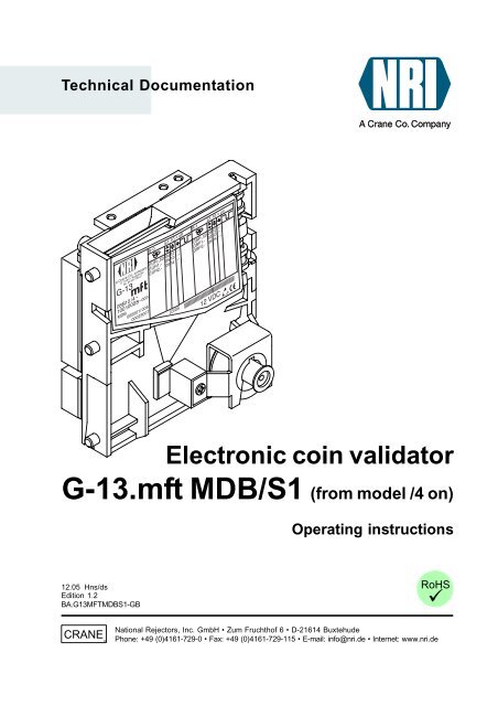
Technical Documentation<br />
Electronic coin validator<br />
G-13.mft MDB/S1 (from model /4 on)<br />
Operating instructions<br />
12.05 Hns/ds<br />
Edition 1.2<br />
BA.G13MFTMDBS1-GB<br />
CRANE<br />
<strong>National</strong> <strong>Rejectors</strong>, <strong>Inc</strong>. <strong>GmbH</strong> • Zum Fruchthof 6 • D-21614 Buxtehude<br />
Phone: +49 (0)4161-729-0 • Fax: +49 (0)4161-729-115 • E-mail: info@nri.de • Internet: www.nri.de
G-13.mft MDB/S1<br />
TABLE OF CONTENTS<br />
Table of contents<br />
1 General information 7<br />
General information about these instructions 7<br />
General information about the coin validator G-13.mft<br />
with MDB/S1 interface 8<br />
Advantages 9<br />
Models 9<br />
2 Safety instructions 10<br />
Proper use 10<br />
Protecting yourself and equipment 11<br />
3 Design 12<br />
Switching blocks 14<br />
Switch assignment with double block<br />
data-management (B-0 and B-1) 14<br />
Switch assignment with single<br />
block data-management 15<br />
Return lever and return button 15<br />
Interfaces 16<br />
Interface – vending machine 16<br />
Interface – configuration (WinEMP/PalmEMP2) 17<br />
Interface – external sorting device 17<br />
Label 18<br />
<strong>National</strong> <strong>Rejectors</strong>, <strong>Inc</strong>. <strong>GmbH</strong>, Buxtehude<br />
3
TABLE OF CONTENTS<br />
G-13.mft MDB/S1<br />
4 Function 19<br />
Coin acceptance and coin rejection 19<br />
Coin channels 20<br />
Single or double block data-management 21<br />
Accepted coin sensors 21<br />
Control for external sorting of accepted coins 22<br />
Sorting principle 22<br />
Sorting with NRI sorting device 23<br />
Sorting time of an external sorting device 23<br />
Do not accept coin types 24<br />
Inhibit all/individual coin types via vending<br />
machine control system 24<br />
Inhibit individual coin types/coin type groups on<br />
the coin validator 24<br />
5 Starting up 25<br />
Starting up in the vending machine 26<br />
Device environment for configuration software<br />
(WinEMP) 27<br />
Connection to Palm handheld (PalmEMP2) 27<br />
Installation of the NRI sorting device ... 28<br />
... on the top entry model 28<br />
... on the front entry model 30<br />
6 Operation 31<br />
Inhibit coin channels ... 31<br />
... with double block data-management (B-0 and B-1) 31<br />
... with single block data-management 33<br />
Teach mode 35<br />
Switch assignment with double block<br />
data-management (in teach mode) 35<br />
Switch assignment with single block<br />
data-management (in teach mode) 35<br />
Teach coin channels 36<br />
Select memory block<br />
(only for double block data-management) 37<br />
4 <strong>National</strong> <strong>Rejectors</strong>, <strong>Inc</strong>. <strong>GmbH</strong>, Buxtehude
G-13.mft MDB/S1<br />
TABLE OF CONTENTS<br />
7 Maintenance and service 38<br />
Cleaning coin validator 38<br />
Troubleshooting 39<br />
8 Which functions can be set using WinEMP/<br />
PalmEMP2? 40<br />
9 Technical data 41<br />
CE certification 42<br />
Pin assignment and connection diagrams 44<br />
G-13.mft – vending machine 44<br />
G-13.mft – external sorting device 46<br />
Commands, status and error messages 47<br />
Implemented MDB commands 47<br />
MDB status and error codes (reply to poll) 47<br />
Implemented S1 commands 48<br />
S1 status and error codes (reply to poll) 48<br />
S1 standard settings (following reset) 48<br />
Accessories 49<br />
Front plates 49<br />
Sorting device ... 50<br />
... for top entry model 50<br />
... for front entry model 50<br />
Configuration software 51<br />
Index 52<br />
Glossary 55<br />
<strong>National</strong> <strong>Rejectors</strong>, <strong>Inc</strong>. <strong>GmbH</strong>, Buxtehude<br />
5
G-13.mft MDB/S1<br />
INTRODUCTION<br />
1 General information<br />
This chapter should provide a general overview of the advantages and<br />
options regarding the coin validator G-13.mft with serial MDB or S1 interface.<br />
The first section, however, is designed to help you navigate easily within<br />
these operating instructions.<br />
General information about these instructions<br />
These operating instructions describe the design and operation of the<br />
electronic coin validator G-13.mft with serial MDB or S1 interface. Chapters<br />
5 und 6 explain the necessary steps for starting up and operating the coin<br />
validator. The index and glossary shorten the search for specific explanations.<br />
To make it easier for you to navigate within these instructions and to operate<br />
the device, the following accentuations were made in the text:<br />
• Safety instructions, which have to be taken note of in order to<br />
protect operators and equipment, have been written in bold and given<br />
the pictogram .<br />
• Special notes, which are to facilitate the use of the coin validator, have<br />
been written in italics and also been given a pictogram .<br />
• Requests to perform an action are numbered in another typeface.<br />
• At the beginning of a chapter you will find a short "guide", which<br />
summarizes the content of the chapter.<br />
Apart from these operating instructions there is the following technical<br />
documentation for the G-13.mft with MDB/S1 interface:<br />
• WinEMP – The configuration and diagnostics program for NRI coin<br />
validators, operating instructions for the G-13.mft<br />
• PalmEMP2 – Operating instructions for configuration of the coin<br />
validator G-13.mft<br />
• Tester G-19.0641<br />
• Electronic coin validator G-13.mft – Mounting dimensions<br />
If this documentation is not available to you, it can be downloaded<br />
at any time from the NRI homepage (www.nri.de) in a compressed<br />
PDF format.<br />
<strong>National</strong> <strong>Rejectors</strong>, <strong>Inc</strong>. <strong>GmbH</strong>, Buxtehude<br />
7
INTRODUCTION<br />
G-13.mft MDB/S1<br />
General information about the coin validator G-13.mft<br />
with MDB/S1 interface<br />
The electronic coin validator G-13.mft (multi-frequency technology) in<br />
standardized 3 1/2" format is based on the tried and tested features of the<br />
G-13.6000. Due to its modular and compact design, the G-13.mft is ideally<br />
suited for amusement, vending and service machines.<br />
The multi-frequency technology is new in the G-13.mft. It provides more<br />
flexibility for the measuring sensors, multiple scanning of the coins inserted<br />
for optimum material recognition and evaluation of 24 measuring parameters<br />
for reliable acceptance of genuine coins and separating out of false coins.<br />
Thanks to the coin validator’s flash technology software downloads to<br />
adapt the measuring technology, coin data and control software can be<br />
executed quickly and simply. The G-13.mft has 32 coin channels that can<br />
be data-managed, starting from device model /4 and higher, either in a single<br />
memory block or, when divided in 2 x 16 coin channels, in two memory<br />
blocks with different coin configurations.<br />
To be able to react as quickly as possible to new false coins and to enable<br />
you to make your individual adjustments, the coin validator can be connected<br />
to a PC programming station which is made up of the configuration and<br />
diagnostics software "WinEMP" including card reader and the tester<br />
G-19.0641. With the aid of the Palm handheld software "PalmEMP2" you<br />
can configure the coin validator directly at the machine independently of the<br />
PC.<br />
Coins that have not been taken into consideration at the manufacturer’s<br />
company can be programmed in the optional teach mode directly at the coin<br />
validator by inserting coins.<br />
8 <strong>National</strong> <strong>Rejectors</strong>, <strong>Inc</strong>. <strong>GmbH</strong>, Buxtehude
G-13.mft MDB/S1<br />
INTRODUCTION<br />
Advantages<br />
• Acceptance speed of 2 coins per second<br />
• Coin channels that can be inhibited individually or in groups<br />
• Teach mode for 8 coin channels<br />
• Operating and manipulation safety provided by optical accepted coin<br />
sensors in the coin outlet area<br />
• Interface for connection to a programming station or Palm handheld<br />
which makes immediate reaction to the use of false coins possible<br />
• Multi-frequency technology for reliable coin recognition<br />
• Flash technology for uncomplicated and time-saving firmware<br />
updates<br />
• Optional sensor for increased protection against manipulation in the<br />
cash-box chute<br />
Models<br />
The G-13.mft is available as an MDB model and as an S1 model. The S1<br />
protocol is an MDB protocol specified for NRI coin validators and differs from<br />
the standard MDB protocol with respect to commands and restrictions for<br />
mains supply and sorting.<br />
Both models of the G-13.mft are available with top or front entry. The<br />
G-13.mft with front entry usually has a MIDI front plate or a MINI front plate<br />
fitted to the left-hand side of the device (see Chap. 3 "Design"). The device<br />
is, however, also available as a front entry model without front plate.<br />
<strong>National</strong> <strong>Rejectors</strong>, <strong>Inc</strong>. <strong>GmbH</strong>, Buxtehude<br />
9
SAFETY INSTRUCTIONS<br />
G-13.mft MDB/S1<br />
2 Safety instructions<br />
Before operating the device for the first time, please read through these<br />
instructions carefully at least once, and most importantly the safety<br />
instructions. This is to ensure you have understood the contents of these<br />
instructions as well as how to operate the coin validator.<br />
Proper use<br />
Series G-13.mft coin validators with MDB or S1 interface are intended to be<br />
used in amusement, vending and service machines with an MDB or S1<br />
interface and are supposed to check the coins inserted in the machines for<br />
specific coin properties.<br />
These coin validators have been constructed in compliance with the state<br />
of the art and recognized safety regulations. Nevertheless this equipment<br />
can be a source of danger. Therefore please observe the following safety<br />
regulations.<br />
10 <strong>National</strong> <strong>Rejectors</strong>, <strong>Inc</strong>. <strong>GmbH</strong>, Buxtehude
G-13.mft MDB/S1<br />
SAFETY INSTRUCTIONS<br />
Protecting yourself and equipment<br />
The coin validator may only be connected by a qualified<br />
electrician.<br />
Only use the coin validator according to proper use. Under no<br />
circumstances can the manufacturer be held liable for any<br />
damage or loss resulting from improper use of the device.<br />
The coin validator PCB is fitted with components which may<br />
be damaged beyond repair by electrostatic discharge. Please<br />
observe the handling instructions for components exposed to<br />
the risk of electrostatic discharge.<br />
Pull out the vending machine’s mains plug before you install,<br />
clean or remove the coin validator.<br />
Select the correct voltage for the coin validator (see label).<br />
Ensure the correct potential equalization in the vending<br />
machine.<br />
Never pull the connecting cable of the coin validator from the<br />
vending machine when a voltage is applied.<br />
Contact NRI if you wish to alter the construction of the device<br />
to a greater extent than that described in these instructions.<br />
Keep water and other liquids away from the coin validator.<br />
If the device is no longer required, please dispose of it<br />
correctly.<br />
We reserve the right to make technical modifications to the<br />
device which are not covered by these instructions.<br />
<strong>National</strong> <strong>Rejectors</strong>, <strong>Inc</strong>. <strong>GmbH</strong>, Buxtehude<br />
11
DESIGN<br />
G-13.mft MDB/S1<br />
3 Design<br />
2<br />
1<br />
1<br />
2<br />
3<br />
3<br />
6<br />
7<br />
3<br />
3<br />
10 9<br />
8<br />
3<br />
3<br />
4<br />
5<br />
Fig. 1a: Design – G-13.mft, top entry model<br />
1 Return lever<br />
2 Coin insert funnel<br />
3 Mounting studs<br />
4 Coin outlet – return area<br />
5 Coin outlet – cash-box<br />
6 Switching blocks<br />
7 Interface – vending machine, cctalk<br />
(not assigned)<br />
8 Interface – vending machine<br />
9 Interface – external sorting<br />
10 Interface –<br />
PC programming station (WinEMP)/<br />
Palm handheld (PalmEMP2)<br />
12 <strong>National</strong> <strong>Rejectors</strong>, <strong>Inc</strong>. <strong>GmbH</strong>, Buxtehude
G-13.mft MDB/S1<br />
DESIGN<br />
1<br />
5<br />
MINI<br />
2<br />
3<br />
6<br />
7<br />
3<br />
3<br />
10 9<br />
8<br />
1<br />
3<br />
5<br />
5<br />
MIDI<br />
4<br />
Fig. 1b: Design – G-13.mft, front entry model with front plate<br />
1 Return button<br />
2 Coin insert funnel<br />
3 Mounting studs<br />
4 Coin outlet – cash-box<br />
5 Coin outlet – return area<br />
6 Switching blocks<br />
7 Interface – vending machine, cctalk<br />
(not assigned)<br />
8 Interface – vending machine<br />
9 Interface – external sorting<br />
10 Interface –<br />
PC programming station (WinEMP)/<br />
Palm handheld (PalmEMP2)<br />
<strong>National</strong> <strong>Rejectors</strong>, <strong>Inc</strong>. <strong>GmbH</strong>, Buxtehude<br />
13
DESIGN<br />
G-13.mft MDB/S1<br />
Coins inserted into the coin validator pass through the coin insert funnel 2<br />
into the measurement and validation area of the device, in which their coin<br />
properties are compared with the values of the stored acceptance bands.<br />
Coins rejected by the coin validator pass into the return area 4, Fig. 1a/5,<br />
Fig. 1b, and coins accepted for sale leave the device through the coin<br />
outlet 5, Fig. 1a/4, Fig. 1b, and are fed into the cash-box or an external<br />
sorting device. (See Fig. 1a and 1b)<br />
Switching blocks<br />
On the rear, the coin validator is equipped with<br />
two switching blocks with 10 DIL switches<br />
S1.1-10 and S2.1-10 each.<br />
S1<br />
S2<br />
Depending whether your device was programmed for coin data-management<br />
according to a factory-made setting for one or two memory blocks (B-0 and<br />
B-1, see label), the DIL switches will have different functions (see also<br />
section "Single or double block data-management" in Chap. 4 "Function").<br />
On the rear of the device you will find a brief description of the<br />
individual switch functions.<br />
Switch assignment with double block data-management (B-0 and B-1)<br />
Coin channels or the coin types assigned to the coin channels can be<br />
individually inhibited using the first eight DIL switches of the upper switching<br />
block S1 and the lower switching block S2 (see section "Inhibit coin<br />
channels" in Chap. 6 "Operation").<br />
The ninth DIL switch of the upper switching block S1 does not have any<br />
function.<br />
The tenth DIL switch of the upper switching block S1 is used to select the<br />
memory block (see section "Select memory block" in Chap. 6 "Operation").<br />
The lower switching block S2 is used to teach coin types or tokens in the<br />
teach mode (see section "Teach mode" in Chap. 6 "Operation").<br />
14 <strong>National</strong> <strong>Rejectors</strong>, <strong>Inc</strong>. <strong>GmbH</strong>, Buxtehude
G-13.mft MDB/S1<br />
DESIGN<br />
Switch assignment with single block data-management<br />
Coin channels or the coin types assigned to the coin channels can be<br />
inhibited using the first eight DIL switches of the upper switching block S1.<br />
To do this the DIL switches are assigned a coin channel randomly. A group<br />
of selected coin channels can be assigned to a switch to inhibit a number<br />
of coin channels (see section "Inhibit coin channels" in Chap. 6 "Operation").<br />
The ninth and tenth DIL switches of the upper switching block S1 do not have<br />
any function.<br />
The lower switching block S2 is used to teach coin types or tokens in the<br />
teach mode (see section "Teach mode" in Chap. 6 "Operation") and to inhibit<br />
these taught coins in the normal operating mode.<br />
Return lever and return button<br />
The return lever (1, Fig. 1a) on the top of the device is operated using the<br />
return button on the vending machine if the coins which have already been<br />
inserted are to be returned or a jam caused, e.g., by coins which have<br />
become stuck needs to be removed. Operating the return lever opens the<br />
measurement and validation area of the coin validator so that all objects in<br />
the coin validator are transported into the return area.<br />
Devices with front entry through a front plate do not have a return lever. Here<br />
the measurement and validation area is opened by pressing the return<br />
button (1, Fig. 1b) on the front plate.<br />
<strong>National</strong> <strong>Rejectors</strong>, <strong>Inc</strong>. <strong>GmbH</strong>, Buxtehude<br />
15
DESIGN<br />
G-13.mft MDB/S1<br />
Interfaces<br />
At the bottom right-hand side on the rear of the coin validator there is a<br />
10-pole connecting plug to the vending machine, and on the left-hand side<br />
at the centre there is a 3-pole JST plug for connecting an external sorting<br />
device. On the left-hand side, there is the interface to the PC programming<br />
station and the Palm handheld. (See Fig. 1a and 1b)<br />
Interface – vending machine<br />
The coin validator is connected to the machine via the serial MDB interface 8<br />
(see Fig. 1a and 1b) and a 10-pole cable via which it can receive information<br />
from the vending machine or send information to the vending machine. The<br />
machine operates as a master and the G-13.mft as a slave. The master can<br />
communicate with several slaves (e.g. coin and bill validator). To ensure<br />
unambiguous communication each device has its own MDB address. The<br />
address of the G-13.mft as an MDB model is "01", and "15" as an S1 model.<br />
The G-13.mft as an MDB model does not fulfil the MDB specification<br />
on two counts, i.e. the specified voltage range and the electrical<br />
isolation of the communication lines.<br />
If a supply voltage of 42 V max. and electrical isolation are<br />
desirable, an MDB converter G-55.0360 can be ordered from NRI<br />
(ordering code 23627).<br />
You can obtain further information about the MDB and S1 interface:<br />
• in the "NAMA document MDB/ICP 2.0" (www.vending.org) and<br />
• in the NRI S1 specification for the G-40 S1, which will be placed at<br />
your disposal upon your request.<br />
You will find a list of the commands implemented in the G-13.mft in<br />
Chap. 9 "Technical data".<br />
Please refer to the section "Pin assignment and connection<br />
diagrams" also included in Chap. 9 "Technical data" for more details<br />
on the assignment of individual plugs (pins).<br />
16 <strong>National</strong> <strong>Rejectors</strong>, <strong>Inc</strong>. <strong>GmbH</strong>, Buxtehude
G-13.mft MDB/S1<br />
DESIGN<br />
Interface – configuration (WinEMP/PalmEMP2)<br />
To configure the coin validator the device is connected to a PC or a mobile<br />
Palm handheld. For this purpose the G-13.mft has on the right-hand side a<br />
10-pole PCB direct plug 10 (see Fig. 1a und 1b), which can be used to<br />
connect the coin validator to the PC via a tester and card reader or to a Palm<br />
handheld (see Chap. 5 "Starting up"). The device is set by means of the<br />
configuration and diagnostics software WinEMP or PalmEMP2 (see separate<br />
software instructions).<br />
Interface – external sorting device<br />
On the rear of the device, there is a 3-pole JST plug 9 (see Fig. 1a and 1b).<br />
This plug can be used to control sorting gates for sorting inserted coins (see<br />
sections "Control for external sorting of accepted coins" in Chap. 4 "Function"<br />
and "Pin assignment and connection diagrams" in Chap. 9 "Technical<br />
data").<br />
The 3-pole sorting plug is made by the JST company and has the<br />
type designation "ZH connector", 1.5 mm. You can obtain further<br />
information about the plug at the Internet address www.JST.com.<br />
<strong>National</strong> <strong>Rejectors</strong>, <strong>Inc</strong>. <strong>GmbH</strong>, Buxtehude<br />
17
DESIGN<br />
G-13.mft MDB/S1<br />
Label<br />
The label of the coin validator contains all the data defining the device such<br />
as device series, device type and device operation as well as customerspecific<br />
default values such as coin type and currency:<br />
1 2 3 4<br />
5 6 7<br />
16<br />
15<br />
14<br />
13<br />
12 11<br />
10<br />
9<br />
8<br />
Fig. 2: Label<br />
1 Coin information – memory block 0<br />
(if DIL switch S1.10 on OFF)<br />
2 Currency and coin type – memory<br />
block 0<br />
3 Channel number, normal coin<br />
channel – memory block 0<br />
4 Channel number, narrow coin channel<br />
– memory block 0<br />
5 Channel number, very narrow coin<br />
channel – memory block 0<br />
6 not assigned<br />
7 Coin information – memory block 1<br />
(if DIL switch S1.10 on ON)<br />
8 Nominal voltage<br />
9 Bar code<br />
10 Date of manufacture<br />
11 Consecutive device number per order<br />
number<br />
12 Ordering code<br />
13 Order number<br />
14 Device model<br />
15 Data block number and revision<br />
number<br />
16 Device type<br />
9B = Front entry model without front plate<br />
8B = Front entry model with MINI front plate<br />
7B = Front entry model with MIDI front plate<br />
6B = Top entry model<br />
18 <strong>National</strong> <strong>Rejectors</strong>, <strong>Inc</strong>. <strong>GmbH</strong>, Buxtehude
G-13.mft MDB/S1<br />
FUNCTION<br />
4 Function<br />
This chapter describes how the coin validator works, using the route which<br />
an inserted coin takes in the coin validator:<br />
• Coin acceptance and coin rejection<br />
• Coin channels<br />
• Single or double block data-management<br />
• Accepted coin sensors<br />
• Optional string recognition<br />
• Control for external sorting device<br />
• Inhibit coin acceptance<br />
Coin acceptance and coin rejection<br />
Coins inserted into the coin validator pass inductive and optical sensors<br />
which check the coins and there they generate individual measurement<br />
values. Due to the special design and arrangement of these sensors, each<br />
coin is checked for its material properties and dimensions. An upper limit<br />
and a lower limit are stored for each coin type, a so-called acceptance band<br />
so that the coin validator knows whether to accept a coin or not. If the<br />
measured values or the coin are within the acceptance band, the coin is<br />
accepted for sale when it has passed the acceptance gate and accepted<br />
coin sensors, but if they are outside the band, it is rejected and directed into<br />
the return area.<br />
The limit values of the acceptance bands are programmed by the<br />
manufacturer according to the customers’ specifications, but can be<br />
adjusted with the WinEMP PC configuration software or PalmEMP2.<br />
Following a reset operation, the coin acceptance function is disabled<br />
and must be enabled again by the vending machine.<br />
As a standard feature, the G-13.mft refuses each further<br />
acceptance of a coin if the G-13.mft has not been activated by the<br />
vending machine within the last 2 seconds or if the last accepted<br />
coin has not yet been scanned by the vending machine.<br />
<strong>National</strong> <strong>Rejectors</strong>, <strong>Inc</strong>. <strong>GmbH</strong>, Buxtehude<br />
19
FUNCTION<br />
G-13.mft MDB/S1<br />
Coin channels<br />
The coin validator has 32 "memory slots" for coin acceptance which can be<br />
assigned up to 32 different coin types or tokens. These "memory slots" are<br />
termed coin channels. The acceptance band of a coin type/token is allocated<br />
to a coin channel and the coin type/token is accepted in that channel.<br />
In order to reject false coins reliably, frequently for one coin type, in addition to<br />
the normal coin channel, channels with a narrow or even very narrow<br />
acceptance band are set up (see section "Label" in Chap. 3 "Design"). The<br />
limit values of these coin channels are closer to one another so that false coins<br />
with similar measured values are rejected. Narrow and very narrow coin<br />
channels, however, also possess a lower acceptance rate.<br />
In addition, it is possible to allocate coins with different measured values but<br />
identical coin values to different coin channels. This is how the coin validator<br />
can, for example, accept old and new coins of the same type.<br />
However, a coin channel is not only assigned the acceptance band of a coin<br />
type but also other coin information which defines further processing of the<br />
coin after its acceptance: e.g. coin value or sorting information for an<br />
external sorting device.<br />
Since in most cases the manufacturer’s customer-specific programming<br />
does not take up all the coin channels, channels which are still vacant can<br />
be assigned coin types and further information desired at any time using the<br />
WinEMP PC configuration software or PalmEMP2. Existing configurations<br />
can be changed.<br />
The last eight coin channels 25 to 32 (or 9 to 16 with double block datamanagement,<br />
see section "Single or double block data-management" in<br />
this chapter) are intended to be used for the teach mode. In these coin<br />
channels new coin types can also be taught without configuration software,<br />
directly via the lower switching block on the coin validator; i.e. a coin channel<br />
is re-assigned a coin type or also a token (see section "Teach mode" in<br />
Chap. 6 "Operation").<br />
20 <strong>National</strong> <strong>Rejectors</strong>, <strong>Inc</strong>. <strong>GmbH</strong>, Buxtehude
G-13.mft MDB/S1<br />
FUNCTION<br />
Single or double block data-management<br />
At the manufacturer’s company, a customer-specific setting is programmed<br />
to determine whether the 32 coin channels are to be data-managed in one<br />
memory block or, when divided into 16 channels each, in two memory<br />
blocks (double block data-management).<br />
If the double block data-management has been configured, the G-13.mft can<br />
data-manage two separately programmed (memory) blocks 0 and 1 (see<br />
label). The 16 coin channels can be assigned to each block with different<br />
coin types (also currencies), sorting information, etc. Only one block can be<br />
active at a time and be used for the coin measurement and for further coin<br />
processing. You can use the upper switching block on the device to select<br />
the desired block (see section "Select memory block" in Chap. 6 "Operation").<br />
Accepted coin sensors<br />
To ensure that accepted coins actually arrive in the cash-box or in an<br />
external sorting device and that coin acceptance has not been tampered<br />
with, accepted coin sensors, positioned in front of the cash-box coin outlet<br />
check whether the inserted coin drops unhindered into the cash-box chute.<br />
A coin signal is not transmitted to the vending machine until the coin has<br />
passed this checking function.<br />
If the accepted coin sensors are continuously covered, e.g. by a coin pileup,<br />
coin acceptance is inhibited.<br />
<strong>National</strong> <strong>Rejectors</strong>, <strong>Inc</strong>. <strong>GmbH</strong>, Buxtehude<br />
21
FUNCTION<br />
G-13.mft MDB/S1<br />
Control for external sorting of accepted coins<br />
In order to be able to guide the accepted coins into the cash-box or, e.g., into<br />
change tubes or hoppers, you can equip the coin validator with the NRI sorting<br />
device or with another sorting device. A larger sorting device can be connected<br />
to the S1 model due to the fact that up to eight sorting ways can be used.<br />
Sorting principle<br />
The sorting gates are activated via the 3-pole JST plug on the rear of the<br />
device (see Fig. 1a and 1b) and via three sorting control lines. Since these<br />
are bidirectional sorting control lines, the coin validator can also receive<br />
signals. If, for example, a connected hopper or change tube is full of coins<br />
and if these units send an appropriate "Full" signal to the coin validator, all<br />
the other coins are directed into the cash-box until the hopper/change tube<br />
is emptied or an amount has been paid out. With the S1 model, this kind of<br />
feedback from an external sorting device can only be provided on sorting<br />
ways that are addressed via a single sorting control line (S1 sorting way 1,<br />
2, 4; see table below).<br />
Which coin type is to be sorted via which of the three sorting control lines is<br />
programmed by the manufacturer according to the customers’ specifications<br />
but it can be changed or re-configured with the WinEMP PC configuration<br />
software or PalmEMP2.<br />
While the coin validator is sorting an accepted coin (= sorting time,<br />
see section "Sorting time of an external sorting device" in this<br />
chapter), it cannot accept any further coins.<br />
With the S1 model, the following sorting control lines are activated for a<br />
specific sorting way:<br />
S1 sorting way Sorting control line "Tube full message"<br />
1 2 3<br />
0 (cash-box) – – – no<br />
1X – – yes<br />
2 – X – yes<br />
3 X X – no<br />
4 – – X yes<br />
5 X – X no<br />
6 – X X no<br />
7 X X X no<br />
22 <strong>National</strong> <strong>Rejectors</strong>, <strong>Inc</strong>. <strong>GmbH</strong>, Buxtehude
G-13.mft MDB/S1<br />
FUNCTION<br />
Sorting with NRI sorting device<br />
When the optional NRI sorting device<br />
is used (see also section<br />
"Accessories" in Chap. 9 "Technical<br />
data"), the individual coin types can<br />
be distributed regardless of their<br />
dimensions among the three sorting<br />
chutes. Each chute can be defined<br />
as a cash-box chute.<br />
For details on how to connect<br />
the NRI sorting device to<br />
the coin validator, see<br />
Chap. 5 "Starting up".<br />
Sorting chute<br />
The following table shows which<br />
sorting control line must be<br />
activated in order to sort coins<br />
into a specific sorting chute:<br />
Sorting control line<br />
Left 1<br />
Middle –<br />
Right 2<br />
R<br />
L<br />
M<br />
Sorting time of an external sorting device<br />
For the switching time of an external sorting device, you can set a sorting<br />
time using the WinEMP PC configuration software or PalmEMP2.<br />
<strong>National</strong> <strong>Rejectors</strong>, <strong>Inc</strong>. <strong>GmbH</strong>, Buxtehude<br />
23
FUNCTION<br />
G-13.mft MDB/S1<br />
Do not accept coin types<br />
If coins are no longer to be accepted for payment at the vending machine,<br />
you can inhibit coin acceptance using either the vending machine control<br />
system or the coin validator.<br />
Inhibit all/individual coin types via vending machine control system<br />
The vending machine can inhibit all coin acceptance. Then the coin validator<br />
no longer accepts coins. However, the vending machine can also inhibit only<br />
specific coin types, e.g., if there is no more change in an external payout<br />
device or a coin type is very frequently replaced by false coins.<br />
For details on how these functions are programmed, please refer to "NAMA<br />
document MDB/ICP 2.0" (www.vending.org) or to the NRI S1 specification<br />
for the G-40 S1, which we will be pleased to place at your disposal on<br />
request.<br />
Inhibit individual coin types/coin type groups on the coin validator<br />
As an alternative to the individual inhibiting of specific coin types using the<br />
vending machine, you can inhibit individual coin types or even groups of coin<br />
types on site using the DIL switches on the coin validator (see section "Inhibit<br />
coin channels" in Chap. 6 "Operation").<br />
If individual coin types are to be inhibited on a long-term basis, you<br />
can use WinEMP or PalmEMP2 to deactivate the respective coin<br />
channels without being required to delete the individual<br />
configuration. This individual configuration remains available and<br />
can be reactivated again later.<br />
24 <strong>National</strong> <strong>Rejectors</strong>, <strong>Inc</strong>. <strong>GmbH</strong>, Buxtehude
G-13.mft MDB/S1<br />
STARTING UP<br />
5 Starting up<br />
The G-13.mft is either<br />
• started up in a machine, or<br />
• connected for configuration of the device with the NRI software<br />
– to a PC and to an NRI tester for configuration with the software<br />
WinEMP or<br />
– to a Palm handheld for configuration with the software PalmEMP2<br />
in the machine.<br />
In the last section of this chapter, you can find out how to fit the NRI sorting<br />
device to the G-13.mft before you install the device in the vending machine.<br />
<strong>National</strong> <strong>Rejectors</strong>, <strong>Inc</strong>. <strong>GmbH</strong>, Buxtehude<br />
25
STARTING UP<br />
G-13.mft MDB/S1<br />
Starting up in the vending machine<br />
Install the MDB model of the G-13.mft in vending machines with an MDB<br />
interface and the S1 model in vending machines with an appropriate S1<br />
interface:<br />
1 If necessary, install the sorting device on the coin validator (see<br />
section "Installation of the NRI sorting device ..." in this chapter).<br />
2 Disconnect the machine from the mains supply.<br />
3 Hang the coin validator in the vending machine mount using the lateral<br />
mounting studs 1 (see Fig. 3).<br />
4 Connect the coin validator to the machine using the 10-pole interface 3<br />
provided and the appropriate connecting cable (see Fig. 3).<br />
5 Reconnect the mains supply to the machine.<br />
Make sure the correct supply voltage is connected (see label).<br />
The G-13.mft as an MDB model does not fulfil the MDB specification<br />
on two counts, i.e. the specified voltage range and the electrical<br />
isolation of the communication lines.<br />
If a supply voltage of 42 V max. and electrical isolation are<br />
desirable, an MDB converter G-55.0360 can be ordered from NRI<br />
(ordering code 23627).<br />
1<br />
1<br />
2<br />
3<br />
1<br />
1 Mounting studs<br />
(not illustrated on the left-hand side of the device)<br />
2 Interface –<br />
PC programming station (WinEMP)/<br />
Palm handheld (PalmEMP2)<br />
3 Interface – vending machine<br />
Fig. 3: Installation<br />
26 <strong>National</strong> <strong>Rejectors</strong>, <strong>Inc</strong>. <strong>GmbH</strong>, Buxtehude
G-13.mft MDB/S1<br />
STARTING UP<br />
Device environment for configuration software (WinEMP)<br />
If you want the G-13.mft to be set on the PC using the diagnostics and<br />
configuration software WinEMP, the following device environment is<br />
connected to the PCB direct plug 2 of the coin validator (see Fig. 3 and<br />
section "Accessories" in Chap. 9 "Technical data"):<br />
• Tester G-19.0641<br />
• Card reader G-19.0647 incl. chip card<br />
WinEMP<br />
Card reader<br />
Tester<br />
G-13.mft<br />
Fig. 4: Connect G-13.mft to PC<br />
To find out how to connect this device environment to your PC, please refer<br />
to the separate operating instructions for the WinEMP software "WinEMP –<br />
The configuration and diagnostics program for NRI coin validators" (refer<br />
also to Chap. 8 "Which functions can be set using WinEMP/PalmEMP2?").<br />
Connection to Palm handheld (PalmEMP2)<br />
With a Palm handheld and the NRI software PalmEMP2 the G-13.mft can<br />
be directly configured on site inside the machine. The PalmEMP2 program<br />
is available on the NRI homepage. To be able to connect your Palm handheld<br />
to the coin validator, you need an NRI dongle (see section "Accessories" in<br />
Chap. 9 "Technical data"). A connecting cable is part of the scope of delivery.<br />
Should you wish the memory blocks of the G-13.mft to be updated and for<br />
this a data block download to be performed, a WinEMP licence with<br />
PalmEMP2 download rights must be additionally ordered (see above and<br />
the section "Accessories" in Chap. 9 "Technical data"). Having done this, the<br />
new data blocks can be loaded initially into the Palm handheld, using<br />
WinEMP from your PC’s internal hard disk, then from the Palm handheld into<br />
the coin validator.<br />
To find out how to connect the Palm handheld to the PCB direct plug 2 (see<br />
Fig. 3) and how to install and operate PalmEMP2, please refer to the<br />
separate operating instructions for the software (refer also to Chap. 8<br />
"Which functions can be set using WinEMP/PalmEMP2?").<br />
<strong>National</strong> <strong>Rejectors</strong>, <strong>Inc</strong>. <strong>GmbH</strong>, Buxtehude<br />
27
STARTING UP<br />
G-13.mft MDB/S1<br />
Installation of the NRI sorting device ...<br />
If you want to operate the G-13.mft with the NRI sorting device, you must use<br />
a special bracket to install the NRI sorting device on the top entry model or<br />
on the front entry model:<br />
... on the top entry model<br />
1 If necessary, fasten chute extension 1 with screw 2 to sorting<br />
device 3 (see Fig. 5a).<br />
2 Fasten mounting frame 4 by means of screws 5 and 6 to the rear of<br />
the sorting device.<br />
3 Hang the coin validator by its mounting studs 7 in the mounting<br />
frame.<br />
4 Use the 3-pole sorting plug 8 on the PCB 9 and on the rear of the<br />
coin validator to connect the sorting device to the G-13.mft with the<br />
help of the appropriate sorting cable.<br />
5 Use the 10-pole connecting plug 10 on the PCB 9 and on the rear of<br />
the coin validator to connect the sorting device to the G-13.mft for<br />
power supply of the sorting solenoids with the help of the appropriate<br />
connecting cable.<br />
6 Use the 10-pole connecting plug 10 on the PCB 9 and the same<br />
connecting cable to connect the coin validator to the vending<br />
machine (see also section "Starting up in the vending machine" in<br />
this chapter).<br />
28 <strong>National</strong> <strong>Rejectors</strong>, <strong>Inc</strong>. <strong>GmbH</strong>, Buxtehude
G-13.mft MDB/S1<br />
STARTING UP<br />
4<br />
6<br />
5<br />
7<br />
7<br />
1<br />
3<br />
2<br />
9<br />
8<br />
10<br />
Fig. 5a: Connect G-13.mft, top entry model, to NRI sorting device<br />
<strong>National</strong> <strong>Rejectors</strong>, <strong>Inc</strong>. <strong>GmbH</strong>, Buxtehude<br />
29
STARTING UP<br />
G-13.mft MDB/S1<br />
... on the front entry model<br />
1 If necessary, fasten holding plate 1 with two screws 2 and 3 to<br />
sorting device 4 (see Fig. 5b).<br />
2 Remove screw 5 from coin validator.<br />
3 Use the holding plate to insert the sorting device from the right-hand<br />
side onto the coin validator.<br />
4 Fasten the sorting device with screw 5 to the coin validator.<br />
5 Use the 3-pole sorting plug 6 on the PCB 7 and on the rear of the<br />
coin validator to connect the sorting device to the G-13.mft with the<br />
help of the appropriate sorting cable.<br />
6 Use the 10-pole connecting plug 8 on the PCB 7 and on the rear of<br />
the coin validator to connect the sorting device to the G-13.mft for<br />
power supply of the sorting solenoids with the help of the appropriate<br />
connecting cable.<br />
7 Use the 10-pole connecting plug 8 on the PCB 7 and the same<br />
connecting cable to connect the coin validator to the vending<br />
machine (see also section "Starting up in the vending machine" in<br />
this chapter).<br />
4<br />
1<br />
5<br />
2<br />
3<br />
7<br />
6<br />
8<br />
Fig. 5b: Connect G-13.mft, front entry model,<br />
to NRI sorting device<br />
30 <strong>National</strong> <strong>Rejectors</strong>, <strong>Inc</strong>. <strong>GmbH</strong>, Buxtehude
G-13.mft MDB/S1<br />
OPERATION<br />
6 Operation<br />
In this chapter you will find out how to:<br />
• Inhibit coin types or their coin channels<br />
• Teach coin types in teach mode<br />
• Select the desired memory block 0 or 1<br />
Inhibit coin channels ...<br />
Depending whether the 32 coin channels are being data-managed in one or,<br />
when divided in 16 coin channels each, in two memory blocks (B-0 and B-1,<br />
see label), the coin types are inhibited differently.<br />
... with double block data-management (B-0 and B-1)<br />
Using the first eight DIL switches of the two switching blocks S1 and S2 on<br />
the rear of the coin validator each of the 16 coin channels or each coin type<br />
assigned to a specific coin channel can be inhibited individually, i.e. this coin<br />
type is not accepted for payment on the vending machine.<br />
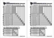
The 16 DIL switches inhibit the following coin channels:<br />
Switching block S1<br />
DIL switch off on<br />
1Coin channel 1vacant inhibited<br />
2 Coin channel 2 vacant inhibited<br />
3 Coin channel 3 vacant inhibited<br />
4 Coin channel 4 vacant inhibited<br />
5 Coin channel 5 vacant inhibited<br />
6 Coin channel 6 vacant inhibited<br />
7 Coin channel 7 vacant inhibited<br />
8 Coin channel 8 vacant inhibited<br />
S1<br />
S2<br />
Switching block S2<br />
DIL switch off on<br />
1Coin channel 9 vacant inhibited<br />
2 Coin channel 10 vacant inhibited<br />
3 Coin channel 11 vacant inhibited<br />
4 Coin channel 12 vacant inhibited<br />
5 Coin channel 13 vacant inhibited<br />
6 Coin channel 14 vacant inhibited<br />
7 Coin channel 15 vacant inhibited<br />
8 Coin channel 16 vacant inhibited<br />
S1<br />
S2<br />
<strong>National</strong> <strong>Rejectors</strong>, <strong>Inc</strong>. <strong>GmbH</strong>, Buxtehude<br />
31
OPERATION<br />
G-13.mft MDB/S1<br />
Please refer to the label of the device to see which coin type has been<br />
assigned to which coin channel at the factory. However, this assignment<br />
can be changed at any time using the WinEMP PC configuration software<br />
or PalmEMP2.<br />
If all coin types are to be accepted for payment at the vending machine, the<br />
DIL switches S1.1–S1.8 and S2.1–S2.8 of the two switching blocks are in<br />
the lower position on OFF. If you want to inhibit a coin channel, you only need<br />
to move the respective DIL switch toward the top to ON.<br />
Example<br />
(the coin validator is no longer supposed to accept the coin(s) assigned to coin<br />
channels 3 and 10, which means that coin channels 3 and 10 must be<br />
inhibited)<br />
With the DIL switches in these positions, the coin validator no longer<br />
accepts the coin type(s) assigned to coin channels 3 and 10!<br />
If a normal coin channel and a narrow coin channel have been<br />
programmed on the coin validator for one coin type, the normal coin<br />
channel must be inhibited as described above in order to activate<br />
the narrow coin channel. If both channels are activated, the wider<br />
acceptance band of the normal coin channel is used.<br />
If a coin type is to be inhibited, both coin channels must be<br />
inhibited.<br />
32 <strong>National</strong> <strong>Rejectors</strong>, <strong>Inc</strong>. <strong>GmbH</strong>, Buxtehude
G-13.mft MDB/S1<br />
OPERATION<br />
... with single block data-management<br />
Coin channels can be inhibited using the first eight DIL switches S1.1–S1.8<br />
of the upper switching block on the rear of the device. To do this the DIL<br />
switches are assigned a coin channel randomly. Several coin channels can<br />
also be assigned to one switch. This switch will then inhibit a coin group (e.g.<br />
all coin channels of a currency, all coin channels of a coin type (normal and<br />
narrow coin channels)).<br />
The assignment of DIL switches to coin type/coin group is programmed at<br />
the factory on a customer-specific basis. However, this setting can be<br />
changed with the WinEMP PC configuration software or PalmEMP2.<br />
If all coin types assigned to the DIL switches are to be accepted for payment<br />
at the vending machine, the DIL switches must be in the lower position (on<br />
OFF).<br />
If you want to inhibit a coin channel, you only need to move the respective DIL<br />
switch toward the top to ON.<br />
The following examples are designed to illustrate the procedure using the<br />
label. The label shows the manufacturer’s assignment of coin type/coin<br />
group.<br />
Any coin types or tokens that may have been taught in coin<br />
channels 25 to 32 are inhibited using the DIL switches of the lower<br />
switching block S2 in the assignment according to which they were<br />
taught (see section "Teach mode" in this chapter).<br />
<strong>National</strong> <strong>Rejectors</strong>, <strong>Inc</strong>. <strong>GmbH</strong>, Buxtehude<br />
33
OPERATION<br />
G-13.mft MDB/S1<br />
Example – Inhibit a currency as coin group<br />
(the coin validator must only accept euros and no longer the British currency)<br />
With this setting the coin validator only accepts euros.<br />
Example – Activate narrow acceptance bands/coin channels as coin group<br />
(the coin validator must accept the 1-euro coin and the British 1-pound coin in the<br />
narrow acceptance band and not in the normal one, i.e. it must inhibit the normal<br />
acceptance band)<br />
With this setting the coin validator accepts coins in the narrow coin channel and<br />
not in the normal one.<br />
Example – Inhibit single coin type<br />
(the coin validator must no longer accept the 2-euro coin or the British 2-pound coin)<br />
With this setting the coin validator no longer accepts the 2-euro coin or the British<br />
2-pound coin.<br />
At a coin validator with the label described above, it would also be<br />
possible to inhibit the euro currency via DIL switch S1.4.<br />
With the aid of several DIL switches more than one coin type or coin<br />
group can be inhibited simultaneously.<br />
34 <strong>National</strong> <strong>Rejectors</strong>, <strong>Inc</strong>. <strong>GmbH</strong>, Buxtehude
G-13.mft MDB/S1<br />
OPERATION<br />
Teach mode<br />
Coin channels can also be taught directly without configuration software via<br />
the switching block on the coin validator, i.e. a coin channel is reassigned a<br />
coin type or even a token without having to remove the coin validator from<br />
the vending machine. You can also widen the acceptance band for the<br />
selected coin channel so that the rejection of genuine coins is reduced. For<br />
the teaching procedure, coin channels 9 to 16 of the activated memory block<br />
are available with double block data-management and coin channels 25 to<br />
32 with single block data-management (see also section "Single or double<br />
block data-management" in Chap. 4 "Function").<br />
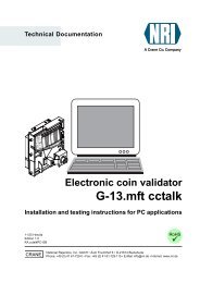
Switch assignment with double block data-management (in teach mode)<br />
Switching block S2<br />
DIL switch off on<br />
1Coin channel 9 – teach<br />
2 Coin channel 10 – teach<br />
3 Coin channel 11 – teach<br />
4 Coin channel 12 – teach<br />
5 Coin channel 13 – teach<br />
6 Coin channel 14 – teach<br />
7 Coin channel 15 – teach<br />
8 Coin channel 16 – teach<br />
9 Teach mode switch off switch on<br />
10 Acceptance band normal wide<br />
S1<br />
S2<br />
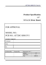
Switch assignment with single block data-management (in teach mode)<br />
Switching block S2<br />
DIL switch off on<br />
1Coin channel 25 – teach<br />
2 Coin channel 26 – teach<br />
3 Coin channel 27 – teach<br />
4 Coin channel 28 – teach<br />
5 Coin channel 29 – teach<br />
6 Coin channel 30 – teach<br />
7 Coin channel 31– teach<br />
8 Coin channel 32 – teach<br />
9 Teach mode switch off switch on<br />
10 Acceptance band normal wide<br />
S1<br />
S2<br />
<strong>National</strong> <strong>Rejectors</strong>, <strong>Inc</strong>. <strong>GmbH</strong>, Buxtehude<br />
35
OPERATION<br />
G-13.mft MDB/S1<br />
Teach coin channels<br />
To assign a coin type to a new coin channel, please proceed as follows:<br />
If you want to use the lower switching block to inhibit individual<br />
coins, remember the current switch settings so that you can restore<br />
them easily for the normal operating mode at the end.<br />
1 Set all DIL switches 1–10 of the lower<br />
switching block toward the bottom to OFF.<br />
2 Set DIL switch S2.9 toward the top to ON.<br />
Now the device is in teach mode to teach<br />
the coin channels.<br />
3 Release the coin channel to be taught<br />
(9–16 or 25–32, here: 11 or 27) by setting<br />
the appropriate DIL switch (S2.1–8, here:<br />
S2.3) toward the top to ON.<br />
4 Insert at least 10 coins of the new coin type/token into the coin<br />
validator or vending machine.<br />
After the 10 th coin has been inserted, the acceptance gate is<br />
operated once (solenoid attraction sound). Additional coins can be<br />
inserted.<br />
Now you can save the measured values generated by the inserted coins in<br />
either a normal (a) or a wide (b) acceptance band. A wide acceptance band<br />
is only an appropriate choice when you only have a limited selection of coins<br />
at your disposal for the purpose of teaching tokens and would still like to<br />
program greater tolerance limits.<br />
To save with the normal acceptance band:<br />
5a) Set DIL switch S2.9 toward the bottom<br />
to OFF.<br />
Successful saving is signalled by the<br />
acceptance gate attracting once, an<br />
error when saving is indicated by the acceptance gate attracting<br />
twice, if, for example, the acceptance band of the coins inserted and<br />
an acceptance band of an already programmed coin channel overlap.<br />
To abort the operation, first set the DIL switch of the respective coin<br />
channel (here: S2.3) and then DIL switch S2.9 toward the bottom to<br />
OFF.<br />
36 <strong>National</strong> <strong>Rejectors</strong>, <strong>Inc</strong>. <strong>GmbH</strong>, Buxtehude
G-13.mft MDB/S1<br />
OPERATION<br />
To save with a wide acceptance band:<br />
5b) Set DIL switch S2.10 toward the top to<br />
ON.<br />
The acceptance band has been<br />
widened.<br />
Now you can set DIL switch S2.9<br />
toward the bottom to OFF.<br />
Successful saving is signalled by the<br />
acceptance gate attracting once, an<br />
error when saving is indicated by the acceptance gate attracting<br />
twice, if, for example, the acceptance band of the coins inserted and<br />
an acceptance band of an already programmed coin channel overlap.<br />
To abort the operation, first set the DIL switch of the respective coin<br />
channel (here: S2.3) as well as DIL switch S2.10 and then DIL<br />
switch S2.9 toward the bottom to OFF.<br />
6 Set DIL switch S2.1–8 (here: S2.3) and S2.10, if necessary, for the normal<br />
operating mode (see section "Inhibit coin channels" in this chapter).<br />
The new coin type/token will now be accepted for payment by the coin<br />
validator.<br />
The DIL switches of the lower switching block S2 can be used to<br />
inhibit the taught coins or tokens in the assignment according to<br />
which they have been taught.<br />
Select memory block (only for double block data-management)<br />
If the 32 coin channels, divided in 16 coins channels each, are data-managed<br />
in two (memory) blocks (B-0 and B-1, see label), these (memory) blocks are<br />
programmed separately from one another by the manufacturer on a customerspecific<br />
basis. The data of the two blocks 0 and 1 differ when they are being used<br />
in the device, e.g. by the acceptance of different currencies, such as national<br />
currency and euro. Only one block can be active at a time and be used for the<br />
coin measurement and for further coin processing.<br />
If the coin validator is to access the other memory block and, e.g., accept euro<br />
coins instead of national currency coins, the correct block can be selected using<br />
the upper switching block.<br />
Set DIL switch S1.10 of the upper switching block downward to OFF to select<br />
memory block 0 and upward to ON to select memory block 1.<br />
Memory block 0 selected<br />
Memory block 1 selected<br />
<strong>National</strong> <strong>Rejectors</strong>, <strong>Inc</strong>. <strong>GmbH</strong>, Buxtehude<br />
37
MAINTENANCE AND SERVICE<br />
G-13.mft MDB/S1<br />
7 Maintenance and service<br />
In this chapter you will find out how to<br />
• clean the G-13.mft and<br />
• remedy the cause of a malfunction.<br />
Cleaning coin validator<br />
The coin validator must only be wiped clean from time to time with a damp<br />
cloth (lukewarm water with some detergent). Beyond that, no further<br />
maintenance work is required.<br />
Under no circumstances may the cloth be so wet that fluid<br />
runs into the device. Otherwise the PCB will be damaged.<br />
Do not use any solvents or scouring agents that will attack the<br />
plastic material of the device.<br />
1 Pull the vending machine’s mains plug.<br />
2 Carefully open the flight deck 1 on the left-hand side and hold it open<br />
(Fig. 6).<br />
3 Use a cloth to wipe off the coin runway inside the coin validator.<br />
4 Close the flight deck again.<br />
5 Reconnect the vending machine to the mains supply.<br />
1<br />
Fig. 6: Open the flight deck of the coin validator<br />
38 <strong>National</strong> <strong>Rejectors</strong>, <strong>Inc</strong>. <strong>GmbH</strong>, Buxtehude
G-13.mft MDB/S1<br />
MAINTENANCE AND SERVICE<br />
Troubleshooting<br />
Malfunctions can occur in all electronic devices. These do not always have<br />
to be faults in the device. In many cases the reason is improper connections<br />
or incorrect settings. Therefore: please first of all check, whether the<br />
malfunction can simply be remedied using the following table:<br />
Problem<br />
Coin<br />
validator<br />
does not<br />
accept coin<br />
Coin<br />
validator<br />
accepts<br />
coin but no<br />
credit is<br />
given<br />
Possible causes<br />
No power supply<br />
Return lever/button<br />
pressed/got stuck<br />
Coin runway dirty<br />
Coin inhibited<br />
Coin does not exit the<br />
device<br />
Remedy, hints<br />
• Connect ribbon cable to coin validator<br />
and vending machine correctly<br />
• Supply vending maching with voltage<br />
Make sure, that return lever/button is not<br />
inadvertently pressed<br />
Open flight deck and clean coin runway<br />
(see section "Cleaning coin validator" in<br />
this chapter)<br />
• Make sure that machine control system<br />
does not inhibit coin acceptance<br />
• Make sure that the coin is not inhibited<br />
using the DIL switches on the rear of the<br />
device or not only the narrow coin<br />
channel is enabled and the normal one is<br />
inhibited (see section "Inhibit coin<br />
channels" in Chap. 6 "Operation")<br />
Make sure that the coin outlet is not<br />
jammed by foreign objects or devices<br />
connected to the bottom of the coin<br />
validator<br />
If the malfunction cannot be remedied, please contact our service technicians.<br />
<strong>National</strong> <strong>Rejectors</strong>, <strong>Inc</strong>. <strong>GmbH</strong>, Buxtehude<br />
39
WHICH FUNCTIONS CAN BE SET USING WINEMP/PALMEMP2?<br />
G-13.mft MDB/S1<br />
8 Which functions can be set using<br />
WinEMP/PalmEMP2?<br />
The software WinEMP or PalmEMP2 is used for diagnostics purposes and<br />
configuration of NRI coin validators as well as for the purpose of updating the<br />
data blocks in the device memory.<br />
WinEMP is PC software and part of a programming station for the workshop.<br />
For more information, please see the section "Accessories" in Chap. 9<br />
"Technical data".<br />
PalmEMP2 is software stored on a Palm handheld as additional application. If<br />
the Palm handheld is linked to the coin validator via an NRI dongle (see section<br />
"Accessories" in Chap. 9 "Technical data"), the G-13.mft can be directly<br />
configured on site inside the machine.<br />
Both programs identify the connected coin validator and the device’s own<br />
data and present them on the screen of your PC or on the Palm handheld<br />
display.<br />
The device functions listed below can be set using WinEMP/PalmEMP2<br />
(see separate software instructions).<br />
• Attraction duration<br />
• Sorting time<br />
• Assignment<br />
– coin value – coin type<br />
– DIL switch – coin type (internal inhibit, only with single block datamanagement)<br />
– sorting control line/sorting way – coin type<br />
• Coin acceptance band after the insertion of<br />
– genuine coins<br />
– false coins<br />
• Teach coin channels<br />
• Deactivate coin channels individually using coin validator software<br />
• Data block update for current coin information<br />
For the data block update, an additional module must be ordered in<br />
addition to the WinEMP software’s basic module (see section<br />
"Accessories" in Chap. 9 "Technical data").<br />
If you wish to perform data block updates using the Palm handheld,<br />
you need the WinEMP software with the PalmEMP download rights,<br />
which are stored on the WinEMP chip card (see section<br />
"Accessories" in Chap. 9 "Technical data").<br />
40 <strong>National</strong> <strong>Rejectors</strong>, <strong>Inc</strong>. <strong>GmbH</strong>, Buxtehude
G-13.mft MDB/S1<br />
TECHNICAL DATA<br />
9 Technical data<br />
Supply voltage<br />
10 V to 16 V DC<br />
Power consumption Standby mode: approx. 30 mA<br />
Measuring mode: approx. 100 mA<br />
Coin acceptance: approx. 100 mA + approx. 3 W<br />
Transmitter (active low) Output current max<br />
(active): 30 mA at 1 V<br />
Residual current max<br />
(inactive): 30 µA<br />
Receiver (active high) Input current max<br />
(active): 100 µA at 4 V<br />
Input current max<br />
(inactive): 30 µA<br />
Temperature range -25 °C to 70 °C<br />
Temperature change<br />
Max. 0.2 °C/min.<br />
Rel. Humidity Up to 93 %<br />
Condensation<br />
Machine interface<br />
Sorting interface<br />
Coin acceptance<br />
Device dimensions<br />
Not permissible<br />
9600 baud, 9-bit, N, 1, 1, 5 V TTL, Tx active low,<br />
Rx active high<br />
Protocol in compliance with MDB/ICP Version 2.0, NAMA<br />
or G-40 S1, NRI;<br />
For pin assignment see section "Pin assignment and<br />
connection diagrams" in this chapter<br />
Company: JST, www.jst.com<br />
Type: ZH connector; 1.5 mm<br />
32 coin types max. in 2 x 16 or 1 x 32 channels<br />
Coin diameter: 15–31,5 mm (optionally up to 32.5 mm)<br />
Coin thickness: 1,5–2,5 mm (optionally bis 3.3 mm)<br />
Speed: 2 coins/sec.<br />
Height: 102 mm<br />
Width: 89 mm<br />
Depth: 52 mm<br />
(For mounting dimensions, see separate documentation)<br />
Mounting position Vertikal, max. deviation: ± 2°<br />
Mark of conformity<br />
CE (see next section)<br />
<strong>National</strong> <strong>Rejectors</strong>, <strong>Inc</strong>. <strong>GmbH</strong>, Buxtehude<br />
41
TECHNICAL DATA<br />
G-13.mft MDB/S1<br />
CE certification<br />
The CE certificate (CE = Communautés Européennes) confirms<br />
that our products comply with specified basic requirements of<br />
the applicable directive. The CE certificate is not a quality<br />
assurance certificate in terms of the quality expected by the<br />
manufacturer but only in terms of the quality demanded legally. It is a pure<br />
administrative certificate and is intended only as proof of compliance with<br />
the directives for the monitoring authorities and not directed at clients or final<br />
customers.<br />
Which directives were applied can be seen in the declaration of conformity.<br />
The manufacturer must keep this declaration available for the monitoring<br />
authorities only (for a minimum period of 10 years after the last product has<br />
been introduced to the market). However, upon request we can provide<br />
copies of this declaration for our customers.<br />
The following directives and their subsequent changes can be partially<br />
applied to our devices:<br />
1. The EMC Directive (89/336/EEC)<br />
for devices which cause electromagnetic interference or are interfered<br />
with by such.<br />
2. The Low Voltage Directive (73/23/EEC)<br />
for electrical equipment which is used with a nominal voltage of<br />
between 50 and 1000 V AC and 75–1500 V DC.<br />
3. The CE Certificate Labelling Directive (93/68/EEC)<br />
Modification directive regarding the application and use of CE labels.<br />
42 <strong>National</strong> <strong>Rejectors</strong>, <strong>Inc</strong>. <strong>GmbH</strong>, Buxtehude
G-13.mft MDB/S1<br />
TECHNICAL DATA<br />
<strong>National</strong> <strong>Rejectors</strong>, <strong>Inc</strong>. <strong>GmbH</strong>, Buxtehude<br />
43
TECHNICAL DATA<br />
G-13.mft MDB/S1<br />
Pin assignment and connection diagrams<br />
On the following pages you will find connection diagrams and pin assignment<br />
for the connection of the G-13.mft to the vending machine and an external<br />
sorting device<br />
G-13.mft – vending machine<br />
Pin 1<br />
ground (GND)<br />
1 2<br />
Pin 2<br />
not assigned<br />
Pin 3<br />
master receive, TxD, O.C. active low<br />
9<br />
10<br />
Pin 4<br />
not assigned<br />
Pin 5<br />
master transmit, RxD, 5 V active low<br />
Pin 6<br />
not assigned<br />
Pin 7<br />
reserved for wake-up line<br />
Pin 8<br />
+5 V output<br />
Pin 9<br />
not assigned<br />
Pin 10<br />
+12 V DC supply<br />
44 <strong>National</strong> <strong>Rejectors</strong>, <strong>Inc</strong>. <strong>GmbH</strong>, Buxtehude
G-13.mft MDB/S1<br />
TECHNICAL DATA<br />
<strong>National</strong> <strong>Rejectors</strong>, <strong>Inc</strong>. <strong>GmbH</strong>, Buxtehude<br />
45
TECHNICAL DATA<br />
G-13.mft MDB/S1<br />
G-13.mft – external sorting device<br />
Pin 1 Sorting control line 1<br />
1<br />
Pin 2 Sorting control line 2<br />
Pin 3 Sorting control line 3<br />
3<br />
46 <strong>National</strong> <strong>Rejectors</strong>, <strong>Inc</strong>. <strong>GmbH</strong>, Buxtehude
G-13.mft MDB/S1<br />
TECHNICAL DATA<br />
Commands, status and error messages<br />
In the following tables you will find commands, status and errors messages<br />
that are implemented for the MDB or S1 protocol.<br />
For further details, please refer to "NAMA document MDB/ICP 2.0"<br />
(www.vending.org) and to the NRI S1 specification for the G-40 S1,<br />
which we will be pleased to place at your disposal on request.<br />
Implemented MDB commands<br />
Byte 1 Byte 2 Command Data [Bytes<br />
expected/<br />
returned]<br />
00h – Reset [0/ACK]<br />
01h – Status [0/23]<br />
02h – Tube Status [0/18]<br />
03h – Poll [0/1..16]<br />
04h – Coin Type [4/ACK]<br />
05h – Dispense [1/ACK]<br />
07h 00h Expansion Command Identification [0/33]<br />
07h 05h Expansion Command Status [0/2]<br />
MDB status and error codes (reply to poll)<br />
Byte 1 Byte 2 Meaning<br />
01h – Return lever pressed<br />
05h – Two coins (coin inserted too quickly)<br />
08h – Program error/data memory<br />
09h – Accepted coin sensor (CP3/CP4) did not detect<br />
- within specified measuring time<br />
0Bh – Reset occurred<br />
0Ch – Coin pile-up<br />
20h – 3Fh – Unknown coin rejected (slug counter)<br />
40h – 4Fh 00h Coin 0–15 accepted<br />
70h – 7Fh 00h Coin 0–15 rejected<br />
<strong>National</strong> <strong>Rejectors</strong>, <strong>Inc</strong>. <strong>GmbH</strong>, Buxtehude<br />
47
TECHNICAL DATA<br />
G-13.mft MDB/S1<br />
Implemented S1 commands<br />
Byte 1 Byte 2 Command Data [Bytes<br />
expected/<br />
returned]<br />
00h – Reset [0/ACK]<br />
01h – Status [0/30]<br />
03h – Poll [0/1..16]<br />
04h – Coin Type [4/ACK]<br />
06h – Change Default Value [9/ACK]<br />
07h 00h Expansion Command Identification [0/33]<br />
07h 01h Expansion Current Value [0/13]<br />
07h 03h Expansion Command Diagnose 1[0/ACK]<br />
07h 04h Expansion Command Diagnose 2 [0/5]<br />
S1 status and error codes (reply to poll)<br />
Byte 1 Meaning<br />
00h – 10h Status and error messages<br />
11h – 1Fh vacant<br />
20h – 3Fh Slug counter<br />
40h – 4Eh Error with coin acceptance<br />
4Fh – 5Fh vacant<br />
60h – 67h Sort-info way 0–7<br />
68h – 7Fh vacant<br />
80h – 8Fh Coin info with successful acceptance<br />
9Fh – FFh Coin info with incorrect acceptance<br />
S1 standard settings (following reset)<br />
All settings performed by the vending machine control system are transient.<br />
Following a reset operation, the following standard settings are applicable<br />
until the control system changes any settings:<br />
Description<br />
Value<br />
Sorting way, cash-box 0<br />
Sorting ways of coins 1..16 predefined setting acc. to data block<br />
Sorter override (coin in cash-box) 0 (each coin will be sorted)<br />
48 <strong>National</strong> <strong>Rejectors</strong>, <strong>Inc</strong>. <strong>GmbH</strong>, Buxtehude
G-13.mft MDB/S1<br />
TECHNICAL DATA<br />
Accessories<br />
In order to test the coin validator or adapt it to your individual needs, you can<br />
acquire the following accessories from NRI:<br />
Front plates<br />
For the G-13.mft two different<br />
front plates are available, which<br />
are fitted from the left-hand side<br />
to the front entry model of the<br />
coin validator, so that the cut-out<br />
in the machine wall provided for<br />
the installation is enclosed:<br />
• MIDI front plate<br />
– with white return button<br />
(ordering code 5508)<br />
– with black return button<br />
(ordering code 19329)<br />
• MINI front plate<br />
– with white return button<br />
(ordering code 22569)<br />
– with black return button<br />
(ordering code 23097)<br />
Coins are inserted into the device<br />
via the top slot in the front plate.<br />
Not accepted coins that are<br />
directed into the return area are<br />
returned via the lower slot.<br />
MINI<br />
MIDI<br />
<strong>National</strong> <strong>Rejectors</strong>, <strong>Inc</strong>. <strong>GmbH</strong>, Buxtehude<br />
49
TECHNICAL DATA<br />
G-13.mft MDB/S1<br />
Sorting device ...<br />
For the sorting of the G-13.mft, a 3-fold sorting device is available. Depending<br />
whether you have a top entry model or a front entry model, you will require<br />
a special bracket to install the sorting device on the G-13.mft.<br />
For details on how to connect the sorting device, see Chap. 5 "Starting up".<br />
... for top entry model<br />
The sorting device (ordering code 26307) is<br />
fastened using a mounting frame (ordering<br />
code 24157) to the top entry model of the<br />
G-13.mft.<br />
... for front entry model<br />
The sorting device (ordering code 25725) is<br />
fastened using a holding plate to the front entry<br />
model of the G-13.mft.<br />
50 <strong>National</strong> <strong>Rejectors</strong>, <strong>Inc</strong>. <strong>GmbH</strong>, Buxtehude
G-13.mft MDB/S1<br />
TECHNICAL DATA<br />
Configuration software<br />
To be able to react as quickly as possible to new false coins, in the workshop<br />
or on site, and enable you to make your individual adjustments, the coin<br />
validator can be connected to:<br />
• The NRI PC programming station consisting of<br />
– Configuration and diagnostics software "WinEMP", including card<br />
reader und chip card (ordering code: 20119 for basic module and<br />
20169 for additional module)<br />
– Tester G-19.0641 (ordering code 12922)<br />
• The NRI Palm application "PalmEMP2", which is available on the NRI<br />
homepage. To be able to connect a Palm handheld m125 to the coin<br />
validator, you need a dongle with the ordering code 23760; for an m105,<br />
a dongle with the ordering code 23761. If you want to perform data block<br />
downloads with the help of a Palm handheld, you need the WinEMP<br />
software (see above) with PalmEMP2 download rights (ordering code<br />
23649), which are saved on the WinEMP chip card.<br />
You can also use a 9-pole D-SUB plug (ordering code 23764) to<br />
connect the Palm handheld via the universal dongle. However, the<br />
Palm handheld must be equipped with an interface that can be<br />
connected to the serial HotSync cable (available with Palm TM ).<br />
For further details about the individual PalmEMP2 dongles, please<br />
refer to the NRI homepage (www.nri.de).<br />
For details on which settings can be made with the help of WinEMP and<br />
PalmEMP2, please see Chap. 8 "Which functions can be set using WinEMP/<br />
PalmEMP2?" For details on how to carry out these settings, please refer to<br />
the separate software instructions.<br />
<strong>National</strong> <strong>Rejectors</strong>, <strong>Inc</strong>. <strong>GmbH</strong>, Buxtehude<br />
51
INDEX<br />
G-13.mft MDB/S1<br />
Index<br />
A<br />
Accentuations in the text 7<br />
Acceptance<br />
band 19, 55<br />
gate 19, 55<br />
of coins 19, 41<br />
speed 41<br />
Accepted coin sensors 21, 55<br />
Accessories 49<br />
Advantages 9<br />
Angle, mounting position 41<br />
Attraction duration 55<br />
B<br />
Bar code 18<br />
Block 21<br />
definition 55<br />
select (double block data-management<br />
only) 37<br />
C<br />
Cash-box 12<br />
CE<br />
certificate labelling directive 42<br />
certification 42<br />
Change tubes, external 22<br />
Channel 20, 55<br />
Cleaning 38<br />
Coin<br />
acceptance 41<br />
band 20, 56<br />
channels 20, 55<br />
narrow 20<br />
normal 20<br />
teach 20, 35<br />
very narrow 20<br />
Diameter 41<br />
insert funnel 12, 14<br />
outlet 12, 14<br />
properties 55<br />
Thickness 41<br />
type 18, 55<br />
teach 20, 35<br />
value 55<br />
Commands<br />
MDB 47<br />
S1 48<br />
Condensation 41<br />
Configuration 40<br />
Connection<br />
diagram<br />
G-13.mft – external sorting 46<br />
G-13.mft – vending machine 44<br />
Palm handheld (PalmEMP2) 27<br />
PC (WinEMP) 27<br />
sorting device 26, 28<br />
vending machine 26, 28, 30<br />
Conventions, instructions 7<br />
Currency 18<br />
Current consumption 41<br />
D<br />
Data block<br />
number 18<br />
update 27, 40, 51, 55<br />
Default status 48<br />
Design 12<br />
Deviation, mounting position 41<br />
Device<br />
dimensions 41<br />
number 18<br />
type 18<br />
Diagnostics 40<br />
DIL switches 14, 31<br />
double block data-management 14<br />
inhibit coins<br />
double block data-management 31<br />
single block data-management 33<br />
single block data-management 15, 33<br />
teach mode<br />
double block data-management 35<br />
single block data-management 35<br />
Dimensions 7, 41<br />
Discharge, electrostatic 11<br />
Documentation, additional 7<br />
Double block data-management 21<br />
52 <strong>National</strong> <strong>Rejectors</strong>, <strong>Inc</strong>. <strong>GmbH</strong>, Buxtehude
G-13.mft MDB/S1<br />
INDEX<br />
E<br />
ECV 56<br />
Electrostatic discharge 11<br />
EMC directive 42<br />
Error codes<br />
MDB 47<br />
S1 48<br />
Error remedy 39<br />
F<br />
Factory setting 48<br />
False coins, reject 20<br />
Flight deck, open 38<br />
Front plate 9, 12, 49<br />
MIDI 9, 12, 49<br />
MINI 9, 13, 49<br />
Function 19<br />
G<br />
General information<br />
G-13.mft 8<br />
instructions 7<br />
Glossary 7, 55<br />
Guide 7<br />
H<br />
Header 47<br />
Hopper, external 22<br />
Humidity 41<br />
I<br />
Inhibit<br />
coin channels 31<br />
double block data-management 31<br />
single block data-management 33<br />
coin types 24<br />
double block data-management 31<br />
single block data-management 33<br />
Input current, receiver 41<br />
Installation<br />
Palm handheld (PalmEMP2) 27<br />
PC (WinEMP) 27<br />
Interface<br />
external sorting 12, 13, 17<br />
PC/Palm handheld 12, 13<br />
vending machine 12, 16<br />
J<br />
JST plug 17, 22<br />
L<br />
Label 18<br />
Low voltage directive 42<br />
M<br />
Maintenance 38<br />
Malfunction, what can be done? 39<br />
Manuals, additional 7<br />
Manufacture date 18<br />
Mark of conformity 41<br />
Markings in the text 7<br />
MDB 56<br />
commands 47<br />
model 9<br />
specification 16<br />
Measurement area 14<br />
Memory block 21<br />
definition 57<br />
select (double block data-management only)<br />
37<br />
Models 9<br />
Mounting<br />
dimensions 7<br />
position 41<br />
studs 12<br />
Multi-frequency technology 8<br />
N<br />
NAMA 16<br />
Nominal voltage 18<br />
Notes 7<br />
O<br />
Open coin validator 38<br />
Operating voltage 41<br />
Operation 31<br />
Order number 18<br />
Ordering code 18<br />
Output current, transmitter 41<br />
P<br />
PalmEMP2 8<br />
connection 27, 51<br />
dongle 51<br />
functions 40<br />
ordering code 51<br />
<strong>National</strong> <strong>Rejectors</strong>, <strong>Inc</strong>. <strong>GmbH</strong>, Buxtehude<br />
53
INDEX<br />
G-13.mft MDB/S1<br />
Pictograms in the text 7<br />
Pin assignment<br />
G-13.mft – external sorting device 46<br />
G-13.mft – vending machine 44<br />
Poll, replies to<br />
MDB 47<br />
S1 48<br />
Power<br />
consumption 41<br />
supply 41<br />
Programming 40<br />
Proper use 10<br />
R<br />
Receiver, input current 41<br />
Relative humidity 41<br />
Requests to perform an action 7<br />
Reset status, S1 model 48<br />
Return<br />
area 12, 14<br />
button 13, 15<br />
lever 12, 15<br />
S<br />
S1 56<br />
commands 48<br />
model 9<br />
specification 16<br />
Safety instructions 7, 10<br />
Single block data-management 21<br />
Sorting<br />
control line 56<br />
device<br />
external 14<br />
install 26, 28<br />
ordering code 50<br />
gates 17, 22, 56<br />
time 22, 23, 56<br />
ways, S1 model 22<br />
Specification<br />
MDB 16<br />
S1 16<br />
Standard settings (following reset, S1 model)<br />
48<br />
Starting up 25<br />
at the vending machine 26, 28, 30<br />
with sorting device 26, 28<br />
Status messages 47<br />
MDB 47<br />
S1 48<br />
String sensor 56<br />
Supply voltage 41<br />
Switching block 14, 31, 57<br />
double block data-management 14<br />
inhibit coins<br />
double block data-management 31<br />
single block data-management 33<br />
single block data-management 15, 33<br />
teach mode<br />
double block data-management 35<br />
single block data-management 35<br />
Symbols in the text 7<br />
T<br />
Teach mode 35<br />
description 57<br />
Technical data 41<br />
Temperature<br />
change 41<br />
range 41<br />
Tester<br />
device environment, PC programming station<br />
51<br />
ordering code 51<br />
Tilt, mounting position 41<br />
Token 57<br />
teach 20, 35<br />
Top entry 9<br />
Transmitter, output current 41<br />
Troubleshooting 39<br />
Types 9<br />
V<br />
Validation area 14<br />
Variants 9<br />
Versions 9<br />
W<br />
WinEMP<br />
connection 27, 51<br />
device environment, PC programming station<br />
27, 51<br />
functions 40<br />
ordering code 51<br />
54 <strong>National</strong> <strong>Rejectors</strong>, <strong>Inc</strong>. <strong>GmbH</strong>, Buxtehude
G-13.mft MDB/S1<br />
GLOSSARY<br />
Glossary<br />
Acceptance band<br />
Acceptance gate<br />
A range of acceptable measured values of one → coin type<br />
(with specific → coin properties) defined by an upper and<br />
lower limit value.<br />
The acceptance gate diverts the inserted coins into the<br />
acceptance or return area of the coin validator.<br />
Accepted coin sensors The accepted coin sensors are positioned in front of the<br />
cash-box coin outlet of the coin validator and check whether<br />
accepted coins fall unhindered into the cash-box chute.<br />
Attraction duration<br />
Block<br />
Channel<br />
Coin acceptance band<br />
Coin channel<br />
Coin properties<br />
Coin type<br />
Coin value<br />
Data block update<br />
The attraction duration is used to specify the period of time for<br />
which the solenoid is to attract the → acceptance gate in<br />
order to guide the accepted coins to the cash-box or an<br />
external sorting device.<br />
→ Memory block<br />
→ Coin channel<br />
→ Acceptance band<br />
Coin channels are used to describe → coin types using their<br />
different → coin properties (alloy, size, etc.). The required<br />
coin properties of a coin type are defined in →acceptance<br />
bands which are assigned to the coin channels together with<br />
other coin information for further processing along.<br />
Coin properties are measured when a coin is inserted into the<br />
coin validator. These are e.g. material, thickness, volume,<br />
minting, diameter, mass, hardness, etc.<br />
One coin type includes all coins for which the → coin<br />
properties agree.<br />
The value of a → coin type that is transmitted from the coin<br />
validator to the machine.<br />
When updating a data block (set) (2 data blocks) using<br />
WinEMP or PalmEMP2, the data blocks for the connected<br />
coin validators are loaded quickly and easily from the internal<br />
hard disk of your PC into the coin validator. By doing this, a<br />
new data block is loaded into → memory block 0 (and<br />
memory block 1). The new data blocks contain different<br />
configurations of → coin channel data, e.g. current limit<br />
values of the → acceptance bands for a currency or new coin<br />
or sorting information.<br />
<strong>National</strong> <strong>Rejectors</strong>, <strong>Inc</strong>. <strong>GmbH</strong>, Buxtehude<br />
55
GLOSSARY<br />
G-13.mft MDB/S1<br />
ECV<br />
MDB<br />
Memory block<br />
S1<br />
Sorting control line<br />
Sorting gate<br />
Sorting time<br />
String sensor<br />
Electronic Coin Validator<br />
Multi Drop Bus. The abbreviation defines a serial interface<br />
specification for an internal communication protocol for<br />
vending machines.<br />
For further information on the MDB interface, please refer to<br />
"NAMA document MDB/ICP 2.0" (www.vending.org).<br />
Memory of the coin validator. At the manufacturer’s company,<br />
a customer-specific setting is programmed to determine<br />
whether the 32 → coin channels of the G-13.mft are to be<br />
data-managed in one memory block (single block datamanagement)<br />
or, when divided into 16 channels each, in two<br />
memory blocks (double block data-management). Two<br />
(memory) blocks 0 and 1 can be used to data-manage two<br />
independent configurations of coin channel data (e.g. two<br />
currencies). However, for coin validator operation, only one<br />
memory block with 16 channels can be active at a time; the<br />
other block is inhibited.<br />
The memory block(s) can be updated using WinEMP or<br />
PalmEMP2 (→ data block download).<br />
This abbreviation defines a serial, NRI-specified and<br />
→ MDB-based interface to the vending machine.<br />
You will find detailed information on the serial S1 interface in<br />
the NRI S1 specification for the G-40 S1, which we will be<br />
pleased to place at your disposal upon your request.<br />
To sort the cash coins with an external sorting device, the<br />
coin validator has three sorting control lines, which can be<br />
used to activate three sorting ways with the MDB model and<br />
up to eight sorting ways with the S1 model.<br />
The sorting gates are activated in the coin validator depending<br />
on the run time of accepted coins and direct the coins to be<br />
sorted into the return area or coin outlet towards the cash-box<br />
or external sorting device.<br />
The sorting time specifies the switching times of an external<br />
sorting device.<br />
The coin validator’s optional sensor recognizes a coin inserted<br />
with a piece of string attached to it. The coin is not accepted<br />
for payment.<br />
56 <strong>National</strong> <strong>Rejectors</strong>, <strong>Inc</strong>. <strong>GmbH</strong>, Buxtehude
G-13.mft MDB/S1<br />
GLOSSARY<br />
Switching blocks<br />
Teach mode<br />
Token<br />
The two switching blocks are located on the rear of the coin<br />
validator and incorporate 10 DIL switches each. Each switch<br />
has a specific function, e.g. inhibiting individual or grouped →<br />
coin channels.<br />
In the teach mode, the last eight → coin channels can be<br />
assigned new coin types or tokens on site at the vending<br />
machine, which means that these newly configured coins<br />
are accepted in the respective coin channel.<br />
Token are accepted for payment at machines instead of<br />
coins in a currency.<br />
<strong>National</strong> <strong>Rejectors</strong>, <strong>Inc</strong>. <strong>GmbH</strong>, Buxtehude<br />
57