Download - National Rejectors Inc. GmbH
Download - National Rejectors Inc. GmbH
Download - National Rejectors Inc. GmbH

Create successful ePaper yourself
Turn your PDF publications into a flip-book with our unique Google optimized e-Paper software.
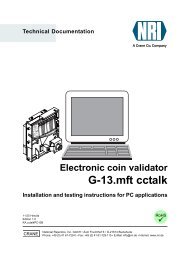
DESIGN<br />
G-13.mft MDB/S1<br />
Interfaces<br />
At the bottom right-hand side on the rear of the coin validator there is a<br />
10-pole connecting plug to the vending machine, and on the left-hand side<br />
at the centre there is a 3-pole JST plug for connecting an external sorting<br />
device. On the left-hand side, there is the interface to the PC programming<br />
station and the Palm handheld. (See Fig. 1a and 1b)<br />
Interface – vending machine<br />
The coin validator is connected to the machine via the serial MDB interface 8<br />
(see Fig. 1a and 1b) and a 10-pole cable via which it can receive information<br />
from the vending machine or send information to the vending machine. The<br />
machine operates as a master and the G-13.mft as a slave. The master can<br />
communicate with several slaves (e.g. coin and bill validator). To ensure<br />
unambiguous communication each device has its own MDB address. The<br />
address of the G-13.mft as an MDB model is "01", and "15" as an S1 model.<br />
The G-13.mft as an MDB model does not fulfil the MDB specification<br />
on two counts, i.e. the specified voltage range and the electrical<br />
isolation of the communication lines.<br />
If a supply voltage of 42 V max. and electrical isolation are<br />
desirable, an MDB converter G-55.0360 can be ordered from NRI<br />
(ordering code 23627).<br />
You can obtain further information about the MDB and S1 interface:<br />
• in the "NAMA document MDB/ICP 2.0" (www.vending.org) and<br />
• in the NRI S1 specification for the G-40 S1, which will be placed at<br />
your disposal upon your request.<br />
You will find a list of the commands implemented in the G-13.mft in<br />
Chap. 9 "Technical data".<br />
Please refer to the section "Pin assignment and connection<br />
diagrams" also included in Chap. 9 "Technical data" for more details<br />
on the assignment of individual plugs (pins).<br />
16 <strong>National</strong> <strong>Rejectors</strong>, <strong>Inc</strong>. <strong>GmbH</strong>, Buxtehude