

Parts Sheet - You are now at the Down-Load Site for Tol-O - Tolomatic
Parts Sheet - You are now at the Down-Load Site for Tol-O - Tolomatic
Parts Sheet - You are now at the Down-Load Site for Tol-O - Tolomatic

Create successful ePaper yourself
Turn your PDF publications into a flip-book with our unique Google optimized e-Paper software.
2 – Profiled Rail Belt-Drive Actu<strong>at</strong>ors MXB16P <strong>Parts</strong> <strong>Sheet</strong> #8500-4002_00<br />
PROCEDURE - MXB16P<br />
14<br />
15<br />
16<br />
17<br />
18<br />
19<br />
11<br />
12<br />
13<br />
6<br />
5<br />
4<br />
3<br />
20 21 22<br />
1<br />
2<br />
7<br />
8<br />
9<br />
10<br />
23<br />
24<br />
25<br />
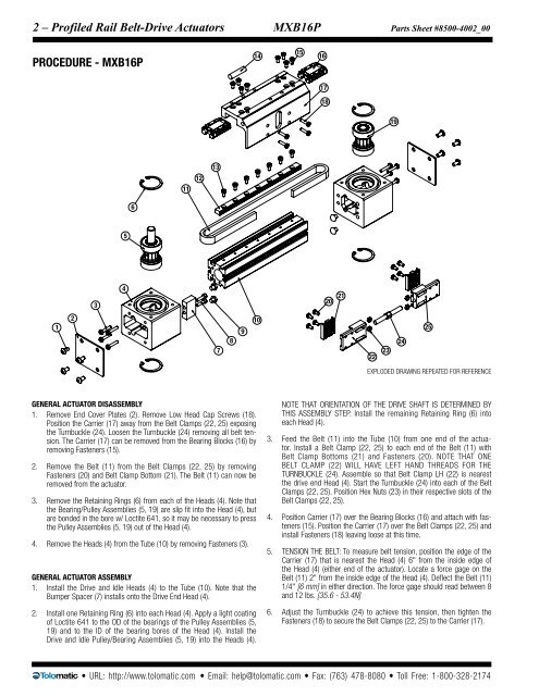
EXPLODED DRAWING REPEATED FOR REFERENCE<br />
General Actu<strong>at</strong>or Disassembly<br />
1. Remove End Cover Pl<strong>at</strong>es (2). Remove Low Head Cap Screws (18).<br />
Position <strong>the</strong> Carrier (17) away from <strong>the</strong> Belt Clamps (22, 25) exposing<br />
<strong>the</strong> Turnbuckle (24). Loosen <strong>the</strong> Turnbuckle (24) removing all belt tension.<br />
The Carrier (17) can be removed from <strong>the</strong> Bearing Blocks (16) by<br />
removing Fasteners (15).<br />
2. Remove <strong>the</strong> Belt (11) from <strong>the</strong> Belt Clamps (22, 25) by removing<br />
Fasteners (20) and Belt Clamp Bottom (21). The Belt (11) can <strong>now</strong> be<br />
removed from <strong>the</strong> actu<strong>at</strong>or.<br />
3. Remove <strong>the</strong> Retaining Rings (6) from each of <strong>the</strong> Heads (4). Note th<strong>at</strong><br />
<strong>the</strong> Bearing/Pulley Assemblies (5, 19) <strong>are</strong> slip fit into <strong>the</strong> Head (4), but<br />
<strong>are</strong> bonded in <strong>the</strong> bore w/ Loctite 641, so it may be necessary to press<br />
<strong>the</strong> Pulley Assemblies (5, 19) out of <strong>the</strong> Head (4).<br />
4. Remove <strong>the</strong> Heads (4) from <strong>the</strong> Tube (10) by removing Fasteners (3).<br />
General Actu<strong>at</strong>or Assembly<br />
1. Install <strong>the</strong> Drive and Idle Heads (4) to <strong>the</strong> Tube (10). Note th<strong>at</strong> <strong>the</strong><br />
Bumper Spacer (7) installs onto <strong>the</strong> Drive End Head (4).<br />
2. Install one Retaining Ring (6) into each Head (4). Apply a light co<strong>at</strong>ing<br />
of Loctite 641 to <strong>the</strong> OD of <strong>the</strong> bearings of <strong>the</strong> Pulley Assemblies (5,<br />
19) and to <strong>the</strong> ID of <strong>the</strong> bearing bores of <strong>the</strong> Head (4). Install <strong>the</strong><br />
Drive and Idle Pulley/Bearing Assemblies (5, 19) into <strong>the</strong> Heads (4).<br />
Note th<strong>at</strong> orient<strong>at</strong>ion of <strong>the</strong> drive shaft is determined by<br />
this assembly step. Install <strong>the</strong> remaining Retaining Ring (6) into<br />
each Head (4).<br />
3. Feed <strong>the</strong> Belt (11) into <strong>the</strong> Tube (10) from one end of <strong>the</strong> actu<strong>at</strong>or.<br />
Install a Belt Clamp (22, 25) to each end of <strong>the</strong> Belt (11) with<br />
Belt Clamp Bottoms (21) and Fasteners (20). Note th<strong>at</strong> one<br />
Belt Clamp (22) will have left hand threads <strong>for</strong> <strong>the</strong><br />
Turnbuckle (24). Assemble so th<strong>at</strong> Belt Clamp LH (22) is ne<strong>are</strong>st<br />
<strong>the</strong> drive end Head (4). Start <strong>the</strong> Turnbuckle (24) into each of <strong>the</strong> Belt<br />
Clamps (22, 25). Position Hex Nuts (23) in <strong>the</strong>ir respective slots of <strong>the</strong><br />
Belt Clamps (22, 25).<br />
4. Position Carrier (17) over <strong>the</strong> Bearing Blocks (16) and <strong>at</strong>tach with fasteners<br />
(15). Position <strong>the</strong> Carrier (17) over <strong>the</strong> Belt Clamps (22, 25) and<br />
install Fasteners (18) leaving loose <strong>at</strong> this time.<br />
5. Tension <strong>the</strong> Belt: To measure belt tension, position <strong>the</strong> edge of <strong>the</strong><br />
Carrier (17) th<strong>at</strong> is ne<strong>are</strong>st <strong>the</strong> Head (4) 6" from <strong>the</strong> inside edge of<br />
<strong>the</strong> Head (4) (ei<strong>the</strong>r end of <strong>the</strong> actu<strong>at</strong>or). Loc<strong>at</strong>e a <strong>for</strong>ce gage on <strong>the</strong><br />
Belt (11) 2" from <strong>the</strong> inside edge of <strong>the</strong> Head (4). Deflect <strong>the</strong> Belt (11)<br />
1/4" [6 mm] in ei<strong>the</strong>r direction. The <strong>for</strong>ce gage should read between 8<br />
and 12 lbs. [35.6 - 53.4N]<br />
6. Adjust <strong>the</strong> Turnbuckle (24) to achieve this tension, <strong>the</strong>n tighten <strong>the</strong><br />
Fasteners (18) to secure <strong>the</strong> Belt Clamps (22, 25) to <strong>the</strong> Carrier (17).<br />
• URL: http://www.tolom<strong>at</strong>ic.com • Email: help@tolom<strong>at</strong>ic.com • Fax: (763) 478-8080 • <strong>Tol</strong>l Free: 1-800-328-2174


