

Parts Sheet - You are now at the Down-Load Site for Tol-O - Tolomatic
Parts Sheet - You are now at the Down-Load Site for Tol-O - Tolomatic
Parts Sheet - You are now at the Down-Load Site for Tol-O - Tolomatic

Create successful ePaper yourself
Turn your PDF publications into a flip-book with our unique Google optimized e-Paper software.
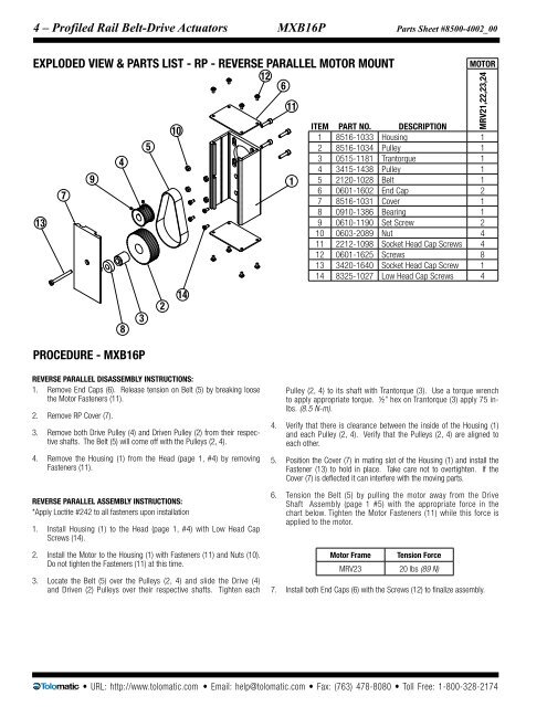
4 – Profiled Rail Belt-Drive Actu<strong>at</strong>ors MXB16P <strong>Parts</strong> <strong>Sheet</strong> #8500-4002_00<br />
EXPLODED VIEW & PARTS LIST - RP - REVERSE PARALLEL MOTOR MOUNT<br />
12<br />
6<br />
13<br />
7<br />
PROCEDURE - MXB16P<br />
9<br />
4<br />
8<br />
3<br />
5<br />
2<br />
10<br />
14<br />
11<br />
1<br />
MOTOR<br />
MRV21,22,23,24<br />
ITEM PART NO. DESCRIPTION<br />
1 8516-1033 Housing 1<br />
2 8516-1034 Pulley 1<br />
3 0515-1181 Trantorque 1<br />
4 3415-1438 Pulley 1<br />
5 2120-1028 Belt 1<br />
6 0601-1602 End Cap 2<br />
7 8516-1031 Cover 1<br />
8 0910-1386 Bearing 1<br />
9 0610-1190 Set Screw 2<br />
10 0603-2089 Nut 4<br />
11 2212-1098 Socket Head Cap Screws 4<br />
12 0601-1625 Screws 8<br />
13 3420-1640 Socket Head Cap Screw 1<br />
14 8325-1027 Low Head Cap Screws 4<br />
Reverse Parallel Disassembly Instructions:<br />
1. Remove End Caps (6). Release tension on Belt (5) by breaking loose<br />
<strong>the</strong> Motor Fasteners (11).<br />
2. Remove RP Cover (7).<br />
3. Remove both Drive Pulley (4) and Driven Pulley (2) from <strong>the</strong>ir respective<br />
shafts. The Belt (5) will come off with <strong>the</strong> Pulleys (2, 4).<br />
4. Remove <strong>the</strong> Housing (1) from <strong>the</strong> Head (page 1, #4) by removing<br />
Fasteners (11).<br />
Reverse Parallel assembly Instructions:<br />
*Apply Loctite #242 to all fasteners upon install<strong>at</strong>ion<br />
1. Install Housing (1) to <strong>the</strong> Head (page 1, #4) with Low Head Cap<br />
Screws (14).<br />
2. Install <strong>the</strong> Motor to <strong>the</strong> Housing (1) with Fasteners (11) and Nuts (10).<br />
Do not tighten <strong>the</strong> Fasteners (11) <strong>at</strong> this time.<br />
3. Loc<strong>at</strong>e <strong>the</strong> Belt (5) over <strong>the</strong> Pulleys (2, 4) and slide <strong>the</strong> Drive (4)<br />
and Driven (2) Pulleys over <strong>the</strong>ir respective shafts. Tighten each<br />
Pulley (2, 4) to its shaft with Trantorque (3). Use a torque wrench<br />
to apply appropri<strong>at</strong>e torque. ½” hex on Trantorque (3) apply 75 inlbs.<br />
(8.5 N-m).<br />
4. Verify th<strong>at</strong> <strong>the</strong>re is clearance between <strong>the</strong> inside of <strong>the</strong> Housing (1)<br />
and each Pulley (2, 4). Verify th<strong>at</strong> <strong>the</strong> Pulleys (2, 4) <strong>are</strong> aligned to<br />
each o<strong>the</strong>r.<br />
5. Position <strong>the</strong> Cover (7) in m<strong>at</strong>ing slot of <strong>the</strong> Housing (1) and install <strong>the</strong><br />
Fastener (13) to hold in place. Take c<strong>are</strong> not to overtighten. If <strong>the</strong><br />
Cover (7) is deflected it can interfere with <strong>the</strong> moving parts.<br />
6. Tension <strong>the</strong> Belt (5) by pulling <strong>the</strong> motor away from <strong>the</strong> Drive<br />
Shaft Assembly (page 1 #5) with <strong>the</strong> appropri<strong>at</strong>e <strong>for</strong>ce in <strong>the</strong><br />
chart below. Tighten <strong>the</strong> Motor Fasteners (11) while this <strong>for</strong>ce is<br />
applied to <strong>the</strong> motor.<br />
Motor Frame<br />
Tension Force<br />
MRV23 20 lbs (89 N)<br />
7. Install both End Caps (6) with <strong>the</strong> Screws (12) to finalize assembly.<br />
• URL: http://www.tolom<strong>at</strong>ic.com • Email: help@tolom<strong>at</strong>ic.com • Fax: (763) 478-8080 • <strong>Tol</strong>l Free: 1-800-328-2174


