

Parts Sheet - You are now at the Down-Load Site for Tol-O - Tolomatic
Parts Sheet - You are now at the Down-Load Site for Tol-O - Tolomatic
Parts Sheet - You are now at the Down-Load Site for Tol-O - Tolomatic

You also want an ePaper? Increase the reach of your titles
YUMPU automatically turns print PDFs into web optimized ePapers that Google loves.
<strong>Parts</strong> <strong>Sheet</strong> #8500-4002_00 MXB16P Profiled Rail Belt-Drive Actu<strong>at</strong>ors – 1<br />
<strong>Parts</strong> <strong>Sheet</strong><br />
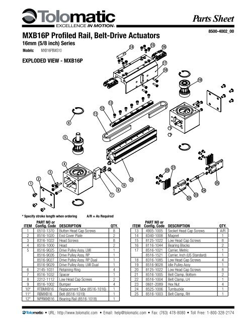
MXB16P Profiled Rail, Belt-Drive Actu<strong>at</strong>ors<br />
16mm (5/8 inch) Series<br />
Models: MXB16PBWS10<br />
EXPLODED VIEW - MXB16P<br />
15<br />
14<br />
16<br />
17<br />
18<br />
8500-4002_00<br />
19<br />
11<br />
12<br />
13<br />
6<br />
5<br />
4<br />
3<br />
20 21 22<br />
1<br />
2<br />
7<br />
8<br />
9<br />
10<br />
23<br />
24<br />
25<br />
* Specify stroke length when ordering A/R = As Required<br />
ITEM<br />
PART NO or<br />
Config. Code DESCRIPTION QTY.<br />
1 0510-1370 Button Head Cap Screws 8<br />
2 8516-1020 End Cover Pl<strong>at</strong>e 2<br />
3 8316-1022 Head Screws 8<br />
4 8516-1000 Head 2<br />
5 8516-9025 Drive Pulley Assy. LMI 1<br />
8516-9026 Drive Pulley Assy. RP 1<br />
8516-9027 Drive Pulley Assy. RP Dual 1<br />
8516-9029 Drive Pulley Assy. LMI Dual 1<br />
6 2145-1031 Retaining Ring 4<br />
7 8516-1032 Spacer 1<br />
8 2212-1112 Low Head Cap Screws 2<br />
9 8516-1002 Bumper 4<br />
10* RTBMXB16 Replacement Tube (8516-1016) 1<br />
11* RBMXB16 Belt (8516-1019) 1<br />
12* NPRMXB16 Bearing Rail (8516-1018) 1<br />
ITEM<br />
PART NO or<br />
Config. Code DESCRIPTION QTY.<br />
13 4905-1005 Socket Head Cap Screws A/R<br />
14 8340-1008 Magnet 1<br />
15 8125-1022 Low Head Cap Screws 8<br />
16 8116-1044 Bearing Blocks 2<br />
17 8516-1021 Carrier, Metric 1<br />
8516-1521 Carrier, Inch (US Standard) 1<br />
18 8316-1085 Low Head Cap Screws 4<br />
19 8516-9028 Idle Pulley Assy 1<br />
20 8125-1022 Low Head Cap Screws 8<br />
21 8516-1005 Belt Clamp, Bottom 2<br />
22 8516-1004 Belt Clamp, LH 1<br />
23 0601-2089 Hex Nut 4<br />
24 8525-1006 Turnbuckle 1<br />
25 8516-1003 Belt Clamp, RH 1<br />
• URL: http://www.tolom<strong>at</strong>ic.com • Email: help@tolom<strong>at</strong>ic.com • Fax: (763) 478-8080 • <strong>Tol</strong>l Free: 1-800-328-2174
2 – Profiled Rail Belt-Drive Actu<strong>at</strong>ors MXB16P <strong>Parts</strong> <strong>Sheet</strong> #8500-4002_00<br />
PROCEDURE - MXB16P<br />
14<br />
15<br />
16<br />
17<br />
18<br />
19<br />
11<br />
12<br />
13<br />
6<br />
5<br />
4<br />
3<br />
20 21 22<br />
1<br />
2<br />
7<br />
8<br />
9<br />
10<br />
23<br />
24<br />
25<br />
EXPLODED DRAWING REPEATED FOR REFERENCE<br />
General Actu<strong>at</strong>or Disassembly<br />
1. Remove End Cover Pl<strong>at</strong>es (2). Remove Low Head Cap Screws (18).<br />
Position <strong>the</strong> Carrier (17) away from <strong>the</strong> Belt Clamps (22, 25) exposing<br />
<strong>the</strong> Turnbuckle (24). Loosen <strong>the</strong> Turnbuckle (24) removing all belt tension.<br />
The Carrier (17) can be removed from <strong>the</strong> Bearing Blocks (16) by<br />
removing Fasteners (15).<br />
2. Remove <strong>the</strong> Belt (11) from <strong>the</strong> Belt Clamps (22, 25) by removing<br />
Fasteners (20) and Belt Clamp Bottom (21). The Belt (11) can <strong>now</strong> be<br />
removed from <strong>the</strong> actu<strong>at</strong>or.<br />
3. Remove <strong>the</strong> Retaining Rings (6) from each of <strong>the</strong> Heads (4). Note th<strong>at</strong><br />
<strong>the</strong> Bearing/Pulley Assemblies (5, 19) <strong>are</strong> slip fit into <strong>the</strong> Head (4), but<br />
<strong>are</strong> bonded in <strong>the</strong> bore w/ Loctite 641, so it may be necessary to press<br />
<strong>the</strong> Pulley Assemblies (5, 19) out of <strong>the</strong> Head (4).<br />
4. Remove <strong>the</strong> Heads (4) from <strong>the</strong> Tube (10) by removing Fasteners (3).<br />
General Actu<strong>at</strong>or Assembly<br />
1. Install <strong>the</strong> Drive and Idle Heads (4) to <strong>the</strong> Tube (10). Note th<strong>at</strong> <strong>the</strong><br />
Bumper Spacer (7) installs onto <strong>the</strong> Drive End Head (4).<br />
2. Install one Retaining Ring (6) into each Head (4). Apply a light co<strong>at</strong>ing<br />
of Loctite 641 to <strong>the</strong> OD of <strong>the</strong> bearings of <strong>the</strong> Pulley Assemblies (5,<br />
19) and to <strong>the</strong> ID of <strong>the</strong> bearing bores of <strong>the</strong> Head (4). Install <strong>the</strong><br />
Drive and Idle Pulley/Bearing Assemblies (5, 19) into <strong>the</strong> Heads (4).<br />
Note th<strong>at</strong> orient<strong>at</strong>ion of <strong>the</strong> drive shaft is determined by<br />
this assembly step. Install <strong>the</strong> remaining Retaining Ring (6) into<br />
each Head (4).<br />
3. Feed <strong>the</strong> Belt (11) into <strong>the</strong> Tube (10) from one end of <strong>the</strong> actu<strong>at</strong>or.<br />
Install a Belt Clamp (22, 25) to each end of <strong>the</strong> Belt (11) with<br />
Belt Clamp Bottoms (21) and Fasteners (20). Note th<strong>at</strong> one<br />
Belt Clamp (22) will have left hand threads <strong>for</strong> <strong>the</strong><br />
Turnbuckle (24). Assemble so th<strong>at</strong> Belt Clamp LH (22) is ne<strong>are</strong>st<br />
<strong>the</strong> drive end Head (4). Start <strong>the</strong> Turnbuckle (24) into each of <strong>the</strong> Belt<br />
Clamps (22, 25). Position Hex Nuts (23) in <strong>the</strong>ir respective slots of <strong>the</strong><br />
Belt Clamps (22, 25).<br />
4. Position Carrier (17) over <strong>the</strong> Bearing Blocks (16) and <strong>at</strong>tach with fasteners<br />
(15). Position <strong>the</strong> Carrier (17) over <strong>the</strong> Belt Clamps (22, 25) and<br />
install Fasteners (18) leaving loose <strong>at</strong> this time.<br />
5. Tension <strong>the</strong> Belt: To measure belt tension, position <strong>the</strong> edge of <strong>the</strong><br />
Carrier (17) th<strong>at</strong> is ne<strong>are</strong>st <strong>the</strong> Head (4) 6" from <strong>the</strong> inside edge of<br />
<strong>the</strong> Head (4) (ei<strong>the</strong>r end of <strong>the</strong> actu<strong>at</strong>or). Loc<strong>at</strong>e a <strong>for</strong>ce gage on <strong>the</strong><br />
Belt (11) 2" from <strong>the</strong> inside edge of <strong>the</strong> Head (4). Deflect <strong>the</strong> Belt (11)<br />
1/4" [6 mm] in ei<strong>the</strong>r direction. The <strong>for</strong>ce gage should read between 8<br />
and 12 lbs. [35.6 - 53.4N]<br />
6. Adjust <strong>the</strong> Turnbuckle (24) to achieve this tension, <strong>the</strong>n tighten <strong>the</strong><br />
Fasteners (18) to secure <strong>the</strong> Belt Clamps (22, 25) to <strong>the</strong> Carrier (17).<br />
• URL: http://www.tolom<strong>at</strong>ic.com • Email: help@tolom<strong>at</strong>ic.com • Fax: (763) 478-8080 • <strong>Tol</strong>l Free: 1-800-328-2174
<strong>Parts</strong> <strong>Sheet</strong> #8500-4002_00 MXB16P Profiled Rail Belt-Drive Actu<strong>at</strong>ors – 3<br />
EXPLODED VIEW & PARTS LIST - LMI - INLINE MOTOR MOUNT<br />
3<br />
2<br />
1<br />
5<br />
6<br />
4<br />
MOTOR<br />
MOTOR<br />
& GH<br />
MRV21,22,23,24<br />
MRV21,22,23,24<br />
& GHV205,210<br />
ITEM PART NO. DESCRIPTION<br />
8516-1035 Motor Spacer 1<br />
1<br />
8516-1038 Motor Spacer 1<br />
2 1112-1032 Cover 1 1<br />
3 1124-1159 Socket Head Cap Screw 1 1<br />
4 0602-1027 Socket Head Cap Screw 4 4<br />
0602-1029 Socket Head Cap Screw 4<br />
5<br />
0604-1028 Socket Head Cap Screw 4<br />
6 3600-9253 Coupler 1 1<br />
• URL: http://www.tolom<strong>at</strong>ic.com • Email: help@tolom<strong>at</strong>ic.com • Fax: (763) 478-8080 • <strong>Tol</strong>l Free: 1-800-328-2174
4 – Profiled Rail Belt-Drive Actu<strong>at</strong>ors MXB16P <strong>Parts</strong> <strong>Sheet</strong> #8500-4002_00<br />
EXPLODED VIEW & PARTS LIST - RP - REVERSE PARALLEL MOTOR MOUNT<br />
12<br />
6<br />
13<br />
7<br />
PROCEDURE - MXB16P<br />
9<br />
4<br />
8<br />
3<br />
5<br />
2<br />
10<br />
14<br />
11<br />
1<br />
MOTOR<br />
MRV21,22,23,24<br />
ITEM PART NO. DESCRIPTION<br />
1 8516-1033 Housing 1<br />
2 8516-1034 Pulley 1<br />
3 0515-1181 Trantorque 1<br />
4 3415-1438 Pulley 1<br />
5 2120-1028 Belt 1<br />
6 0601-1602 End Cap 2<br />
7 8516-1031 Cover 1<br />
8 0910-1386 Bearing 1<br />
9 0610-1190 Set Screw 2<br />
10 0603-2089 Nut 4<br />
11 2212-1098 Socket Head Cap Screws 4<br />
12 0601-1625 Screws 8<br />
13 3420-1640 Socket Head Cap Screw 1<br />
14 8325-1027 Low Head Cap Screws 4<br />
Reverse Parallel Disassembly Instructions:<br />
1. Remove End Caps (6). Release tension on Belt (5) by breaking loose<br />
<strong>the</strong> Motor Fasteners (11).<br />
2. Remove RP Cover (7).<br />
3. Remove both Drive Pulley (4) and Driven Pulley (2) from <strong>the</strong>ir respective<br />
shafts. The Belt (5) will come off with <strong>the</strong> Pulleys (2, 4).<br />
4. Remove <strong>the</strong> Housing (1) from <strong>the</strong> Head (page 1, #4) by removing<br />
Fasteners (11).<br />
Reverse Parallel assembly Instructions:<br />
*Apply Loctite #242 to all fasteners upon install<strong>at</strong>ion<br />
1. Install Housing (1) to <strong>the</strong> Head (page 1, #4) with Low Head Cap<br />
Screws (14).<br />
2. Install <strong>the</strong> Motor to <strong>the</strong> Housing (1) with Fasteners (11) and Nuts (10).<br />
Do not tighten <strong>the</strong> Fasteners (11) <strong>at</strong> this time.<br />
3. Loc<strong>at</strong>e <strong>the</strong> Belt (5) over <strong>the</strong> Pulleys (2, 4) and slide <strong>the</strong> Drive (4)<br />
and Driven (2) Pulleys over <strong>the</strong>ir respective shafts. Tighten each<br />
Pulley (2, 4) to its shaft with Trantorque (3). Use a torque wrench<br />
to apply appropri<strong>at</strong>e torque. ½” hex on Trantorque (3) apply 75 inlbs.<br />
(8.5 N-m).<br />
4. Verify th<strong>at</strong> <strong>the</strong>re is clearance between <strong>the</strong> inside of <strong>the</strong> Housing (1)<br />
and each Pulley (2, 4). Verify th<strong>at</strong> <strong>the</strong> Pulleys (2, 4) <strong>are</strong> aligned to<br />
each o<strong>the</strong>r.<br />
5. Position <strong>the</strong> Cover (7) in m<strong>at</strong>ing slot of <strong>the</strong> Housing (1) and install <strong>the</strong><br />
Fastener (13) to hold in place. Take c<strong>are</strong> not to overtighten. If <strong>the</strong><br />
Cover (7) is deflected it can interfere with <strong>the</strong> moving parts.<br />
6. Tension <strong>the</strong> Belt (5) by pulling <strong>the</strong> motor away from <strong>the</strong> Drive<br />
Shaft Assembly (page 1 #5) with <strong>the</strong> appropri<strong>at</strong>e <strong>for</strong>ce in <strong>the</strong><br />
chart below. Tighten <strong>the</strong> Motor Fasteners (11) while this <strong>for</strong>ce is<br />
applied to <strong>the</strong> motor.<br />
Motor Frame<br />
Tension Force<br />
MRV23 20 lbs (89 N)<br />
7. Install both End Caps (6) with <strong>the</strong> Screws (12) to finalize assembly.<br />
• URL: http://www.tolom<strong>at</strong>ic.com • Email: help@tolom<strong>at</strong>ic.com • Fax: (763) 478-8080 • <strong>Tol</strong>l Free: 1-800-328-2174
<strong>Parts</strong> <strong>Sheet</strong> #8500-4002_00 MXB16P Profiled Rail Belt-Drive Actu<strong>at</strong>ors – 5<br />
EXPLODED VIEW & PARTS LIST - OPTIONS<br />
4<br />
5<br />
2<br />
3<br />
6<br />
1<br />
ITEM PART NO. DESCRIPTION<br />
1<br />
8516-9014 Dual Carrier Assembly, metric<br />
8516-9514 Dual Carrier Assembly, inch (US Standard)<br />
SWITCHES WITH QUICK-DISCONNECT COUPLERS<br />
8100-9083 RK Reed Switch, SPST Normally Open<br />
8100-9085 NK Reed Switch, SPST Normally Closed<br />
2<br />
8100-9089 TK Solid St<strong>at</strong>e Switch, PNP (Sourcing) Normally Open<br />
8100-9091 KK Solid St<strong>at</strong>e Switch, NPN (Sinking) Normally Open<br />
8100-9093 PK Solid St<strong>at</strong>e Switch, PNP (Sourcing) Normally Closed<br />
8100-9095 HK Solid St<strong>at</strong>e Switch, NPN (Sinking) Normally Closed<br />
3 8100-9080 Female Connector For QuicK Disconnect, 5 Meter<br />
SWITCHES WITHOUT QUICK-DISCONNECT COUPLERS<br />
8100-9082 RY Reed Switch, SPST Normally Open<br />
8100-9084 NY Reed Switch, MXB16 SPST OPTIONS Normally Closed 2/9/09<br />
4<br />
8100-9088 TY Solid St<strong>at</strong>e Switch, PNP (Sourcing) Normally Open<br />
8100-9090 KY Solid St<strong>at</strong>e Switch, NPN (Sinking) Normally Open<br />
8100-9092 PY Solid St<strong>at</strong>e Switch, PNP (Sourcing) Normally Closed<br />
8100-9094 HY Solid St<strong>at</strong>e Switch, NPN (Sinking) Normally Closed<br />
5 8516-9008 Side Cover Pl<strong>at</strong>e Assembly<br />
8516-1029 Cover Pl<strong>at</strong>e<br />
0510-1370 Button Head Cap Screw<br />
6 8516-9030 Mounting Pl<strong>at</strong>e Kit<br />
8516-1070 Mounting Pl<strong>at</strong>e<br />
8316-1050 T-Nut<br />
0604-1028 Socket Head Cap Screw<br />
• URL: http://www.tolom<strong>at</strong>ic.com • Email: help@tolom<strong>at</strong>ic.com • Fax: (763) 478-8080 • <strong>Tol</strong>l Free: 1-800-328-2174
<strong>Parts</strong> <strong>Sheet</strong> #8500-4002_00 MXB16P Switch Diagrams – 6<br />
SWITCH WIRING DIAGRAMS AND LABEL COLOR CODING (CE and RoHS Compliant)<br />
RY, #8100-9082, • RK, #8100-9083<br />
REED • NORMALLY OPEN<br />
BRN<br />
NORMALLY<br />
OPEN BLU<br />
LOAD<br />
or<br />
NORMALLY<br />
OPEN<br />
BRN<br />
BLU<br />
LOAD<br />
+<br />
-<br />
+<br />
-<br />
TY, #8100-9088, • TK, #8100-9089<br />
SOLID STATE • NORMALLY OPEN • PNP<br />
BRN<br />
NORMALLY<br />
OPEN PNP<br />
(SOURCING)<br />
BLK<br />
BLU<br />
+<br />
SIGNAL<br />
LOAD<br />
-<br />
KY, #8100-9090, • KK, #8100-9091<br />
SOLID STATE • NORMALLY OPEN • NPN<br />
NORMALLY<br />
OPEN NPN<br />
(SINKING)<br />
BRN<br />
BLK<br />
BLU<br />
+<br />
LOAD<br />
SIGNAL<br />
-<br />
NY, #8100-9084, • NK, #8100-9085<br />
REED • NORMALLY CLOSED<br />
BRN<br />
NORMALLY<br />
CLOSED BLU<br />
LOAD<br />
or<br />
NORMALLY<br />
CLOSED<br />
BRN<br />
BLU<br />
LOAD<br />
+<br />
-<br />
+<br />
-<br />
PY, #8100-9092, • PK, #8100-9093<br />
SOLID STATE • NORMALLY CLOSED • PNP<br />
NORMALLY<br />
CLOSED PNP<br />
(SOURCING)<br />
BRN<br />
BLK<br />
BLU<br />
+<br />
SIGNAL<br />
LOAD<br />
-<br />
HY, #8100-9094, • HK, #8100-9095<br />
SOLID STATE • NORMALLY CLOSED • NPN<br />
BRN<br />
NORMALLY<br />
CLOSED NPN<br />
(SINKING)<br />
BLK<br />
BLU<br />
+<br />
LOAD<br />
SIGNAL<br />
-<br />
QUICK DISCONNECT MALE PLUG PINOUT<br />
BLACK<br />
(SIGNAL)<br />
BLUE (-)<br />
BROWN (+)<br />
#8100-9080 QUICK DISCONNECT<br />
FEMALE SOCKET PINOUT<br />
BLACK<br />
(SIGNAL)<br />
BROWN (+)<br />
BLUE (-)<br />
Switch install<strong>at</strong>ion and replacement<br />
Insert<br />
switch<br />
<strong>Tol</strong>om<strong>at</strong>ic<br />
Rot<strong>at</strong>e<br />
switch<br />
<strong>Tol</strong>om<strong>at</strong>ic<br />
Secure<br />
switch<br />
<strong>Tol</strong>om<strong>at</strong>ic<br />
Place switch in side groove on tube <strong>at</strong> desired loc<strong>at</strong>ion with "<strong>Tol</strong>om<strong>at</strong>ic" facing<br />
outward. While applying light pressure to <strong>the</strong> switch, rot<strong>at</strong>e <strong>the</strong> switch halfway into<br />
<strong>the</strong> groove. Maintaining light pressure, rot<strong>at</strong>e <strong>the</strong> switch in <strong>the</strong> opposite direction<br />
until <strong>the</strong> switch is fully inside <strong>the</strong> groove with "<strong>Tol</strong>om<strong>at</strong>ic" visible. Re-position <strong>the</strong><br />
switch to <strong>the</strong> exact loc<strong>at</strong>ion and lock it securely into place by tightening <strong>the</strong> screw<br />
on <strong>the</strong> switch.<br />
SWITCH DIMENSIONS<br />
_ Y - direct connect<br />
Switch Detection point<br />
DETECTION POINT<br />
SOLID STATE<br />
.31 [8]<br />
.51 [13]<br />
197 [5000]<br />
Dimensions in inches [brackets indic<strong>at</strong>e dimensions in millimeters]<br />
1.18 [30]<br />
DETECTION POINT REED<br />
_ K - QD (Quick disconnect) switch<br />
M8x1<br />
MOUNTING DIMENSIONS<br />
16, 25, 32<br />
SWITCHES SIT BELOW<br />
TUBE EXTRUSION PROFILE<br />
V<br />
U<br />
40, 50, 63<br />
SWITCHES SIT BELOW<br />
TUBE EXTRUSION PROFILE<br />
V<br />
W<br />
U<br />
X<br />
13.35 [339]<br />
M8x1<br />
Ø.35<br />
[9]<br />
8100-9180 - QD Cable<br />
1.26 [32.1]<br />
.95 [24.1]<br />
3800 County Road 116, Hamel, MN 55340<br />
Ø.28 [7]<br />
http://www.<strong>Tol</strong>om<strong>at</strong>ic.com • Email:<br />
197<br />
Help@<strong>Tol</strong>om<strong>at</strong>ic.com<br />
[5000]<br />
Phone: (763) 478-8000 • Fax: (763) 478-8080 • <strong>Tol</strong>l Free: 1-800-328-2174<br />
© 2009 <strong>Tol</strong>om<strong>at</strong>ic 200904231335<br />
In<strong>for</strong>m<strong>at</strong>ion furnished is believed to be accur<strong>at</strong>e<br />
and reliable. However, <strong>Tol</strong>om<strong>at</strong>ic assumes no<br />
responsibility <strong>for</strong> its use or <strong>for</strong> any errors th<strong>at</strong><br />
may appear in this document. <strong>Tol</strong>om<strong>at</strong>ic reserves<br />
<strong>the</strong> right to change <strong>the</strong> design or oper<strong>at</strong>ion of <strong>the</strong><br />
equipment described herein and any associ<strong>at</strong>ed<br />
motion products without notice. In<strong>for</strong>m<strong>at</strong>ion in<br />
this document is subject to change without notice.


