

Parts Sheet - You are now at the Down-Load Site for Tol-O - Tolomatic
Parts Sheet - You are now at the Down-Load Site for Tol-O - Tolomatic
Parts Sheet - You are now at the Down-Load Site for Tol-O - Tolomatic

Create successful ePaper yourself
Turn your PDF publications into a flip-book with our unique Google optimized e-Paper software.
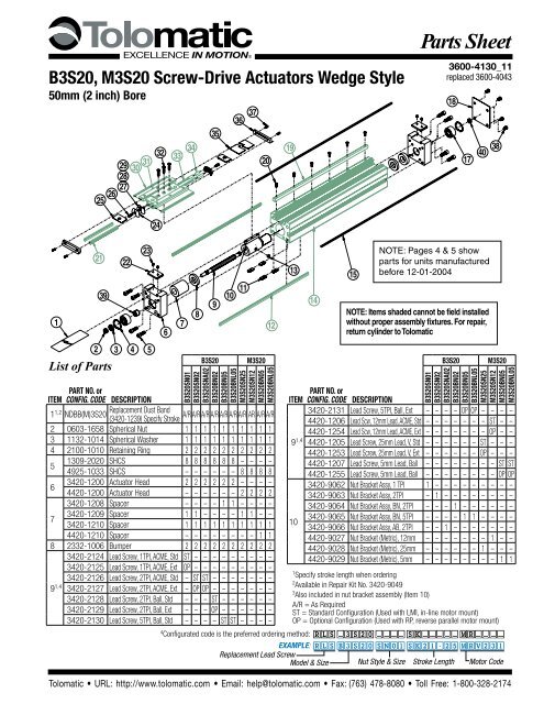
B3S20, M3S20 Screw-Drive Actu<strong>at</strong>ors Wedge Style<br />
50mm (2 inch) Bore<br />
1<br />
29<br />
28<br />
27<br />
26<br />
25<br />
21<br />
2<br />
39<br />
List of <strong>Parts</strong><br />
22<br />
31<br />
30<br />
23<br />
3 4 5<br />
24<br />
32<br />
6<br />
33<br />
7<br />
34<br />
8<br />
35<br />
9<br />
B3S20<br />
36<br />
37<br />
<strong>Parts</strong> <strong>Sheet</strong><br />
3600-4130_11_B3S20<br />
replaced 3600-4043<br />
19<br />
38<br />
20<br />
17 40<br />
NOTE: Pages 4 & 5 show<br />
parts <strong>for</strong> units manufactured<br />
13<br />
15 be<strong>for</strong>e 12-01-2004<br />
10 11 14<br />
NOTE: Items shaded cannot be field installed<br />
12<br />
without proper assembly fixtures. For repair,<br />
return cylinder to <strong>Tol</strong>om<strong>at</strong>ic<br />
M3S20<br />
B3S20SN01<br />
B3S20SN02<br />
B3S20SNA02<br />
B3S20BN02<br />
B3S20BN05<br />
B3S20BNL05<br />
M3S20SN25<br />
M3S20SN12<br />
M3S20BN05<br />
M3S20BNL05<br />
PART NO. or<br />
ITEM config. code DESCRIPTION<br />
1 1,2 NDBB(M)3S20<br />
Replacement Dust Band<br />
(3420-1239) Specify Stroke<br />
A/R A/R A/R A/R A/R A/R A/R AR A/R A/R<br />
2 0603-1658 Spherical Nut 1 1 1 1 1 1 1 1 1 1<br />
3 1132-1014 Spherical Washer 1 1 1 1 1 1 1 1 1 1<br />
4 2100-1010 Retaining Ring 2 2 2 2 2 2 2 2 2 2<br />
5<br />
1309-2020 SHCS 8 8 8 8 8 8 – – – –<br />
4925-1033 SHCS – – – – – – 8 8 8 8<br />
6<br />
3420-1200 Actu<strong>at</strong>or Head 2 2 2 2 2 2 – – – –<br />
4420-1200 Actu<strong>at</strong>or Head – – – – – – 2 2 2 2<br />
3420-1208 Spacer – – – – 1 1 – – – –<br />
7<br />
3420-1209 Spacer 1 1 – – – – 1 1 – –<br />
3420-1210 Spacer 1 1 1 1 1 1 1 1 1 1<br />
4420-1210 Spacer – – – – – – – – 1 1<br />
8 2332-1006 Bumper 2 2 2 2 2 2 2 2 2 2<br />
3420-2124 Lead Screw, 1TPI, ACME, Std ST – – – – – – – – –<br />
3420-2125 Lead Screw, 1TPI, ACME, Ext OP – – – – – – – – –<br />
3420-2126 Lead Screw, 2TPI, ACME, Std – ST ST – – – – – – –<br />
9 1,4 3420-2127 Lead Screw, 2TPI, ACME, Ext – OP OP – – – – – – –<br />
3420-2128 Lead Screw, 2TPI, Ball, Std – – – ST – – – – – –<br />
3420-2129 Lead Screw, 2TPI, Ball, Ext – – – OP – – – – – –<br />
3420-2130 Lead Screw, 5TPI, Ball, Std – – – – ST ST – – – –<br />
1<br />
Specify stroke length when ordering<br />
2<br />
Available in Repair Kit No. 3420-9049<br />
3<br />
Also included in nut bracket assembly (Item 10)<br />
A/R = As Required<br />
ST = Standard Configur<strong>at</strong>ion (Used with LMI, in-line motor mount)<br />
OP = Optional Configur<strong>at</strong>ion (Used with RP, reverse parallel motor mount)<br />
4<br />
Configur<strong>at</strong>ed code is <strong>the</strong> preferred ordering method: RLS _3S20 ____ SK_____ MR____<br />
Example: RLS B3S20 SN01 SK21.25 MRV231<br />
Replacement Lead Screw<br />
Model & Size Nut Style & Size Stroke Length Motor Code<br />
<strong>Tol</strong>om<strong>at</strong>ic • URL: http://www.tolom<strong>at</strong>ic.com • Email: help@tolom<strong>at</strong>ic.com • Fax: (763) 478-8080 • <strong>Tol</strong>l Free: 1-800-328-2174<br />
ITEM<br />
PART NO. or<br />
config. code DESCRIPTION<br />
18<br />
B3S20<br />
M3S20<br />
B3S20SN01<br />
B3S20SN02<br />
B3S20SNA02<br />
B3S20BN02<br />
B3S20BN05<br />
B3S20BNL05<br />
M3S20SN25<br />
M3S20SN12<br />
M3S20BN05<br />
M3S20BNL05<br />
9 1,4 4420-1205 Lead Screw, 25mm Lead, V, Std – – – – – – ST – – –<br />
3420-2131 Lead Screw, 5TPI, Ball, Ext – – – – OP OP – – – –<br />
4420-1206 Lead Scw, 12mm Lead, ACME, Std – – – – – – – ST – –<br />
4420-1254 Lead Scw, 12mm Lead, ACME, Ext – – – – – – – OP – –<br />
4420-1253 Lead Screw, 25mm Lead, V, Ext – – – – – – OP – – –<br />
4420-1207 Lead Screw, 5mm Lead, Ball – – – – – – – – ST ST<br />
4420-1255 Lead Screw, 5mm Lead, Ball – – – – – – – – OP OP<br />
10<br />
3420-9062 Nut Bracket Assy, 1 TPI 1 – – – – – – – – –<br />
3420-9063 Nut Bracket Assy, 2TPI – 1 – – – – – – – –<br />
3420-9064 Nut Bracket Assy, BN, 2TPI – – – 1 – – – – – –<br />
3420-9065 Nut Bracket Assy, BN, 5TPI – – – – 1 1 – – – –<br />
3420-9066 Nut Bracket Assy, AB, 2TPI – – 1 – – – – – – –<br />
4420-9027 Nut Bracket (Metric), 12mm – – – – – – – 1 – –<br />
4420-9028 Nut Bracket (Metric), 25mm – – – – – – 1 – – –<br />
4420-9029 Nut Bracket (Metric), 5mm – – – – – – – – 1 1
2 – Instructions B3S20, M3S20 <strong>Parts</strong> <strong>Sheet</strong> #3600-4130_11_B3S20ps<br />
1<br />
29<br />
28<br />
27<br />
26<br />
25<br />
21<br />
39<br />
22<br />
31<br />
30<br />
23<br />
24<br />
32<br />
6<br />
34<br />
33<br />
8<br />
7<br />
35<br />
9<br />
36<br />
37<br />
19<br />
38<br />
20<br />
17 40<br />
NOTE: Pages 4 & 5 show<br />
parts <strong>for</strong> units manufactured<br />
13<br />
15 be<strong>for</strong>e 12-01-2004<br />
10 11 14<br />
NOTE: Items shaded cannot be field installed<br />
12<br />
without proper assembly fixtures. For repair,<br />
return cylinder to <strong>Tol</strong>om<strong>at</strong>ic<br />
18<br />
2<br />
3 4 5<br />
B3S20<br />
M3S20<br />
B3S20<br />
M3S20<br />
PART NO. or<br />
ITEM config. code DESCRIPTION<br />
B3S20SN01<br />
B3S20SN02<br />
B3S20SNA02<br />
B3S20BN02<br />
B3S20BN05<br />
B3S20BNL05<br />
M3S20SN25<br />
M3S20SN12<br />
M3S20BN05<br />
M3S20BNL05<br />
3420-1013 Nut 4 4 4 4 4 4 – – – –<br />
11<br />
4420-1013 Nut – – – – – – 4 4 4 4<br />
12 3420-1241 Rail Way 2 2 2 2 2 2 2 2 2 2<br />
13 3 2406-1008 Magnet 2 2 2 2 2 2 2 2 2 2<br />
14<br />
3420-1508 Machined Tube 1 1 1 1 1 1 – – – –<br />
4420-1501 Machined Tube – – – – – – 1 1 1 1<br />
15 1 NMBB(M)3S20<br />
Replacement Band Magnet<br />
(3420-1240) Specify Stroke A/R 2<br />
A/R 2<br />
A/R 2<br />
A/R 2<br />
A/R 2<br />
A/R 2<br />
A/R 2<br />
A/R 2<br />
A/R 2<br />
A/R<br />
2<br />
16 This Number is Not Used<br />
17 3420-1222 Contact Bearing 2 2 2 2 2 2 2 2 2 2<br />
18<br />
3420-9054 Head End Kit 1 1 1 1 1 1 – – – –<br />
4420-9054 Head End Kit – – – – – – 1 1 1 1<br />
19 3420-1496 Machined Wedge 1 1 1 1 1 1 1 1 1 1<br />
20 0605-1045 Socket Head Cap Screw A/R A/R A/R A/R A/R A/R A/R AR A/R A/R<br />
21 3420-1024 Carrier Way 2 2 2 2 2 2 2 2 2 2<br />
22<br />
3420-1219 Upper Clamp 2 2 2 2 2 2 – – – –<br />
4420-1219 Upper Clamp – – – – – – 2 2 2 2<br />
23<br />
3415-1455 Set Screw 4 4 4 4 4 4 – – – –<br />
4410-1017 Set Screw – – – – – – 4 4 4 4<br />
24 3420-1069 PLT Ball Return 2 2 2 2 2 2 2 2 2 2<br />
25 3415-1047 Upper Band Ramp 2 2 2 2 2 2 2 2 2 2<br />
1085-1075 Socket Head Cap Screw 2 2 2 2 2 2 – – – –<br />
26<br />
0610-1033 Socket Head Cap Screw – – – – – – 2 2 2 2<br />
27 3420-1014 Ball Return 2 2 2 2 2 2 2 2 2 2<br />
PART NO. or<br />
ITEM config. code DESCRIPTION<br />
B3S20SN01<br />
B3S20SN02<br />
B3S20SNA02<br />
B3S20BN02<br />
B3S20BN05<br />
B3S20BNL05<br />
M3S20SN25<br />
M3S20SN12<br />
M3S20BN05<br />
M3S20BNL05<br />
28 3420-1015 Right Ball Race 2 2 2 2 2 2 2 2 2 2<br />
29 3420-1032 Left Ball Race 2 2 2 2 2 2 2 2 2 2<br />
30 2 3420-1025 Wiper 2 2 2 2 2 2 2 2 2 2<br />
31<br />
3420-2021 Machined Carrier 1 1 1 1 1 1 – – – –<br />
4420-1235 Machined Carrier – – – – – – 1 1 1 1<br />
3420-1223 Fl<strong>at</strong>head Cap Screw 3 3 3 3 3 3 – – – –<br />
32<br />
4420-1011<br />
Fl<strong>at</strong>head Head Cap<br />
Screw<br />
– – – – – – 3 3 3 3<br />
33 3420-1009 Ball 92 92 92 92 92 92 92 92 92 92<br />
34 3420-1019 Ball Return Tube 2 2 2 2 2 2 2 2 2 2<br />
35 2 3420-2022 Carrier Cover 1 1 1 1 1 1 1 1 1 1<br />
36 2 3420-2024 End Cap 2 2 2 2 2 2 2 2 2 2<br />
1<br />
Specify stroke length when ordering<br />
2<br />
Available in Repair Kit No. 3420-9049<br />
3<br />
Also included in nut bracket assembly (Item 10)<br />
A/R = As Required<br />
ST = Standard Configur<strong>at</strong>ion (Used with LMI, in-line motor mount)<br />
OP = Optional Configur<strong>at</strong>ion (Used with RP, reverse parallel motor mount)<br />
4<br />
Configur<strong>at</strong>ed code is <strong>the</strong> preferred ordering method: RLS _3S20 ____ SK_____ MR____<br />
Example: RLS B3S20 SN01 SK21.25 MRV231<br />
Replacement Lead Screw<br />
Model & Size Nut Style & Size Stroke Length Motor Code<br />
<strong>Tol</strong>om<strong>at</strong>ic • URL: http://www.tolom<strong>at</strong>ic.com • Email: help@tolom<strong>at</strong>ic.com • Fax: (763) 478-8080 • <strong>Tol</strong>l Free: 1-800-328-2174<br />
37<br />
38<br />
0605-1046 Socket Head Cap Screw 4 4 4 4 4 4 – – – –<br />
4415-1001 Socket Head Cap Screw – – – – – – 4 4 4 4<br />
1820-1001 SCS, BTN 4 4 4 4 4 4<br />
4410-1719 SCS, BTN 4 4 4 4<br />
39 3420-2041 Sleeve 1 1 1 1 1 1 1 1 1 1<br />
40 2410-1157 Nut 1 1 1 1 1 1 1 1 1 1
<strong>Parts</strong> <strong>Sheet</strong> #3600-4130_11_B3S20ps B3S20, M3S20 Options – 3<br />
Main Unit Disassembly Instructions:<br />
1. Remove Motor Hardw<strong>are</strong> and Dust Band.<br />
Remove any motor, reverse parallel, or gearhead hardw<strong>are</strong><br />
from <strong>the</strong> drive end of actu<strong>at</strong>or. Loosen band clamp<br />
fasteners(23) and remove band both band clamps(22).<br />
Remove <strong>the</strong> carrier end cap fasteners(37) and end caps(36)<br />
from <strong>the</strong> carrier(30). Slide out <strong>the</strong> carrier cover(35) and remove<br />
<strong>the</strong> dust band(1).<br />
2. Remove <strong>the</strong> Non-Drive end Head and Bearing.<br />
Remove <strong>the</strong> non-drive end cap(18). Remove <strong>the</strong> non-drive end<br />
leadscrew nut(40), while holding <strong>the</strong> leadscrew from turning <strong>at</strong><br />
<strong>the</strong> drive end. Do not allow <strong>the</strong> actu<strong>at</strong>or carrier to bottom out<br />
on end of stroke. Remove head fasteners(5) from <strong>the</strong> non-drive<br />
end of actu<strong>at</strong>or, remove th<strong>at</strong> head(6). It is a slip fit between <strong>the</strong><br />
bearing and leadscrew journal, but it may be necessary to ‘pull’<br />
<strong>the</strong> head off w/ a puller tool as <strong>the</strong>re may be some residual<br />
loctite holding <strong>the</strong> bearing on <strong>the</strong> leadscrew. Remove <strong>the</strong><br />
bearing(17) from head by removing <strong>the</strong> snap ring(4).<br />
3. Remove Leads Screw Assembly.<br />
Remove carrier fasteners(32). Remove drive-end head<br />
fasteners(5), and remove leadscrew/head sub-assembly<br />
from actu<strong>at</strong>or. Ballnut Style: *Caution is required if removal<br />
of <strong>the</strong> nut or leadscrew is required. Contact <strong>the</strong> factory <strong>for</strong><br />
available parts and procedures. Plastic/Bronze Nut Style:<br />
The leadscrew may be threaded out of <strong>the</strong> nut assembly <strong>at</strong><br />
this point. The nut and nut coupler <strong>are</strong> pinned and secured<br />
w/ Loctite <strong>at</strong> <strong>the</strong> factory. If nut is worn, and new nut assembly<br />
must be ordered.<br />
4. Remove Lead Screw and Bearing from Head.<br />
Secure <strong>the</strong> body of <strong>the</strong> leadscrew in a machinist vice or<br />
equivalent smooth jaw vice, <strong>the</strong>n remove <strong>the</strong> locknut(2).<br />
Support <strong>the</strong> taper bushing (39) if possible and press <strong>the</strong><br />
leadscrew out of bearing and bushing. The bearing is a press<br />
fit on screw journal, and <strong>the</strong> bushing locked on by means of a<br />
m<strong>at</strong>ing tapered interface. The snap ring(4) and <strong>the</strong> bearing(17)<br />
can <strong>now</strong> be removed from <strong>the</strong> head.<br />
Main Unit Assembly Instructions:<br />
1. Sub Assemble Head and Bearing to Lead Screw Assembly.<br />
Install <strong>the</strong> bearing(17) into <strong>the</strong> head(6) and install snap<br />
ring(4). Position over <strong>the</strong> leadscrew and ne<strong>are</strong>st <strong>the</strong> drive<br />
end, <strong>the</strong> longer spacer(7) and <strong>the</strong> bumper(8). Position taper<br />
bushing(39), <strong>the</strong>n bearing/head over leadscrew. It is necessary<br />
to press <strong>the</strong> bearing onto <strong>the</strong> leadscrew, ensure th<strong>at</strong> <strong>the</strong> load is<br />
only applied to <strong>the</strong> inner race of <strong>the</strong> bearing. If not equipped to<br />
per<strong>for</strong>m this it will be necessary to purchase this preassembled<br />
from <strong>the</strong> factory. Apply loctite 242 to <strong>the</strong> exposed threads<br />
of <strong>the</strong> leadscrew and install <strong>the</strong> spherical washer(3) and<br />
locknut(2) onto <strong>the</strong> threads of <strong>the</strong> leadscrew. Torque <strong>the</strong><br />
locknut to 550 in-lbs, while leadscrew is secured in a machinist<br />
vice, or o<strong>the</strong>r smooth jaw vice<br />
solid nut actu<strong>at</strong>ors; or MOBIL HP MULTIPURPOSE PREMIUM<br />
GREASE <strong>for</strong> Ball Nut actu<strong>at</strong>ors.<br />
Install Leadscrew/Nut assembly in <strong>the</strong> tube such th<strong>at</strong> as viewed<br />
from <strong>the</strong> motor end, <strong>the</strong> wedge side of tube is to <strong>the</strong> left.<br />
4. Install Idle Head and Tighten Heads to Tube.<br />
Attach and tighten <strong>the</strong> carrier(30) to <strong>the</strong> nut bracket(10). *On<br />
Auxiliary Carrier units, <strong>at</strong>tach <strong>the</strong> nut bracket to <strong>the</strong> carrier<br />
ne<strong>are</strong>st <strong>the</strong> motor end of <strong>the</strong> actu<strong>at</strong>or. Attach <strong>the</strong> drive end<br />
Head to <strong>the</strong> end of Tube with four SHCS fasteners. Leave<br />
loose.<br />
Position bumper and short spacer(if applicable) over <strong>the</strong><br />
leadscrew and into <strong>the</strong> tube <strong>at</strong> <strong>the</strong> non-motor end. Attach <strong>the</strong><br />
idle end head to <strong>the</strong> tube with 4 SHCS sliding <strong>the</strong> bearing over<br />
<strong>the</strong> journal of <strong>the</strong> leadscrew. Leave loose.<br />
Move Carrier Assembly to motor-end of tube and tighten head<br />
bolts to 185-190 in-lbs. Support <strong>the</strong> actu<strong>at</strong>or on <strong>the</strong> tube such<br />
th<strong>at</strong> <strong>the</strong> head is free to flo<strong>at</strong> while tightening <strong>the</strong> head fasteners.<br />
Move Carrier Assembly to non-motor end of tube and torque to<br />
185-190 in-lbs. Support <strong>the</strong> actu<strong>at</strong>or on <strong>the</strong> tube, such th<strong>at</strong> <strong>the</strong><br />
head is free to flo<strong>at</strong> while tightening <strong>the</strong> head fasteners.<br />
5. Secure non-motor end of leadscrew.<br />
Apply loctite 242 to <strong>the</strong> threads on <strong>the</strong> leadscrew and install <strong>the</strong><br />
hexnut. Torque nut to 12-14 in-lbs.<br />
6. Lubric<strong>at</strong>e Ballways and install Dust Band.<br />
Lubric<strong>at</strong>e full length of <strong>the</strong> ballways(12) with Mobil HP grease.<br />
Install Dust Band(1) over Carrier(30) centering it along <strong>the</strong><br />
length of <strong>the</strong> actu<strong>at</strong>or. Slide <strong>the</strong> carrier cover(35) into slots of<br />
<strong>the</strong> carrier, and secure end caps(36) to <strong>the</strong> carrier. With tin<br />
snips cut ends as need such th<strong>at</strong> dust band is 1/16" in from<br />
ends of heads. Install <strong>the</strong> band clamps(22) to <strong>the</strong> heads, and<br />
tighten down <strong>the</strong> set screws(23) locking <strong>the</strong> band in place.<br />
B3S Series is a trademark of <strong>Tol</strong>om<strong>at</strong>ic<br />
Christo-Lube® is a registered trademark of Lubric<strong>at</strong>ion Technology, Inc., www.<br />
lubric<strong>at</strong>iontechnology.com<br />
Loctite® is a registered trademark of <strong>the</strong> Loctite Corpor<strong>at</strong>ion, www.loctite.com<br />
Magnalube®-G is a registered trademark of <strong>the</strong> Carleton-Stuart Corpor<strong>at</strong>ion, www.<br />
magnalube-g.com<br />
Mobil grease® HP is a registered trademark of Mobil Oil Corpor<strong>at</strong>ion, www.mobil.com<br />
2. Assemble Non-Drive end Head.<br />
Slip bearing into <strong>the</strong> head, and install <strong>the</strong> snap ring, fl<strong>at</strong> side of<br />
ring toward <strong>the</strong> bearing.<br />
3. Assemble Lead Screw Assembly into <strong>the</strong> Tube.<br />
Grease Leadscrew on both sides of Nut Assembly with a thin<br />
film of appropri<strong>at</strong>e grease: ei<strong>the</strong>r CHRISTOLUBE MCG 303, <strong>for</strong><br />
<strong>Tol</strong>om<strong>at</strong>ic • URL: http://www.tolom<strong>at</strong>ic.com • Email: help@tolom<strong>at</strong>ic.com • Fax: (763) 478-8080 • <strong>Tol</strong>l Free: 1-800-328-2174
4 – <strong>Parts</strong> Listing B3S20, M3S20<br />
<strong>Parts</strong> <strong>Sheet</strong> #3600-4130_11_B3S20ps<br />
Pages 4 & 5 show parts <strong>for</strong> units manufactured be<strong>for</strong>e 12-01-2004<br />
1<br />
29<br />
28<br />
27<br />
26<br />
25<br />
21<br />
22<br />
31<br />
30<br />
23<br />
24<br />
32<br />
6<br />
34<br />
33<br />
8<br />
7<br />
35<br />
9<br />
36<br />
37<br />
19<br />
17<br />
20<br />
13<br />
15<br />
10 11 14<br />
NOTE: Items shaded cannot be field installed<br />
without proper assembly fixtures. For repair,<br />
12<br />
return cylinder to <strong>Tol</strong>om<strong>at</strong>ic<br />
18<br />
38<br />
2<br />
3 4 5<br />
a/r = As Required<br />
<strong>Parts</strong> Listing<br />
Item Part No. Description<br />
1*§ 3420-1239 Dust Band a/r a/r a/r a/r a/r a/r a/r a/r a/r a/r<br />
2 3420-1206 Lock Nut 2 2 2 2 2 2 2 2 2 2<br />
3 3420-1205 Lock Washer 2 2 2 2 2 2 2 2 2 2<br />
4 2100-1010 Retaining Ring 2 2 2 2 2 2 2 2 2 2<br />
5 1309-2020 SHCS 8 8 8 8 8 8 – – – –<br />
4925-1033 SHCS – – – – – – 8 8 8 8<br />
6 3420-1200 Actu<strong>at</strong>or Head 2 2 2 2 2 2 – – – –<br />
4420-1200 Actu<strong>at</strong>or Head – – – – – – 2 2 2 2<br />
7 3420-1208 Spacer – – – – 1 1 – – – –<br />
3420-1209 Spacer 1 1 – – – – 1 1 – –<br />
3420-1210 Spacer 1 1 1 1 1 1 1 1 1 1<br />
4420-1210 Spacer – – – – – – – – 1 1<br />
8 2332-1006 Bumper 2 2 2 2 2 2 2 2 2 2<br />
9* 3420-1201 Lead Screw, 1TPI, ACME, Std ST – – – – – – – – –<br />
3420-1250 Lead Screw, 1TPI, ACME, Ext OP – – – – – – – – –<br />
3420-1202 Lead Screw, 2TPI, ACME, Std – ST ST – – – – – – –<br />
3420-1251 Lead Screw, 2TPI, ACME, Ext – OP OP – – – – – – –<br />
* Specify stroke when ordering. § Available in Repair Kit No. 3420-9049.<br />
B3S20 M3S20 ST = Standard Configur<strong>at</strong>ion (Used with LMI)<br />
B3S20 M3S20<br />
OP = Optional Configur<strong>at</strong>ion, Extended Shaft<br />
(Used with Reverse Parallel)<br />
B3S20SN01<br />
B3S20SN02<br />
B3S20SNA02<br />
B3S20BN02<br />
B3S20BN05<br />
B3S20BNL05<br />
M3S20SN25<br />
M3S20SN12<br />
M3S20BN05<br />
M3S20BNL05<br />
B3S20SN01<br />
B3S20SN02<br />
B3S20SNA02<br />
B3S20BN02<br />
B3S20BN05<br />
B3S20BNL05<br />
M3S20SN25<br />
M3S20SN12<br />
M3S20BN05<br />
M3S20BNL05<br />
Item Part No. Description<br />
9* 3420-1203 Lead Screw, 2TPI, Ball, Std – – – ST – – – – – –<br />
3420-1252 Lead Screw, 2TPI, Ball, Ext – – – OP – – – – – –<br />
3420-1204 Lead Screw, 5TPI, Ball, Std – – – – ST ST – – – –<br />
3420-1253 Lead Screw, 5TPI, Ball, Ext – – – – OP OP – – – –<br />
4420-1201 Lead Scw, 12mm Lead, ACME, Std – – – – – – – ST – –<br />
4420-1250 Lead Scw, 12mm Lead, ACME, Ext – – – – – – – OP – –<br />
4420-1202 Lead Screw, 25mm Lead, V, Std – – – – – – ST – – –<br />
4420-1251 Lead Screw, 25mm Lead, V, Ext – – – – – – OP – – –<br />
4420-1203 Lead Screw, 5mm Lead, Ball – – – – – – – – ST ST<br />
4420-1252 Lead Screw, 5mm Lead, Ball – – – – – – – – OP OP<br />
10 3420-9062 Nut Bracket Assy, 1 TPI 1 – – – – – – – – –<br />
3420-9063 Nut Bracket Assy, 2TPI – 1 – – – – – – – –<br />
3420-9064 Nut Bracket Assy, BN, 2TPI – – – 1 – – – – – –<br />
A/R 3420-9065 Nut Bracket Assy, BN, 5TPI – – – – 1 1 – – – –<br />
3420-9066 Nut Bracket Assy, AB, 2TPI – – 1 – – – – – – –<br />
4420-9027 Nut Bracket (Metric), 12mm – – – – – – – 1 – –<br />
4420-9028 Nut Bracket (Metric), 25mm – – – – – – 1 – – –<br />
<strong>Tol</strong>om<strong>at</strong>ic • URL: http://www.tolom<strong>at</strong>ic.com • Email: help@tolom<strong>at</strong>ic.com • Fax: (763) 478-8080 • <strong>Tol</strong>l Free: 1-800-328-2174
<strong>Parts</strong> <strong>Sheet</strong> #3600-4130_11_B3S20ps B3S20, M3S20 <strong>Parts</strong> Listing – 5<br />
Pages 4 & 5 show parts <strong>for</strong> units manufactured be<strong>for</strong>e 12-01-2004<br />
1<br />
29<br />
28<br />
27<br />
26<br />
25<br />
21<br />
2<br />
22<br />
31<br />
30<br />
23<br />
3 4 5<br />
24<br />
32<br />
6<br />
33<br />
7<br />
34<br />
8<br />
35<br />
9<br />
36<br />
37<br />
19<br />
38<br />
17<br />
20<br />
13<br />
15<br />
10 11 14 NOTE: Items shaded cannot be field installed<br />
without proper assembly fixtures. For repair,<br />
12<br />
return cylinder to <strong>Tol</strong>om<strong>at</strong>ic<br />
Drawing repe<strong>at</strong>ed <strong>for</strong> reference<br />
18<br />
a/r = As Required<br />
B3S20<br />
M3S20<br />
B3S20<br />
M3S20<br />
B3S20SN01<br />
B3S20SN02<br />
B3S20SNA02<br />
B3S20BN02<br />
B3S20BN05<br />
B3S20BNL05<br />
M3S20SN25<br />
M3S20SN12<br />
M3S20BN05<br />
M3S20BNL05<br />
Item Part No. Description Item Part No. Description<br />
10 4420-9029 Nut Bracket (Metric), 5mm – – – – – – – – 1 1<br />
11 3420-1013 Nut 4 4 4 4 4 4 – – – –<br />
4420-1013 Nut – – – – – – 4 4 4 4<br />
12 3420-1241 Rail Way 2 2 2 2 2 2 2 2 2 2<br />
13** 2406-1008 Magnet 2 2 2 2 2 2 2 2 2 2<br />
14 3420-1508 Machined Tube 1 1 1 1 1 1 – – – –<br />
4420-1501 Machined Tube – – – – – – 1 1 1 1<br />
15 3420-1240 Band Magnet 2 2 2 2 2 2 2 2 2 2<br />
16 This Number is Not Used<br />
17 3420-1222 Contact Bearing 2 2 2 2 2 2 2 2 2 2<br />
18 3420-9054 Head End Kit 1 1 1 1 1 1 – – – –<br />
4420-9054 Head End Kit – – – – – – 1 1 1 1<br />
19 3420-1496 Machined Wedge 1 1 1 1 1 1 1 1 1 1<br />
20 0605-1045 Socket Head Cap Screw A/R A/R A/R A/R A/R A/R A/R AR A/R A/R<br />
21 3420-1024 Carrier Way 2 2 2 2 2 2 2 2 2 2<br />
22 3420-1219 Upper Clamp 2 2 2 2 2 2 – – – –<br />
4420-1219 Upper Clamp – – – – – – 2 2 2 2<br />
23 3415-1455 Set Screw 4 4 4 4 4 4 – – – –<br />
4410-1017 Set Screw – – – – – – 4 4 4 4<br />
* Specify stroke when ordering. § Available in Repair Kit No. 3420-9049.<br />
** Also included in nut bracket assembly (Item10)<br />
B3S20SN01<br />
B3S20SN02<br />
B3S20SNA02<br />
B3S20BN02<br />
B3S20BN05<br />
B3S20BNL05<br />
M3S20SN25<br />
M3S20SN12<br />
M3S20BN05<br />
M3S20BNL05<br />
24 3420-1069 PLT Ball Return 2 2 2 2 2 2 2 2 2 2<br />
25 3415-1047 Upper Band Ramp 2 2 2 2 2 2 2 2 2 2<br />
26 1085-1075 Socket Head Cap Screw 2 2 2 2 2 2 – – – –<br />
0610-1033 Socket Head Cap Screw – – – – – – 2 2 2 2<br />
27 3420-1014 Ball Return 2 2 2 2 2 2 2 2 2 2<br />
28 3420-1015 Right Ball Race 2 2 2 2 2 2 2 2 2 2<br />
29 3420-1032 Left Ball Race 2 2 2 2 2 2 2 2 2 2<br />
30§ 3420-1025 Wiper 2 2 2 2 2 2 2 2 2 2<br />
31 3420-2021 Machined Carrier 1 1 1 1 1 1 – – – –<br />
4420-1235 Machined Carrier – – – – – – 1 1 1 1<br />
32 3420-1223 Fl<strong>at</strong>head Cap Screw 3 3 3 3 3 3 – – – –<br />
4420-1011 Fl<strong>at</strong>head Head Cap Screw – – – – – – 3 3 3 3<br />
33 3420-1009 Ball 92 92 92 92 92 92 92 92 92 92<br />
34 3420-1019 Ball Return Tube 2 2 2 2 2 2 2 2 2 2<br />
35§ 3420-2022 Carrier Cover 1 1 1 1 1 1 1 1 1 1<br />
36§ 3420-2024 End Cap 2 2 2 2 2 2 2 2 2 2<br />
37 0605-1046 Socket Head Cap Screw 4 4 4 4 4 4 – – – –<br />
4415-1001 Socket Head Cap Screw – – – – – – 4 4 4 4<br />
38 1820-1001 SCS, BTN 4 4 4 4 4 4<br />
4410-1719 SCS, BTN 4 4 4 4<br />
<strong>Tol</strong>om<strong>at</strong>ic • URL: http://www.tolom<strong>at</strong>ic.com • Email: help@tolom<strong>at</strong>ic.com • Fax: (763) 478-8080 • <strong>Tol</strong>l Free: 1-800-328-2174
6 – Options B3S20, M3S20<br />
<strong>Parts</strong> <strong>Sheet</strong> #3600-4130_11_B3S20ps<br />
Reverse-Parallel Mounting Option<br />
12 14<br />
6 8 9 11 13<br />
4<br />
3<br />
2<br />
1<br />
15 16<br />
B3S20<br />
1:1 RATIO 2:1 RATIO<br />
M3S20<br />
1:1 RATIO 2:1 RATIO<br />
5<br />
7<br />
10<br />
<strong>Parts</strong> Listing<br />
Item Part No. Description<br />
MRV21,22,23,24<br />
MRS231,232,MRB21<br />
MRV31,32,33,MRB31,32<br />
MRS341,342,343<br />
MRB41,42<br />
MRV21,22,23,24<br />
MRS231,232,MRB21<br />
MRV31,32,33,MRB31,32<br />
MRS341,342,343<br />
MRB41,42<br />
MRV21,22,23,24<br />
MRS231,232,MRB21<br />
MRV31,32,33,MRB31,32<br />
MRS341,342,343<br />
MRB41,42<br />
MRV21,22,23,24<br />
MRS231,232,MRB21<br />
MRV31,32,33,MRB31,32<br />
MRS341,342,343<br />
MRB41,42<br />
1 3420-1641 SHCS, M6 X 1.0, 60 MM LONG, LOW HEAD, SST 1 1 1 1<br />
3420-1639 SHCS, M5 X 0.8, 55 MM LONG, LOW HEAD, SST 1 1 1 1 1 1 1 1 1 1 1 1 1 1 1 1<br />
2 0602-1613 COVER, B3B-23 FRAME 1 1 1 1 1 1 1 1<br />
0602-1620 COVER, B3B-34 FRAME 1 1 1 1 1 1 1 1<br />
3420-1620 COVER, B3B-51 FRAME 1 1 1 1<br />
3 0515-1064 TIMING BELT, 14.00-1/5-3/8 1 1 1 1 1 1 1 1<br />
0520-1070 TIMING BELT, 16.00-1/5-3/8 1 1 1 1 1 1 1 1<br />
3420-1247 TIMING BELT, 350-5M-19 1 1<br />
3420-1248 TIMING BELT, 400-5M-19 1 1<br />
4 0520-1067 CLAMP COLLAR, Ø.688 1 1 1 1 1 1 1 1<br />
3420-1627 CLAMP COLLAR, Ø.813 1 1 1 1<br />
5 0520-1067 CLAMP COLLAR, Ø.688 1 1 1 1 1 1 1 1 1 1 1 1 1 1 1 1 1 1 1 1<br />
6 3420-1255 PULLEY, 18 TEETH, .38 WIDTH 1 1 1 1 1 1 1 1<br />
0515-1191 PULLEY, 18 TEETH, .38 WIDTH 1 1 1 1<br />
0515-1192 PULLEY, 18 TEETH, .38 WIDTH 1 1 1 1<br />
3420-9190 PULLEY, 18 TEETH, 19MM WIDTH 1 1 1 1<br />
7 3420-1255 PULLEY, 18 TEETH, .38 WIDTH 1 1 1 1 1 1 1 1<br />
3420-1256 PULLEY, 36 TEETH, .38 WIDTH 1 1 1 1 1 1 1 1<br />
3420-1245 PULLEY, 18 TEETH, 19 MM WIDTH 1 1<br />
3420-1246 PULLEY, 36 TEETH, 19 MM WIDTH 1 1<br />
8 0510-1111 TRANTORQ, Ø.250 1 1 1 1<br />
0515-1181 TRANTORQ, Ø.375 1 1 1 1<br />
9 0601-1053 PLATE, MOTOR, 23 FRAME 1 1 1 1 1 1 1 1<br />
0602-1057 PLATE, MOTOR, 34 FRAME 1 1 1 1 1 1 1 1<br />
3420-1611 PLATE, MOTOR, 40 FRAME 1 1 1 1<br />
10 0803-1227 SHCS, 1/4-20, .75 LONG, LOW HEAD 4 4 4 4 4 4 4 4 4 4<br />
3420-1649 SHCS, M6 X 1.0, 25 MM LONG, LOW HEAD 4 4 4 4 4 4 4 4 4 4<br />
11 0602-1603 HOUSING, BCS20/B3S20-23 FRAME 1 1 1 1 1 1 1 1<br />
0602-1610 HOUSING, BCS20/B3S20-34 FRAME 1 1 1 1 1 1 1 1<br />
3420-1610 HOUSING, BCS20/B3S20-40 FRAME 1 1 1 1<br />
12 0601-1625 SCREW, #6 X .25, SELF-TAPPING, SST 8 8 8 8 8 8 8 8 8 8 8 8 8 8 8 8 8 8 8 8<br />
13 0602-1602 END CAP 2 2 2 2 2 2 2 2 2 2 2 2 2 2 2 2<br />
3420-1602 END CAP 2 2 2 2<br />
14 2212-1010 SFHCS, 1/4-20, .75 LONG 4 4 4 4<br />
15 3420-1612 PLATE, ADAPTER, 40 FRAME 1 1 1 1<br />
16 2212-1098 SHCS, M5 X 0.8, 20 MM LONG, SST 4 4 4 4<br />
2212-1099 SHCS, M5 X 0.8, 25 MM LONG, SST 4 4 4 4 4 4 4 4 4 4 4 4 4 4 4 4<br />
<strong>Tol</strong>om<strong>at</strong>ic • URL: http://www.tolom<strong>at</strong>ic.com • Email: help@tolom<strong>at</strong>ic.com • Fax: (763) 478-8080 • <strong>Tol</strong>l Free: 1-800-328-2174
<strong>Parts</strong> <strong>Sheet</strong> #3600-4130_11_B3S20ps B3S20, M3S20 Options – 7<br />
REVERSE PARALLEL DISASSEMBLY INSTRUCTIONS<br />
1. Remove End Cap’s (13). Release tension on belt by<br />
breaking loose <strong>the</strong> motor fasteners (16).<br />
2. Remove RP Cover (2).<br />
3. Remove both drive pulley (6) and driven pulley (7) from<br />
<strong>the</strong>ir respective shafts. The belt (3) will come off with<br />
<strong>the</strong> pulley’s.<br />
4. Remove motor fasteners (16) from <strong>the</strong> motor pl<strong>at</strong>e (15),<br />
to remove <strong>the</strong> motor from <strong>the</strong> RP case.<br />
5. Remove <strong>the</strong> RP case (11) from <strong>the</strong> head by removing<br />
fasteners (10).<br />
REVERSE PARALLEL ASSEMBLY INSTRUCTIONS<br />
*Apply Loctite #242 to all fasteners upon install<strong>at</strong>ion<br />
1. Install RP case (11) to <strong>the</strong> head with cap screws (10).<br />
2. Install <strong>the</strong> motor to <strong>the</strong> RP case with fasteners (16). Do<br />
not tighten <strong>the</strong> fasteners <strong>at</strong> this time.<br />
3. Loc<strong>at</strong>e <strong>the</strong> belt (3) over <strong>the</strong> pulleys and slide <strong>the</strong><br />
drive(6) and driven (7) pulleys over <strong>the</strong>ir respective<br />
shafts. Tighten each pulley to it’s shaft with ei<strong>the</strong>r trantorque<br />
or collar clamp. If trantorque, utilize torque<br />
wrench to apply appropri<strong>at</strong>e torque. 1/2” hex on trantorque<br />
apply 75 in-lbs. 5/8” hex on trantorque apply 100<br />
in-lbs.<br />
4. Verify th<strong>at</strong> <strong>the</strong>re is clearance between <strong>the</strong> inside of <strong>the</strong><br />
RP case and each pulley. Verify th<strong>at</strong> <strong>the</strong> pulleys <strong>are</strong><br />
aligned to each o<strong>the</strong>r.<br />
5. Position <strong>the</strong> cover (2) in m<strong>at</strong>ing slot of <strong>the</strong> RP case and<br />
install <strong>the</strong> SHCS (1) to hold in place.<br />
6. Tension <strong>the</strong> belt by pulling <strong>the</strong> motor away from <strong>the</strong><br />
drive shaft with <strong>the</strong> appropri<strong>at</strong>e <strong>for</strong>ce in <strong>the</strong> chart below.<br />
Tighten <strong>the</strong> motor fasteners while this <strong>for</strong>ce is applied to<br />
<strong>the</strong> motor.<br />
Motor Frame<br />
MRB23, MRS23<br />
MRV23, MRS34<br />
MRV34, MRB34<br />
Tension Force<br />
10 lbs<br />
20 lbs<br />
30 lbs<br />
7. Install both end caps (13) with <strong>the</strong> screws (12) to finalize<br />
assembly.<br />
<strong>Tol</strong>om<strong>at</strong>ic • URL: http://www.tolom<strong>at</strong>ic.com • Email: help@tolom<strong>at</strong>ic.com • Fax: (763) 478-8080 • <strong>Tol</strong>l Free: 1-800-328-2174
8 – Options B3S20, M3S20<br />
<strong>Parts</strong> <strong>Sheet</strong> #3600-4130_11_B3S20ps<br />
54<br />
62<br />
55<br />
61<br />
56<br />
25<br />
24<br />
19<br />
51<br />
50<br />
52<br />
53<br />
60<br />
59<br />
2<br />
40<br />
23<br />
34<br />
35 36<br />
32<br />
33<br />
31<br />
28<br />
27<br />
42<br />
26<br />
43<br />
39<br />
38<br />
41<br />
<strong>Parts</strong> Listing<br />
B3S20D<br />
Item<br />
Part No.<br />
M3S20D<br />
Part No.<br />
Description QTY.<br />
2. 3420-1028 3420-1028 Dust Band 1<br />
19. 3420-1023 3420-1023 Rail Way 2<br />
23. 3420-1022 3420-1022 Band Magnet 2<br />
24. 3420-1020 3420-1020 Machined Rail 2<br />
25. 3420-1008 4420-1008 Rail Nut AR<br />
26. 3420-2024 3420-2024 End Cap 2<br />
27. 3420-2022 3420-2022 Carrier Cover 1<br />
28. 3420-1019 3420-1019 Ball Return Tube 2<br />
31. 3420-1009 3420-1009 Ball 92<br />
32. 3420-1025 3420-1025 Wiper 2<br />
33. 3420-2021 4420-1235 Machined Carrier 1<br />
34. 3420-1014 3420-1014 Ball Return 2<br />
35. 3420-1015 3420-1015 Right Ball Race 2<br />
36. 3420-1032 3420-1032 Left Ball Race 2<br />
38. 1085-1075 0610-1033 Socket Head Cap Screw 2<br />
39. 3415-1047 3415-1047 Upper Band Ramp 2<br />
40. 3420-1077 4415-1018 Socket Head Cap Screw AR<br />
Item<br />
B3S20D M3S20D<br />
Part No. Part No.<br />
Description QTY.<br />
41. 3420-1069 3420-1069 PLT Ball Return 2<br />
42. 3420-1024 3420-1024 Carrier Way 2<br />
43. 0605-1046 4415-1001 Socket Head Cap Screw 4<br />
50. 3420-1049 4420-1049 Pl<strong>at</strong>e, Conn., Dual Carrier 2<br />
51. 0920-1093 4415-1019 Socket Head Cap Screw 8<br />
52. 3420-1054 4420-1054 Pl<strong>at</strong>e, Dual Carrier 1<br />
53. 0920-1093 4415-1019 Socket Head Cap Screw 8<br />
54. 2317-1015 4920-1025 Socket Head Cap Screw 4<br />
55. 3420-1053 3420-1053 Tube Support 1<br />
56. 3420-1267 4420-1218 Head, Dual 180° 2<br />
59. 3420-1019 4420-1219 Clamp, Upper 2<br />
61. 3420-1013 4420-1013 Nut 4<br />
62. 3415-1219 3415-1219 Set Screw 2<br />
<strong>Tol</strong>om<strong>at</strong>ic • URL: http://www.tolom<strong>at</strong>ic.com • Email: help@tolom<strong>at</strong>ic.com • Fax: (763) 478-8080 • <strong>Tol</strong>l Free: 1-800-328-2174
<strong>Parts</strong> <strong>Sheet</strong> #3600-4130_11_B3S20ps B3S20, M3S20 Options – 9<br />
In-Line Gear Head Mounting Option<br />
1<br />
2<br />
In-line mounting<br />
In-line mounting<br />
with gear head<br />
In-Line Motor Mounting Option<br />
<strong>Parts</strong> Listing<br />
Item Part No. Description<br />
MRB34<br />
MRS34X<br />
MRV34X<br />
MRB40X<br />
MRV23X<br />
MRS234X<br />
MRS23<br />
MRB23<br />
MRB34 w/ GHJ30, 31<br />
MRS34X w/ GHK30<br />
MRV34X w/ GHJ30, 31<br />
MRV23X w/ GHJ20, 21<br />
MRV234X w/ GHJ20, 21<br />
MRB23 GHK20<br />
1 0520-9201 Motor Adapter Kit 1 1 1 1<br />
3420-9200 Motor Adapter Kit 1 1 1 1 1 1<br />
3420-9204 Motor Adapter Kit 1<br />
3420-9201 Motor Adapter Kit 1 1 1<br />
4520-9201 Motor Adapter Kit - Metric 1 1 1 1<br />
4420-9200 Motor Adapter Kit - Metric 1 1 1 1 1 1<br />
4420-9204 Motor Adapter Kit - Metric 1<br />
4420-9201 Motor Adapter Kit - Metric 1 1 1<br />
2 3600-9252 Coupler 1 1<br />
3600-9253 Coupler 1 1<br />
3600-9213 Coupler 1 1 1 1<br />
3600-9218 Coupler 1<br />
3600-6173 Coupler 1 1 1<br />
3600-6174 Coupler 1 1 1<br />
<strong>Tol</strong>om<strong>at</strong>ic • URL: http://www.tolom<strong>at</strong>ic.com • Email: help@tolom<strong>at</strong>ic.com • Fax: (763) 478-8080 • <strong>Tol</strong>l Free: 1-800-328-2174
10 – Options B3S20, M3S20<br />
<strong>Parts</strong> <strong>Sheet</strong> #3600-4130_11_B3S20ps<br />
Absolute Position Feedback Option<br />
Discontinued<br />
Option: <strong>Parts</strong><br />
<strong>Sheet</strong> is <strong>for</strong><br />
REFERENCE use<br />
only.<br />
§3<br />
§2<br />
*14<br />
*13 *~5 *11<br />
*12<br />
*11 *10 *9 *8<br />
*7<br />
*~6<br />
§1<br />
*4<br />
*7<br />
*15<br />
*16<br />
*~17<br />
<strong>Parts</strong> Listing<br />
ITEM PART No. DESCRIPTION QTY<br />
§1 3420-2123 TUBE,MACH,B3S20,SPL,APF 1<br />
§2 3420-2118 CARRIER,MACH,B3S20,SPL, 1<br />
§3 2224-1016 MAGNET, ROD, DIA .250 x .250 1<br />
*4 3420-2101 HSNG,MACH,APF SUB-ASSY 1<br />
*~5 3604-1572 CONNECTOR,MALE,S32,8-PIN, 1<br />
*~6 3604-1571 CIRCUIT BOARDS,ANALOG 1<br />
*7 3420-2106 GSKT,SPCR,APF SUB-ASSY 2<br />
*8 3420-2104 SPACER,AL,APF SUB-ASSY,.035 THK 1<br />
*9 3420-2105 GSKT,WG END,APF SUB-ASSY 1<br />
*10 3420-2102 CAP,END,WG END,APF SUB-ASSY 1<br />
*11 3420-2107 SCREW,S-TAP,#6-32X0.38,SS 8<br />
*12 3420-2108 SFHCS,M3-0.5X6MM,SS 1<br />
*13 3420-2103 CAP,END,CNCTR END,APF SUB-ASSY 1<br />
*14 3420-2110 NUT,T,B3S/BC320,ALUM 1<br />
*15 3420-2109 SHS,BTN,5/16-18X0.50,SS 1<br />
*16 0602-1056 SBHCS, M3 x 0.5 x 6mm, SST 1<br />
*~17 3604-1570 WAVEGUIDE,VARIOUS LENGTHS, 1<br />
§ Shaded items cannot be field installed without proper fixtures, <strong>for</strong> repair, return<br />
actu<strong>at</strong>or to <strong>Tol</strong>om<strong>at</strong>ic<br />
* Available in APF Sub-Assembly 3420-9360<br />
~ Available in Transducer Sub-Assembly 3604-9710<br />
NOTE: The APF Option is NOT available as a field retrofit option.<br />
All B3S electric actu<strong>at</strong>ors with <strong>the</strong> APF Option have been factory<br />
tested to verify per<strong>for</strong>mance and calcul<strong>at</strong>e a calibr<strong>at</strong>ion r<strong>at</strong>io (or<br />
multiplier). This APF R<strong>at</strong>io is recorded on a separ<strong>at</strong>e "APF Option"<br />
label, affixed to <strong>the</strong> extruded tube, in both [in./volt] and [mm/volt]<br />
units.<br />
To use this APF R<strong>at</strong>io in your applic<strong>at</strong>ion, follow this procedure:<br />
1.) Start with carrier in home position.<br />
2.) Multiply initial voltage reading from sensor by APF R<strong>at</strong>io. This is<br />
your offset value.<br />
3.) To determine position rel<strong>at</strong>ive to home, multiply voltage reading by<br />
APF R<strong>at</strong>io <strong>the</strong>n subtract offset.<br />
Position = (Voltage Reading * APF R<strong>at</strong>io) - offset<br />
NOTE: This procedure assumes a 0-10V signal. If using a +/- 10V signal,<br />
add ten to voltage reading be<strong>for</strong>e multiplying by APF R<strong>at</strong>io.<br />
Example: Assume a 0-10V signal and APF R<strong>at</strong>io = .90 in./volt.<br />
With carrier in home position, <strong>the</strong> voltage reading is .12 volts. Multiplied<br />
by <strong>the</strong> APF R<strong>at</strong>io of .90 in./volt, <strong>the</strong> offset is .108 in. If <strong>the</strong> carrier is<br />
moved to ano<strong>the</strong>r loc<strong>at</strong>ion and <strong>the</strong> voltage reading is 4.34 volts, <strong>the</strong><br />
new position is: (4.34 volts * .90 in./volt) - .108 in. = 3.798 +/-.005 in.<br />
To optimize per<strong>for</strong>mance in <strong>the</strong> applic<strong>at</strong>ion, a new APF R<strong>at</strong>io can be calcul<strong>at</strong>ed<br />
after install<strong>at</strong>ion. This will account <strong>for</strong> any vari<strong>at</strong>ions in <strong>the</strong> applic<strong>at</strong>ion's<br />
start & end of stroke. For assistance with calcul<strong>at</strong>ing a new APF<br />
R<strong>at</strong>io, contact <strong>Tol</strong>om<strong>at</strong>ic <strong>at</strong> 1-800-328-2174 or info@tolom<strong>at</strong>ic.com<br />
<strong>Tol</strong>om<strong>at</strong>ic • URL: http://www.tolom<strong>at</strong>ic.com • Email: help@tolom<strong>at</strong>ic.com • Fax: (763) 478-8080 • <strong>Tol</strong>l Free: 1-800-328-2174
<strong>Parts</strong> <strong>Sheet</strong> #3600-4130_11_B3S20ps B3S20, M3S20 Options – 11<br />
SWITCH KIT<br />
1 2<br />
3<br />
4<br />
TUBE SUPPORT KIT<br />
Optional Accessories <strong>Parts</strong> Listing<br />
Item<br />
B3S20<br />
Part No.<br />
M3S20<br />
Part No. Description QTY.<br />
SWITCH KIT<br />
Part Number Ordering Config. Code Ordering<br />
No Mounting Hardw<strong>are</strong> or FE conn. included Mounting Hardw<strong>are</strong> & FE conn. included<br />
Part NO. Description Code<br />
3600-9084 Switch Only, Reed, Form C, 5m BT<br />
3600-9085 Switch Only, Reed, Form C, Male Conn. BM<br />
3600-9082 Switch Only, Reed, Form A, 5m RT<br />
1<br />
3600-9083 Switch Only, Reed, Form A, Male Conn. RM<br />
3600-9086 Switch Only, Triac, 5m CT<br />
3600-9087 Switch Only, Triac, Male Conn. CM<br />
3600-9090 Switch Only, Hall-effect, Sinking, 5m KT<br />
3600-9091 Switch Only, Hall-effect, Sinking, Male Conn. KM<br />
3600-9088 Switch Only, Hall-effect, Sourcing, 5m TT<br />
3600-9089 Switch Only, Hall-effect, Sourcing, Male Conn. TM<br />
2503-1025 Connector (Female) 5 meter lead<br />
NOTE: When ordered by Config. Code Female connector & all mounting hardw<strong>are</strong> is included<br />
2 3420-9999 3420-9999 Switch Hardw<strong>are</strong> Kit 1<br />
5<br />
6<br />
7<br />
MOUNTING<br />
PLATE KIT<br />
8<br />
9<br />
10<br />
Item<br />
B3S20<br />
Part No.<br />
M3S20<br />
Part No. Description QTY.<br />
TUBE SUPPORT KIT<br />
3420-9006 4420-9006 KIT Includes all parts listed below<br />
3 2317-1015 4415-1011<br />
SHCS, 5/16-18 x .63/ M8 x<br />
1.25 x 12<br />
4<br />
4 3415-1046 4415-1014<br />
SFHCS, 1/4-20 x .44/ M6<br />
x 1 x 10<br />
4<br />
5 3420-1013 4420-1013 B3S20 Nut 4<br />
6 3420-1044 3420-1044 Tube Support 2<br />
7 3420-1013 4420-1013 B3S20 Nut 4<br />
Mounting Pl<strong>at</strong>e Kit<br />
3420-9056 4420-9030 KIT Includes all parts listed below<br />
8 3420-1013 4420-1013 T-Nut 2<br />
9 3420-1232 3420-1232 Mounting Pl<strong>at</strong>e 1/2" 1<br />
10 2307-1018 4415-1011 Socket Head Cap Screw 2<br />
Switch Ordering NOTES:<br />
To order field retrofit switch and hardw<strong>are</strong> kits <strong>for</strong> all <strong>Tol</strong>om<strong>at</strong>ic actu<strong>at</strong>ors:<br />
SW (Then <strong>the</strong> model and bore size, and type of switch required)<br />
Example: SWB3S20RT<br />
(Hardw<strong>are</strong> and Form A Reed switch with 5 meter lead <strong>for</strong> 2" size<br />
B3S actu<strong>at</strong>or)<br />
Mounting hardw<strong>are</strong> is required if replacing switch <strong>for</strong> any actu<strong>at</strong>or<br />
manufactured be<strong>for</strong>e 7/1/97<br />
OPTIONAL ACCESSORY ASSEMBLY INSTRUCTIONS<br />
1. TUBE SUPPORTS. Four T-Nuts (5, 7) <strong>are</strong> required on each side of <strong>the</strong><br />
Tube, two T-Nuts on bottom of Tube and two in lower slots on tube sides.<br />
Tube Supports should be secured <strong>at</strong> <strong>the</strong> required distances determined<br />
<strong>for</strong> <strong>the</strong> applic<strong>at</strong>ion to prevent Tube deflection. Apply Loctite #242 to Screws<br />
(3, 4) and secure Tube Supports (6) to Tube aligning holes in T-Nuts with<br />
holes in Tube Supports.<br />
2. Switches. Secure Switch (1) to magnet side of Tube with Switch Clamp<br />
(2) and Set Screw.<br />
3. SWITCHES<br />
NOTE: Form A Reed Switches should not be used in TTL logic<br />
circuits. A voltage drop caused by <strong>the</strong> L.E.D. indic<strong>at</strong>or will result.For<br />
applic<strong>at</strong>ions where TTL circuits <strong>are</strong> used, please contact <strong>the</strong> factory.<br />
WARNING: An ohmmeter is recommended <strong>for</strong> testing Reed Switches.<br />
NEVER use an incandescent light bulb as a high current rush may<br />
damage <strong>the</strong> switch.<br />
Reed and TRIAC switches <strong>are</strong> only recommended <strong>for</strong> signalling position,<br />
not directly powering solenoids. For shifting a solenoid, a relay<br />
or resistor is recommended between it and <strong>the</strong> Reed Switch. Switch<br />
r<strong>at</strong>ings must not be exceeded <strong>at</strong> any time.<br />
NOTE: For Hall Effect Switch Magnet, be sure <strong>the</strong> S pole of <strong>the</strong> magnet<br />
(indic<strong>at</strong>ed with black dot) is facing toward <strong>the</strong> switch (down).<br />
<strong>Tol</strong>om<strong>at</strong>ic • URL: http://www.tolom<strong>at</strong>ic.com • Email: help@tolom<strong>at</strong>ic.com • Fax: (763) 478-8080 • <strong>Tol</strong>l Free: 1-800-328-2174
300<br />
100<br />
POWER LED None<br />
400<br />
None<br />
200 REED FORM C<br />
SIgNAL LED Red<br />
PNP (Sourcing) Norm<br />
SWITCHINg LOgIC "A" Normally Open "C" Normally Open or Closed Triac Normally Open<br />
Open<br />
100<br />
200<br />
50<br />
OPERATINg VOLTAgE 200 Vdc max. 120 Vdc max.<br />
MECHANICAL CONTACTS Single-Pole Single-Throw Single-Pole Double-Throw Single-Pole Single-Throw NO, These Ar<br />
12 0– Switches 0 B3S20, M3S20<br />
<strong>Parts</strong> OuTPuT RATINg <strong>Sheet</strong> #3600-4130_11_B3S20ps<br />
—<br />
0 20 40 60 80 100 120 140 160<br />
0 20 40 60 80 100 120 140 COIL 160 DIRECT 0 Yes Yes Yes<br />
OPERATING TEMPERATURE ( F)<br />
OPERATING TEMPERATURE ( F)<br />
0 100 200 300 400 500 0.6 msec max.<br />
0.7 msec max.<br />
POWER LED None<br />
OPERATINg TIME<br />
CURRENT D.C (mA)<br />
(including bounce)<br />
None<br />
None<br />
None<br />
(including bounce<br />
SIgNAL LED Red<br />
OPERATINg TEMPERATuRE -40°F<br />
Red<br />
[-40°C] to 158°F<br />
OPERATINg VOLTAgE 200 Vdc max. 120 Vdc<br />
WIRINg DIAgRAMS<br />
INSTALLATION RELEASE<br />
max.<br />
INfORMATION<br />
TIME<br />
120 Vac max.<br />
1.0 msec. max.<br />
OuTPuT RATINg —<br />
R T & R M DC REED, fORM A C T & C M<br />
ON TRIP POINT<br />
—<br />
—<br />
25<br />
AC REED, TRIAC<br />
0.6 msec max.<br />
0.7 msec<br />
Off<br />
max.<br />
OPERATINg TIME<br />
TRIP POINT — —<br />
<<br />
(including bounce) (including bounce)<br />
(+)<br />
BROWN<br />
**POWER RATINg (WATTS) THE NOTCHED 10.0 § 3.0<br />
OPERATINg<br />
LOAD<br />
(+)<br />
AC TEMPERATuRE -40°F [-40°C] to 158°F [70°C] 0°F § §<br />
[-18<br />
REED<br />
VOLTAgE DROP<br />
COM<br />
fACE 2.6 Of V typical THE <strong>at</strong> 100 mA NA<br />
RELEASE TIME 1.0 msec. max. —<br />
BLUE SWITCH<br />
SWITCH INDICATES<br />
(-)<br />
120Vac MOV<br />
RESISTANCE<br />
0.1 Ω Initial (Max.)<br />
ON TRIP POINT — — 150<br />
(-)<br />
Max.<br />
LOAD<br />
THE SENSINg<br />
Off TRIP POINT — CuRRENT CONSuMPTION<br />
OR<br />
SuRfACE — AND —<br />
40<br />
BLUE<br />
BROWN **POWER RATINg INPUT (WATTS) 10.0 § 3.0 § § MuST fACE<br />
(+)<br />
BROWN<br />
fREQuENCY<br />
10.0<br />
—<br />
VOLTAgE DROP 2.6 V typical <strong>at</strong> 100 mA TOWARD THE<br />
(+)<br />
CABLE MIN.<br />
NA<br />
STATIC<br />
—<br />
REED<br />
MAgNET.<br />
LOAD<br />
TRIAC<br />
RESISTANCE 0.1 Ω Initial (Max.) BEND<br />
—<br />
BLUE SWITCH<br />
SWITCH<br />
RADIuS DYNAMIC<br />
(-)<br />
1 Amp <strong>at</strong> 0.5 Amp <strong>at</strong><br />
CuRRENT CONSuMPTION —<br />
20<br />
(-)<br />
86°F [30°C] 140°F [60°C]<br />
CAuTION: DO NOT OVER TIgHTEN SWITCH HARDWARE WHEN<br />
fREQuENCY — 47 - 63 Hz<br />
** WARNINg: Do not exceed power r<strong>at</strong>ing (W<strong>at</strong>t = Voltage X Amperage). P<br />
B T & B M DC REED, fORM C<br />
CABLE MIN. STATIC<br />
0.630" [16mm]<br />
Some actu<strong>at</strong>ors BEND may<br />
*QD = Quick Disconnect; Male coupler is loc<strong>at</strong>ed 6" [152mm} from senso<br />
COMMON<br />
BROWN<br />
require RADIuS switch mounting<br />
on a specific side Manufactured REPLACEMENT be<strong>for</strong>e July Of 1,<br />
DYNAMIC Replacement of QD Switches Female Not Recommended coupler to fl ying lead (part #2503-1025<br />
THE NOTCHED<br />
NORMALLY CLOSED<br />
BLACK REED<br />
gROOVE QD 1997: SWITCHES IN THE MANufACTuRED BEfORE J<br />
BLUE SWITCH<br />
of <strong>the</strong><br />
CAuTION:<br />
assembly.<br />
DO<br />
Call<br />
NOT OVER TIgHTEN It will SWITCH be necessary HARDWARE WHEN INSTALLINg!<br />
ACTuATOR<br />
NORMALLY OPEN<br />
<strong>Tol</strong>om<strong>at</strong>ic ** WARNINg: <strong>for</strong> details. Do not exceed power to r<strong>at</strong>ing replace (W<strong>at</strong>t or = Voltage CuRRENT X Amperage). Permanent BLUE damage to BROWN sensor will occur.<br />
INDICATES THE OLD<br />
*QD = Quick Disconnect; Male coupler rewire is loc<strong>at</strong>ed <strong>the</strong> 6" [152mm}<br />
Quick<br />
from<br />
disconnect<br />
sensor, -<br />
Wiring gROOVE TO +<br />
Quick disconne<br />
Wiring<br />
T T & T M HALL-EffECT, SOuRCINg, PNP K T & K M HALL-EffECT, SINKINg, NPN<br />
Female coupler female to end fl ying lead (part #2503-1025) distance<br />
INSTALL BLACK is 197" [5m]<br />
THE<br />
also see Cable Shielding specifi c<strong>at</strong>io<br />
REPLACEMENT Of QD SWITCHES coupler. MANufACTuRED BEfORE JuLY 1, SWITCH. 1997: SIGNAL It will CONTACT be necessary to replace or rewire <strong>the</strong><br />
BROWN(+)<br />
(+)<br />
BROWN(+)<br />
(+)<br />
†<br />
Shielded from <strong>the</strong> female TOLOMATIC quick disconnect IF coupler to <strong>the</strong> fl ying leads. Shie<br />
HALL-EFFECT<br />
CuRRENT<br />
BLUE<br />
BROWN<br />
BLUE<br />
BROWN<br />
§ SWITCHES ARE<br />
SOURCING<br />
BLACK<br />
OLD<br />
HALL-EFFECT<br />
Maximum current 500mA (not to exceed 10VA) Refer to Temper<strong>at</strong>ure Reed Switc vs. C<br />
BLACK Quick disconnect +<br />
REQUIRED ON<br />
SWITCH<br />
SINKING<br />
-<br />
Quick disconnect SIGNAL<br />
Wiring<br />
§§<br />
-<br />
200,000,00<br />
BLUE (-)<br />
Wiring Maximum current 250mA (not to exceed 3VA) Refer to Temper<strong>at</strong>ure vs. C<br />
SWITCH<br />
BLACK<br />
BLUE (-)<br />
ANOTHER BLACKSIDE OF<br />
rent, duty cy<br />
(-)<br />
(-) LOAD SIGNAL 2503-1025 Female Connector 5M ACTUATOR. +<br />
LOAD<br />
†<br />
Shielded from <strong>the</strong> female quick disconnect coupler to <strong>the</strong> fl ying leads. Shield should be termin<strong>at</strong>ed <strong>at</strong> fl ying lead end.<br />
§<br />
Maximum current 500mA (not to exceed 10VA) Refer to Temper<strong>at</strong>ure vs. Current graph and Voltage Der<strong>at</strong>ing graph<br />
§§<br />
Maximum current 250mA (not to exceed 3VA) Refer to Temper<strong>at</strong>ure vs. Current graph and Voltage Der<strong>at</strong>ing graph<br />
LOAD CURR<br />
LOAD CUR<br />
VOLTAGE A.C<br />
REE D<br />
FORM<br />
C<br />
REED FORM A<br />
Christo-Lube® is a registered trademark of Lubric<strong>at</strong>ion Technology, Inc., www.lubric<strong>at</strong>iontechnology.com<br />
Loctite® is a registered trademark of <strong>the</strong> Loctite Corpor<strong>at</strong>ion, www.loctite.com<br />
Magnalube®-G is a registered trademark of <strong>the</strong> Carleton-Stuart Corpor<strong>at</strong>ion, www.magnalube-g.com<br />
3800 County Road 116, Hamel, MN 55340<br />
http://www.<strong>Tol</strong>om<strong>at</strong>ic.com • Email: Help@<strong>Tol</strong>om<strong>at</strong>ic.com<br />
Phone: (763) 478-8000 • Fax: (763) 478-8080 • <strong>Tol</strong>l Free: 1-800-328-2174<br />
© 2011 <strong>Tol</strong>om<strong>at</strong>ic 201105060803<br />
8<br />
In<strong>for</strong>m<strong>at</strong>ion furnished is believed to be accur<strong>at</strong>e<br />
and reliable. However, <strong>Tol</strong>om<strong>at</strong>ic assumes no<br />
responsibility <strong>for</strong> its use or <strong>for</strong> any errors th<strong>at</strong><br />
may appear in this document. <strong>Tol</strong>om<strong>at</strong>ic reserves<br />
<strong>the</strong> right to change <strong>the</strong> design or oper<strong>at</strong>ion of <strong>the</strong><br />
equipment described herein and any associ<strong>at</strong>ed<br />
motion products without notice. In<strong>for</strong>m<strong>at</strong>ion in<br />
this document is subject to change without notice.


