

Parts Sheet - You are now at the Down-Load Site for Tol-O - Tolomatic
Parts Sheet - You are now at the Down-Load Site for Tol-O - Tolomatic
Parts Sheet - You are now at the Down-Load Site for Tol-O - Tolomatic

Create successful ePaper yourself
Turn your PDF publications into a flip-book with our unique Google optimized e-Paper software.
300<br />
100<br />
POWER LED None<br />
400<br />
None<br />
200 REED FORM C<br />
SIgNAL LED Red<br />
PNP (Sourcing) Norm<br />
SWITCHINg LOgIC "A" Normally Open "C" Normally Open or Closed Triac Normally Open<br />
Open<br />
100<br />
200<br />
50<br />
OPERATINg VOLTAgE 200 Vdc max. 120 Vdc max.<br />
MECHANICAL CONTACTS Single-Pole Single-Throw Single-Pole Double-Throw Single-Pole Single-Throw NO, These Ar<br />
12 0– Switches 0 B3S20, M3S20<br />
<strong>Parts</strong> OuTPuT RATINg <strong>Sheet</strong> #3600-4130_11_B3S20ps<br />
—<br />
0 20 40 60 80 100 120 140 160<br />
0 20 40 60 80 100 120 140 COIL 160 DIRECT 0 Yes Yes Yes<br />
OPERATING TEMPERATURE ( F)<br />
OPERATING TEMPERATURE ( F)<br />
0 100 200 300 400 500 0.6 msec max.<br />
0.7 msec max.<br />
POWER LED None<br />
OPERATINg TIME<br />
CURRENT D.C (mA)<br />
(including bounce)<br />
None<br />
None<br />
None<br />
(including bounce<br />
SIgNAL LED Red<br />
OPERATINg TEMPERATuRE -40°F<br />
Red<br />
[-40°C] to 158°F<br />
OPERATINg VOLTAgE 200 Vdc max. 120 Vdc<br />
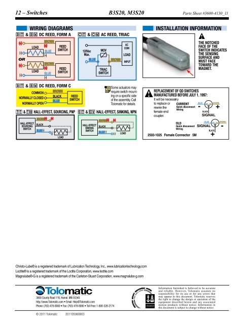
WIRINg DIAgRAMS<br />
INSTALLATION RELEASE<br />
max.<br />
INfORMATION<br />
TIME<br />
120 Vac max.<br />
1.0 msec. max.<br />
OuTPuT RATINg —<br />
R T & R M DC REED, fORM A C T & C M<br />
ON TRIP POINT<br />
—<br />
—<br />
25<br />
AC REED, TRIAC<br />
0.6 msec max.<br />
0.7 msec<br />
Off<br />
max.<br />
OPERATINg TIME<br />
TRIP POINT — —<br />
<<br />
(including bounce) (including bounce)<br />
(+)<br />
BROWN<br />
**POWER RATINg (WATTS) THE NOTCHED 10.0 § 3.0<br />
OPERATINg<br />
LOAD<br />
(+)<br />
AC TEMPERATuRE -40°F [-40°C] to 158°F [70°C] 0°F § §<br />
[-18<br />
REED<br />
VOLTAgE DROP<br />
COM<br />
fACE 2.6 Of V typical THE <strong>at</strong> 100 mA NA<br />
RELEASE TIME 1.0 msec. max. —<br />
BLUE SWITCH<br />
SWITCH INDICATES<br />
(-)<br />
120Vac MOV<br />
RESISTANCE<br />
0.1 Ω Initial (Max.)<br />
ON TRIP POINT — — 150<br />
(-)<br />
Max.<br />
LOAD<br />
THE SENSINg<br />
Off TRIP POINT — CuRRENT CONSuMPTION<br />
OR<br />
SuRfACE — AND —<br />
40<br />
BLUE<br />
BROWN **POWER RATINg INPUT (WATTS) 10.0 § 3.0 § § MuST fACE<br />
(+)<br />
BROWN<br />
fREQuENCY<br />
10.0<br />
—<br />
VOLTAgE DROP 2.6 V typical <strong>at</strong> 100 mA TOWARD THE<br />
(+)<br />
CABLE MIN.<br />
NA<br />
STATIC<br />
—<br />
REED<br />
MAgNET.<br />
LOAD<br />
TRIAC<br />
RESISTANCE 0.1 Ω Initial (Max.) BEND<br />
—<br />
BLUE SWITCH<br />
SWITCH<br />
RADIuS DYNAMIC<br />
(-)<br />
1 Amp <strong>at</strong> 0.5 Amp <strong>at</strong><br />
CuRRENT CONSuMPTION —<br />
20<br />
(-)<br />
86°F [30°C] 140°F [60°C]<br />
CAuTION: DO NOT OVER TIgHTEN SWITCH HARDWARE WHEN<br />
fREQuENCY — 47 - 63 Hz<br />
** WARNINg: Do not exceed power r<strong>at</strong>ing (W<strong>at</strong>t = Voltage X Amperage). P<br />
B T & B M DC REED, fORM C<br />
CABLE MIN. STATIC<br />
0.630" [16mm]<br />
Some actu<strong>at</strong>ors BEND may<br />
*QD = Quick Disconnect; Male coupler is loc<strong>at</strong>ed 6" [152mm} from senso<br />
COMMON<br />
BROWN<br />
require RADIuS switch mounting<br />
on a specific side Manufactured REPLACEMENT be<strong>for</strong>e July Of 1,<br />
DYNAMIC Replacement of QD Switches Female Not Recommended coupler to fl ying lead (part #2503-1025<br />
THE NOTCHED<br />
NORMALLY CLOSED<br />
BLACK REED<br />
gROOVE QD 1997: SWITCHES IN THE MANufACTuRED BEfORE J<br />
BLUE SWITCH<br />
of <strong>the</strong><br />
CAuTION:<br />
assembly.<br />
DO<br />
Call<br />
NOT OVER TIgHTEN It will SWITCH be necessary HARDWARE WHEN INSTALLINg!<br />
ACTuATOR<br />
NORMALLY OPEN<br />
<strong>Tol</strong>om<strong>at</strong>ic ** WARNINg: <strong>for</strong> details. Do not exceed power to r<strong>at</strong>ing replace (W<strong>at</strong>t or = Voltage CuRRENT X Amperage). Permanent BLUE damage to BROWN sensor will occur.<br />
INDICATES THE OLD<br />
*QD = Quick Disconnect; Male coupler rewire is loc<strong>at</strong>ed <strong>the</strong> 6" [152mm}<br />
Quick<br />
from<br />
disconnect<br />
sensor, -<br />
Wiring gROOVE TO +<br />
Quick disconne<br />
Wiring<br />
T T & T M HALL-EffECT, SOuRCINg, PNP K T & K M HALL-EffECT, SINKINg, NPN<br />
Female coupler female to end fl ying lead (part #2503-1025) distance<br />
INSTALL BLACK is 197" [5m]<br />
THE<br />
also see Cable Shielding specifi c<strong>at</strong>io<br />
REPLACEMENT Of QD SWITCHES coupler. MANufACTuRED BEfORE JuLY 1, SWITCH. 1997: SIGNAL It will CONTACT be necessary to replace or rewire <strong>the</strong><br />
BROWN(+)<br />
(+)<br />
BROWN(+)<br />
(+)<br />
†<br />
Shielded from <strong>the</strong> female TOLOMATIC quick disconnect IF coupler to <strong>the</strong> fl ying leads. Shie<br />
HALL-EFFECT<br />
CuRRENT<br />
BLUE<br />
BROWN<br />
BLUE<br />
BROWN<br />
§ SWITCHES ARE<br />
SOURCING<br />
BLACK<br />
OLD<br />
HALL-EFFECT<br />
Maximum current 500mA (not to exceed 10VA) Refer to Temper<strong>at</strong>ure Reed Switc vs. C<br />
BLACK Quick disconnect +<br />
REQUIRED ON<br />
SWITCH<br />
SINKING<br />
-<br />
Quick disconnect SIGNAL<br />
Wiring<br />
§§<br />
-<br />
200,000,00<br />
BLUE (-)<br />
Wiring Maximum current 250mA (not to exceed 3VA) Refer to Temper<strong>at</strong>ure vs. C<br />
SWITCH<br />
BLACK<br />
BLUE (-)<br />
ANOTHER BLACKSIDE OF<br />
rent, duty cy<br />
(-)<br />
(-) LOAD SIGNAL 2503-1025 Female Connector 5M ACTUATOR. +<br />
LOAD<br />
†<br />
Shielded from <strong>the</strong> female quick disconnect coupler to <strong>the</strong> fl ying leads. Shield should be termin<strong>at</strong>ed <strong>at</strong> fl ying lead end.<br />
§<br />
Maximum current 500mA (not to exceed 10VA) Refer to Temper<strong>at</strong>ure vs. Current graph and Voltage Der<strong>at</strong>ing graph<br />
§§<br />
Maximum current 250mA (not to exceed 3VA) Refer to Temper<strong>at</strong>ure vs. Current graph and Voltage Der<strong>at</strong>ing graph<br />
LOAD CURR<br />
LOAD CUR<br />
VOLTAGE A.C<br />
REE D<br />
FORM<br />
C<br />
REED FORM A<br />
Christo-Lube® is a registered trademark of Lubric<strong>at</strong>ion Technology, Inc., www.lubric<strong>at</strong>iontechnology.com<br />
Loctite® is a registered trademark of <strong>the</strong> Loctite Corpor<strong>at</strong>ion, www.loctite.com<br />
Magnalube®-G is a registered trademark of <strong>the</strong> Carleton-Stuart Corpor<strong>at</strong>ion, www.magnalube-g.com<br />
3800 County Road 116, Hamel, MN 55340<br />
http://www.<strong>Tol</strong>om<strong>at</strong>ic.com • Email: Help@<strong>Tol</strong>om<strong>at</strong>ic.com<br />
Phone: (763) 478-8000 • Fax: (763) 478-8080 • <strong>Tol</strong>l Free: 1-800-328-2174<br />
© 2011 <strong>Tol</strong>om<strong>at</strong>ic 201105060803<br />
8<br />
In<strong>for</strong>m<strong>at</strong>ion furnished is believed to be accur<strong>at</strong>e<br />
and reliable. However, <strong>Tol</strong>om<strong>at</strong>ic assumes no<br />
responsibility <strong>for</strong> its use or <strong>for</strong> any errors th<strong>at</strong><br />
may appear in this document. <strong>Tol</strong>om<strong>at</strong>ic reserves<br />
<strong>the</strong> right to change <strong>the</strong> design or oper<strong>at</strong>ion of <strong>the</strong><br />
equipment described herein and any associ<strong>at</strong>ed<br />
motion products without notice. In<strong>for</strong>m<strong>at</strong>ion in<br />
this document is subject to change without notice.


