Parts Sheet - You are now at the Down-Load Site for Tol-O - Tolomatic
Parts Sheet - You are now at the Down-Load Site for Tol-O - Tolomatic
Parts Sheet - You are now at the Down-Load Site for Tol-O - Tolomatic
You also want an ePaper? Increase the reach of your titles
YUMPU automatically turns print PDFs into web optimized ePapers that Google loves.
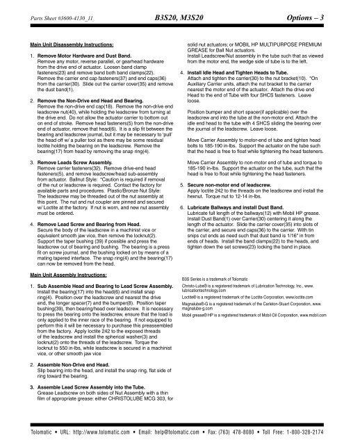
<strong>Parts</strong> <strong>Sheet</strong> #3600-4130_11_B3S20ps B3S20, M3S20 Options – 3<br />
Main Unit Disassembly Instructions:<br />
1. Remove Motor Hardw<strong>are</strong> and Dust Band.<br />
Remove any motor, reverse parallel, or gearhead hardw<strong>are</strong><br />
from <strong>the</strong> drive end of actu<strong>at</strong>or. Loosen band clamp<br />
fasteners(23) and remove band both band clamps(22).<br />
Remove <strong>the</strong> carrier end cap fasteners(37) and end caps(36)<br />
from <strong>the</strong> carrier(30). Slide out <strong>the</strong> carrier cover(35) and remove<br />
<strong>the</strong> dust band(1).<br />
2. Remove <strong>the</strong> Non-Drive end Head and Bearing.<br />
Remove <strong>the</strong> non-drive end cap(18). Remove <strong>the</strong> non-drive end<br />
leadscrew nut(40), while holding <strong>the</strong> leadscrew from turning <strong>at</strong><br />
<strong>the</strong> drive end. Do not allow <strong>the</strong> actu<strong>at</strong>or carrier to bottom out<br />
on end of stroke. Remove head fasteners(5) from <strong>the</strong> non-drive<br />
end of actu<strong>at</strong>or, remove th<strong>at</strong> head(6). It is a slip fit between <strong>the</strong><br />
bearing and leadscrew journal, but it may be necessary to ‘pull’<br />
<strong>the</strong> head off w/ a puller tool as <strong>the</strong>re may be some residual<br />
loctite holding <strong>the</strong> bearing on <strong>the</strong> leadscrew. Remove <strong>the</strong><br />
bearing(17) from head by removing <strong>the</strong> snap ring(4).<br />
3. Remove Leads Screw Assembly.<br />
Remove carrier fasteners(32). Remove drive-end head<br />
fasteners(5), and remove leadscrew/head sub-assembly<br />
from actu<strong>at</strong>or. Ballnut Style: *Caution is required if removal<br />
of <strong>the</strong> nut or leadscrew is required. Contact <strong>the</strong> factory <strong>for</strong><br />
available parts and procedures. Plastic/Bronze Nut Style:<br />
The leadscrew may be threaded out of <strong>the</strong> nut assembly <strong>at</strong><br />
this point. The nut and nut coupler <strong>are</strong> pinned and secured<br />
w/ Loctite <strong>at</strong> <strong>the</strong> factory. If nut is worn, and new nut assembly<br />
must be ordered.<br />
4. Remove Lead Screw and Bearing from Head.<br />
Secure <strong>the</strong> body of <strong>the</strong> leadscrew in a machinist vice or<br />
equivalent smooth jaw vice, <strong>the</strong>n remove <strong>the</strong> locknut(2).<br />
Support <strong>the</strong> taper bushing (39) if possible and press <strong>the</strong><br />
leadscrew out of bearing and bushing. The bearing is a press<br />
fit on screw journal, and <strong>the</strong> bushing locked on by means of a<br />
m<strong>at</strong>ing tapered interface. The snap ring(4) and <strong>the</strong> bearing(17)<br />
can <strong>now</strong> be removed from <strong>the</strong> head.<br />
Main Unit Assembly Instructions:<br />
1. Sub Assemble Head and Bearing to Lead Screw Assembly.<br />
Install <strong>the</strong> bearing(17) into <strong>the</strong> head(6) and install snap<br />
ring(4). Position over <strong>the</strong> leadscrew and ne<strong>are</strong>st <strong>the</strong> drive<br />
end, <strong>the</strong> longer spacer(7) and <strong>the</strong> bumper(8). Position taper<br />
bushing(39), <strong>the</strong>n bearing/head over leadscrew. It is necessary<br />
to press <strong>the</strong> bearing onto <strong>the</strong> leadscrew, ensure th<strong>at</strong> <strong>the</strong> load is<br />
only applied to <strong>the</strong> inner race of <strong>the</strong> bearing. If not equipped to<br />
per<strong>for</strong>m this it will be necessary to purchase this preassembled<br />
from <strong>the</strong> factory. Apply loctite 242 to <strong>the</strong> exposed threads<br />
of <strong>the</strong> leadscrew and install <strong>the</strong> spherical washer(3) and<br />
locknut(2) onto <strong>the</strong> threads of <strong>the</strong> leadscrew. Torque <strong>the</strong><br />
locknut to 550 in-lbs, while leadscrew is secured in a machinist<br />
vice, or o<strong>the</strong>r smooth jaw vice<br />
solid nut actu<strong>at</strong>ors; or MOBIL HP MULTIPURPOSE PREMIUM<br />
GREASE <strong>for</strong> Ball Nut actu<strong>at</strong>ors.<br />
Install Leadscrew/Nut assembly in <strong>the</strong> tube such th<strong>at</strong> as viewed<br />
from <strong>the</strong> motor end, <strong>the</strong> wedge side of tube is to <strong>the</strong> left.<br />
4. Install Idle Head and Tighten Heads to Tube.<br />
Attach and tighten <strong>the</strong> carrier(30) to <strong>the</strong> nut bracket(10). *On<br />
Auxiliary Carrier units, <strong>at</strong>tach <strong>the</strong> nut bracket to <strong>the</strong> carrier<br />
ne<strong>are</strong>st <strong>the</strong> motor end of <strong>the</strong> actu<strong>at</strong>or. Attach <strong>the</strong> drive end<br />
Head to <strong>the</strong> end of Tube with four SHCS fasteners. Leave<br />
loose.<br />
Position bumper and short spacer(if applicable) over <strong>the</strong><br />
leadscrew and into <strong>the</strong> tube <strong>at</strong> <strong>the</strong> non-motor end. Attach <strong>the</strong><br />
idle end head to <strong>the</strong> tube with 4 SHCS sliding <strong>the</strong> bearing over<br />
<strong>the</strong> journal of <strong>the</strong> leadscrew. Leave loose.<br />
Move Carrier Assembly to motor-end of tube and tighten head<br />
bolts to 185-190 in-lbs. Support <strong>the</strong> actu<strong>at</strong>or on <strong>the</strong> tube such<br />
th<strong>at</strong> <strong>the</strong> head is free to flo<strong>at</strong> while tightening <strong>the</strong> head fasteners.<br />
Move Carrier Assembly to non-motor end of tube and torque to<br />
185-190 in-lbs. Support <strong>the</strong> actu<strong>at</strong>or on <strong>the</strong> tube, such th<strong>at</strong> <strong>the</strong><br />
head is free to flo<strong>at</strong> while tightening <strong>the</strong> head fasteners.<br />
5. Secure non-motor end of leadscrew.<br />
Apply loctite 242 to <strong>the</strong> threads on <strong>the</strong> leadscrew and install <strong>the</strong><br />
hexnut. Torque nut to 12-14 in-lbs.<br />
6. Lubric<strong>at</strong>e Ballways and install Dust Band.<br />
Lubric<strong>at</strong>e full length of <strong>the</strong> ballways(12) with Mobil HP grease.<br />
Install Dust Band(1) over Carrier(30) centering it along <strong>the</strong><br />
length of <strong>the</strong> actu<strong>at</strong>or. Slide <strong>the</strong> carrier cover(35) into slots of<br />
<strong>the</strong> carrier, and secure end caps(36) to <strong>the</strong> carrier. With tin<br />
snips cut ends as need such th<strong>at</strong> dust band is 1/16" in from<br />
ends of heads. Install <strong>the</strong> band clamps(22) to <strong>the</strong> heads, and<br />
tighten down <strong>the</strong> set screws(23) locking <strong>the</strong> band in place.<br />
B3S Series is a trademark of <strong>Tol</strong>om<strong>at</strong>ic<br />
Christo-Lube® is a registered trademark of Lubric<strong>at</strong>ion Technology, Inc., www.<br />
lubric<strong>at</strong>iontechnology.com<br />
Loctite® is a registered trademark of <strong>the</strong> Loctite Corpor<strong>at</strong>ion, www.loctite.com<br />
Magnalube®-G is a registered trademark of <strong>the</strong> Carleton-Stuart Corpor<strong>at</strong>ion, www.<br />
magnalube-g.com<br />
Mobil grease® HP is a registered trademark of Mobil Oil Corpor<strong>at</strong>ion, www.mobil.com<br />
2. Assemble Non-Drive end Head.<br />
Slip bearing into <strong>the</strong> head, and install <strong>the</strong> snap ring, fl<strong>at</strong> side of<br />
ring toward <strong>the</strong> bearing.<br />
3. Assemble Lead Screw Assembly into <strong>the</strong> Tube.<br />
Grease Leadscrew on both sides of Nut Assembly with a thin<br />
film of appropri<strong>at</strong>e grease: ei<strong>the</strong>r CHRISTOLUBE MCG 303, <strong>for</strong><br />
<strong>Tol</strong>om<strong>at</strong>ic • URL: http://www.tolom<strong>at</strong>ic.com • Email: help@tolom<strong>at</strong>ic.com • Fax: (763) 478-8080 • <strong>Tol</strong>l Free: 1-800-328-2174


